EP1636454B1 - Electromechanical lock cylinder - Google Patents
Electromechanical lock cylinder Download PDFInfo
- Publication number
- EP1636454B1 EP1636454B1 EP04737108A EP04737108A EP1636454B1 EP 1636454 B1 EP1636454 B1 EP 1636454B1 EP 04737108 A EP04737108 A EP 04737108A EP 04737108 A EP04737108 A EP 04737108A EP 1636454 B1 EP1636454 B1 EP 1636454B1
- Authority
- EP
- European Patent Office
- Prior art keywords
- lock
- knob
- coupling element
- driver
- lock cylinder
- Prior art date
- Legal status (The legal status is an assumption and is not a legal conclusion. Google has not performed a legal analysis and makes no representation as to the accuracy of the status listed.)
- Not-in-force
Links
Images


Classifications
-
- E—FIXED CONSTRUCTIONS
- E05—LOCKS; KEYS; WINDOW OR DOOR FITTINGS; SAFES
- E05B—LOCKS; ACCESSORIES THEREFOR; HANDCUFFS
- E05B47/00—Operating or controlling locks or other fastening devices by electric or magnetic means
- E05B47/06—Controlling mechanically-operated bolts by electro-magnetically-operated detents
- E05B47/0676—Controlling mechanically-operated bolts by electro-magnetically-operated detents by disconnecting the handle
- E05B47/0684—Controlling mechanically-operated bolts by electro-magnetically-operated detents by disconnecting the handle radially
- E05B47/0692—Controlling mechanically-operated bolts by electro-magnetically-operated detents by disconnecting the handle radially with a rectilinearly moveable coupling element
-
- E—FIXED CONSTRUCTIONS
- E05—LOCKS; KEYS; WINDOW OR DOOR FITTINGS; SAFES
- E05B—LOCKS; ACCESSORIES THEREFOR; HANDCUFFS
- E05B47/00—Operating or controlling locks or other fastening devices by electric or magnetic means
- E05B47/06—Controlling mechanically-operated bolts by electro-magnetically-operated detents
- E05B47/0611—Cylinder locks with electromagnetic control
- E05B47/0638—Cylinder locks with electromagnetic control by disconnecting the rotor
- E05B47/0646—Cylinder locks with electromagnetic control by disconnecting the rotor radially
- E05B47/0649—Cylinder locks with electromagnetic control by disconnecting the rotor radially with a rectilinearly moveable coupling element
-
- E—FIXED CONSTRUCTIONS
- E05—LOCKS; KEYS; WINDOW OR DOOR FITTINGS; SAFES
- E05B—LOCKS; ACCESSORIES THEREFOR; HANDCUFFS
- E05B47/00—Operating or controlling locks or other fastening devices by electric or magnetic means
- E05B47/0001—Operating or controlling locks or other fastening devices by electric or magnetic means with electric actuators; Constructional features thereof
- E05B2047/0014—Constructional features of actuators or power transmissions therefor
- E05B2047/0018—Details of actuator transmissions
- E05B2047/0024—Cams
- E05B2047/0025—Cams in the form of grooves
-
- E—FIXED CONSTRUCTIONS
- E05—LOCKS; KEYS; WINDOW OR DOOR FITTINGS; SAFES
- E05B—LOCKS; ACCESSORIES THEREFOR; HANDCUFFS
- E05B47/00—Operating or controlling locks or other fastening devices by electric or magnetic means
- E05B2047/0048—Circuits, feeding, monitoring
- E05B2047/0067—Monitoring
-
- E—FIXED CONSTRUCTIONS
- E05—LOCKS; KEYS; WINDOW OR DOOR FITTINGS; SAFES
- E05B—LOCKS; ACCESSORIES THEREFOR; HANDCUFFS
- E05B47/00—Operating or controlling locks or other fastening devices by electric or magnetic means
- E05B47/0001—Operating or controlling locks or other fastening devices by electric or magnetic means with electric actuators; Constructional features thereof
- E05B47/0012—Operating or controlling locks or other fastening devices by electric or magnetic means with electric actuators; Constructional features thereof with rotary electromotors
-
- Y—GENERAL TAGGING OF NEW TECHNOLOGICAL DEVELOPMENTS; GENERAL TAGGING OF CROSS-SECTIONAL TECHNOLOGIES SPANNING OVER SEVERAL SECTIONS OF THE IPC; TECHNICAL SUBJECTS COVERED BY FORMER USPC CROSS-REFERENCE ART COLLECTIONS [XRACs] AND DIGESTS
- Y10—TECHNICAL SUBJECTS COVERED BY FORMER USPC
- Y10T—TECHNICAL SUBJECTS COVERED BY FORMER US CLASSIFICATION
- Y10T70/00—Locks
- Y10T70/70—Operating mechanism
- Y10T70/7051—Using a powered device [e.g., motor]
- Y10T70/7062—Electrical type [e.g., solenoid]
- Y10T70/7102—And details of blocking system [e.g., linkage, latch, pawl, spring]
-
- Y—GENERAL TAGGING OF NEW TECHNOLOGICAL DEVELOPMENTS; GENERAL TAGGING OF CROSS-SECTIONAL TECHNOLOGIES SPANNING OVER SEVERAL SECTIONS OF THE IPC; TECHNICAL SUBJECTS COVERED BY FORMER USPC CROSS-REFERENCE ART COLLECTIONS [XRACs] AND DIGESTS
- Y10—TECHNICAL SUBJECTS COVERED BY FORMER USPC
- Y10T—TECHNICAL SUBJECTS COVERED BY FORMER US CLASSIFICATION
- Y10T70/00—Locks
- Y10T70/70—Operating mechanism
- Y10T70/7051—Using a powered device [e.g., motor]
- Y10T70/7062—Electrical type [e.g., solenoid]
- Y10T70/713—Dogging manual operator
Definitions
- the invention relates to an electromechanical lock cylinder, which can cooperate with an evaluation for detecting an access authorization and having a housing which comprises two opposing cylindrical receptacles in which either a respective lock core, which is actuated by a key, or in each case a knob shaft, the rotatably connected to a knob, are rotatably supported, wherein the lock cores or the knob shafts interact with a locking lug, which can in particular actuate a latch or a latch of a door lock, and with matching key or access authorization an electromechanically driven locking or coupling element of the Resting position is moved into an operative position and generates a rotationally fixed connection between the key or knob and the locking lug, while the locking lug od in the rest position of the locking or coupling element relative to both locking cores it is freely rotatable to both Knaufwellen.
- the lock cylinder may comprise a housing comprising two opposed cylindrical receptacles in which on one side of the housing a lock core which is actuated by a key, and on the opposite side a knob shaft which is rotatably connected to a knob, are rotatably mounted. It is also possible that the lock cylinder has a housing which comprises a cylindrical receptacle in which either a lock core, which can be actuated by a key, or a knob shaft, which is rotatably connected to a knob, is rotatably mounted, wherein the lock core or the knob shaft cooperate with a locking lug.
- the invention thus relates firstly to two-sided lock cylinder with two opposing receptacles in which either a lock core on either side or both sides a knob shaft or in which on one side a knob shaft and on the other side a lock core are stored.
- the invention relates to one-sided lock cylinder, so-called half cylinder, with only one receptacle in which either a lock core or a knob shaft is rotatably mounted.
- electromechanical lock cylinders that can be actuated with a key, in addition to a frequently still mechanically matching key also requires a matching electronically readable code to produce an operative connection between the key and the locking lug.
- the electronically readable code can be supplied wirelessly via transponder or via electrical contacts to a transmitter.
- the evaluation electronics controls the electromechanical locking or coupling element so that the locking lug can be rotated.
- Such lock cylinders are known in different embodiments.
- Such a lock cylinder is, for example, by the DE 199 30 054 A1 disclosed.
- the arrangement is such that on one side of the cylinder housing a rotary knob is present, the rotationally fixed on the Knock shaft is connected to the locking lug. An actuation is therefore always possible from this page.
- On the opposite side of the lock cylinder can be actuated by a key, which additionally carries an electrical coding.
- the electronic evaluation unit is located in the rotary knob, and the decoding signal must be passed from arranged in the cylinder housing antenna via at least one slip ring contact to the electronic evaluation.
- slip ring contacts are relatively expensive to manufacture in the required reliability.
- a lock cylinder is known in which the locking lug is freely rotatable in the rest position relative to the lock core.
- the non-rotatable connection between the lock core and locking lug is effected by an axially displaceable sleeve.
- the DE 196 03 320 A1 describes a lock cylinder in which the rotationally fixed connection between the closing lug and the lock core is produced by a cam extending by means of centrifugal force.
- the WO 02/088492 A2 discloses a locking pin for a locking core, which is driven via an eccentric and arranged in the lock cylinder housing.
- a problem with such lock cylinders when the lock cylinder from both sides should be closed only with appropriate access authorization by means of a knob and / or a key.
- the closing lug is then fixedly connected to the lock core and / or the knob shaft, which is or is locked via a locking element mounted in the cylinder housing. It can be applied in particular by a rotary knob relatively high forces that are sufficient to destroy the blocking element. Forcible opening is therefore possible.
- the invention has for its object to make a lock cylinder different so that a reliable operation in a compact design is possible.
- the locking or coupling element is arranged on or in the lock core or on or in the knob shaft and rotates with this or this and includes an eccentric, a driver between the rest position and the active position - And moved, in which it engages in a recess of the locking lug or a rotary sleeve, on which the locking lug is arranged.
- This has the advantage that there is no connection to the locking lug without access authorization. Without access authorization, the locking lug therefore can not be operated with an externally accessible element even in the case of violence. Also, a signal transmission via slip ring contacts is no longer required, so that the reliability and reliability can be increased.
- the locking or coupling element is designed as a driver, which engages in a corresponding recess in the rotary sleeve or the locking lug. It is achieved a very compact structure.
- an electric motor drive with an eccentric drive for the driver reliable operation is achieved in a very compact design.
- electric motors are easily controllable and have a relatively low power consumption.
- the electric motor in one or the other end position are switched off so that no energy is consumed after the stroke movement effected both in the rest position and in the operative position. The lifetime of the generally off-grid power supply can thus be increased.
- the closing nose is therefore freely rotatable in the rest position of the blocking or coupling element relative to both locking cores.
- a knob shaft is present on both sides of the housing, the locking lug in the rest position of the locking or coupling element is freely rotatable relative to both knob shafts.
- the locking lug in the rest position of the locking or coupling element is freely rotatable relative to the lock core and the knob shaft.
- the locking lug is freely rotatable in the rest position of the coupling element either to the lock core or to the knob shaft.
- a continuous closing core or a continuous knob shaft is present, which extends from one side of the housing to the opposite side and can be actuated from both sides by a key or a knob.
- This embodiment is advantageous, for example, if there is a rotary knob with the evaluation electronics on both sides.
- a Lock cylinder with knob shaft and lock core lock core and knob shaft can be rotatably connected together or integrally formed.
- the blocking or coupling element comprises an electromagnetic drive.
- the blocking or coupling element comprises an electric motor drive. Both electromagnets and electric motors are available with small installation dimensions, so that they can be easily integrated into the knob shaft or the lock core. Nevertheless, there is still the possibility to equip the lock core, for example, with conventional pin tumblers.
- the rest position and / or the active position of the driver are by a predeterminable angle of rotation beyond the associated dead centers of the eccentric.
- the respective angle of rotation can be 10 ° to 30 ° above the respective dead center. It is advantageous if the eccentric abuts against a stop after reaching the angle of rotation, which limits and prevents further rotation. This has the advantage that the end positions are achieved with certainty and reproducible. In particular, over-rotation beyond the end position is reliably avoided. Also, the eccentric better in these end positions, for example, by spring or locking elements whose holding force can be overcome by the engine power held.
- the eccentric drive can have an eccentrically arranged about the motor axis pin, which in a transverse to the lifting movement of the driver and perpendicular to the motor axis extending groove thereof engages the position and length is dimensioned so that a rotational movement from the rest position to the operative position only in one direction and the rotational movement of the active position in the rest position of the driver only in the opposite direction of rotation is possible.
- the motor then only needs to be controlled accordingly, namely counterclockwise to reach the rest position and clockwise to reach the active position, or vice versa. This is possible with simple technical means.
- the length and position of the groove is chosen so that further rotation of the eccentric is possible from the rest position to the operative position of the driver beyond the dead center by the rotation angle, and vice versa.
- the length of the groove in this extension which corresponds to a further rotation in the same direction of rotation is shortened, so that a further rotation beyond 90 ° and preferably beyond 45 ° is not possible to prevent spinning. This can be effected by simple means, the desired and targeted lifting movement of the driver by an eccentric.
- the locking lug is freely rotatably mounted to the knob shaft or the lock core and thus freely rotatable relative to the driver on the cylinder housing, the free end of the driver in the rest position and the recess of the locking lug are necessarily not always aligned. A movement of a rigid driver from the rest position into the active position is not possible with twisted recess.
- the driver comprises a plunger whose free end is guided in a sleeve whose free end is immersed in the operative position in the recess of the locking lug or the rotary sleeve and in the interior of which a compression spring is arranged, which cooperates with the free end of the plunger ,
- a compression spring is arranged, which cooperates with the free end of the plunger
- the sleeve has a stop on its side opposite the free end, against which a thickened end of the plunger strikes. This has the advantage that the sleeve is forcibly pulled along in a movement of the plunger in the Ruhlage. Clamping of the sleeve in the recess is avoided.
- the depth of the recess of the locking lug or the rotary sleeve is dimensioned so that when engaging driver, the compression spring in the sleeve is still under tension. This will achieve that the eccentric is held in the operative position under bias. Since the active position in the direction of rotation of the eccentric is behind the dead center, a reverse rotation of the eccentric is prevented when engaged driver.
- the driver is held in the rest position by a spring force. Since here also the rest position in the direction of rotation of the eccentric behind the associated dead center, a reverse rotation of the eccentric is prevented in a disengaged driver.
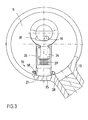
- the knob shaft 11 shown in the drawing is rotatably mounted in a hollow cylindrical receptacle 12 of a lock cylinder, not shown. Alternatively it can be stored in the wood cylindrical receptacle and a lock core, which is actuated by means of a key, in particular via mechanical tumblers.
- the knob shaft shown would be relevant here correspond to pictorial representation of a lock core, so that in the following reference is made only to the knob shaft.
- the knob shaft 11 is rotatably connected in a manner not shown with a rotary knob. It is also provided with an electronic evaluation means that can interrogate and evaluate in a known manner an electronic access code of a key or other key element.
- the lock cylinder also has a locking lug 13, which cooperates with a locking bolt of a lock, not shown.
- an electromechanically operating blocking or coupling element 14 which is described below, is activated, by means of which a rotationally fixed connection between the closing nose and the knob shaft 11 is effected. Then, the lock cylinder can be operated by the knob shaft is rotated with the knob or the lock core by means of a key. From the basic structure, the dimensions and in particular with respect to the electronic detection and evaluation of the access code corresponds to the lock cylinder so far a conventional electromechanical lock cylinder and therefore requires no further explanation.
- the arrangement is such that the locking lug is freely rotatably supported by a rotary sleeve 35 on the knob shaft in the housing.
- the electromechanically operating blocking or coupling element 14 is arranged in the knob shaft 11 and comprises an eccentric with a rotor 15, on which an axially extending pin 16 is arranged eccentrically to the eccentric axis 17.
- the pin 16 acts via a groove 18 with a driver 19 together, which moves up and down due to the rotational movement of the rotor.
- the driver 19 is guided in a guide channel 20 of the knob shaft 11 linearly and in the radial direction to the knob shaft.
- the groove 18 extends substantially transversely to the stroke direction of the driver 19.
- the position and the length of the groove are chosen so that, starting from the in Fig. 1 shown rest position, only by a rotation of the rotor 15 in the direction of rotation 21 of the driver 19 in the in Fig. 2 shown active position can be brought. From the operative position of the driver can be brought back into the rest position only by a rotation in the direction 22.
- the length and the position of the groove are chosen so that the eccentric can be rotated in its end positions in each case beyond the dead center of the respective position by a rotation angle.
- This angle can be for example 10 ° to 30 °.
- the range of the groove shown on the right in the drawing is such that further rotation of the rotor in the direction of rotation 22 by more than the predetermined rotation angle above the top dead center (rest position) is not possible because the pin 16 previously at the frontal boundary of Groove strikes. The same applies to the movement in the direction of rotation 21 beyond the bottom dead center (active position) addition.
- the driver 19 has a plunger 24, one end of which carries the groove 18 and is mounted on the pin 16 of the eccentric.
- the free end 25 of the plunger is guided in a sleeve 26.
- the opposite free end 27 of the sleeve emerges in the Fig. 2 shown active position in a recess 28 of the locking lug. Then there is a non-rotatable connection between the locking lug and the knob shaft and thus between the locking lug and the knob, and the lock can be actuated.
- a compression spring 29 is arranged, which cooperates with the free end of the plunger. It is at the opposite end of the free end of the sleeve 26, a stop 30 is provided, against which the thickened end 25 of the plunger 24 abuts.
- the sleeve is held securely on the plunger.
- the free end 27 engages only in the course of a rotary movement of the knob shaft, as soon as the free end 27 passes over the recess. This safe operation is achieved even with twisted locking lug, which in the rest position of the driver relative to the Knauf shaft and also freely rotatable to the housing of the lock cylinder.
- the free end 27 of the sleeve is formed as an expanding projection 32 with a narrower neck portion 34 and a rounded end edge. In order for a secure engagement of the projection when passing over the recess 28 is achieved when the spring 29 tensioned.
- the recess 28 of the locking lug 13 is closed in the insertion direction of the driver or a stop 33, wherein the depth of the recess is dimensioned so that when immersed projection 32, the compression spring 29 is still under tension and the free end 25 of Tappet not yet abuts the stop 30. This ensures that the eccentric pin 16 is held in tension beyond the associated dead center via the tappet and the groove in the end position of the eccentric corresponding to the active position. The eccentric can then no longer turn back by itself, for example, by gravity, even if the power supply of the drive motor is interrupted.
- detection means 36 are present, which detect the position or the position of the coupling element.
- the detection means may comprise at least one Hall sensor 37 and / or at least and / or at least one capacitive or inductive sensor 38 or a switch 39 which cooperates with a movable element of the coupling element.
- a Hall sensor 37 is an example of a Hall sensor 37 and in Fig. 3
- a capacitive sensor 38 in the form of a capacitor arrangement of half-rings which are influenced on the basis of the position of the driver, are shown.
- the driver is preferably made of metal, so that its position in front of the Hall sensor or between the capacitor rings can be well detected.
- Fig. 1 shows a limit switch 39, which cooperates with the eccentric of the motor.
- the limit switch can be used as Tast switch be formed, which simultaneously applies the spring force to hold the driver in the rest position behind the top dead center of the eccentric.
- a signal corresponding to the position of the coupling element and in particular of the driver can be generated by the sensors or the switch, a signal corresponding to the position of the coupling element and in particular of the driver.
- the coupling element is driven by the transmitter to move to the rest position.
- a signal is present when the coupling element is in the rest position.
- the control of the coupling element and / or the interrogation of the signal can be performed in cycles or after a predetermined period of time.
Abstract
Description
Die Erfindung betrifft einen elektromechanischen Schließzylinder, der mit einer Auswerteelektronik zum Erkennen einer Zugangsberechtigung zusammenwirken kann und ein Gehäuse aufweist, das zwei sich gegenüberliegende zylindrische Aufnahmen umfasst, in denen entweder jeweils ein Schließkern, der durch einen Schlüssel betätigbar ist, oder jeweils eine Knaufwelle, die drehfest mit einem Knauf verbunden ist, drehbar gelagert sind, wobei die Schließkerne oder die Knaufwellen mit einer Schließnase zusammenwirken, die insbesondere einen Riegel oder eine Schließfalle eines Türschlosses betätigen kann, und bei passendem Schlüssel oder erfolgter Zugangsberechtigung ein elektromechanisch angetriebenes Sperr- oder Kupplungselement aus der Ruhestellung in eine Wirkstellung bewegt wird und eine drehfeste Verbindung zwischen Schlüssel oder Knauf und der Schließnase erzeugt, während die Schließnase in der Ruhestellung des Sperr- oder Kupplungselements relativ zu beiden Schließkernen oder zu beiden Knaufwellen frei drehbar ist.The invention relates to an electromechanical lock cylinder, which can cooperate with an evaluation for detecting an access authorization and having a housing which comprises two opposing cylindrical receptacles in which either a respective lock core, which is actuated by a key, or in each case a knob shaft, the rotatably connected to a knob, are rotatably supported, wherein the lock cores or the knob shafts interact with a locking lug, which can in particular actuate a latch or a latch of a door lock, and with matching key or access authorization an electromechanically driven locking or coupling element of the Resting position is moved into an operative position and generates a rotationally fixed connection between the key or knob and the locking lug, while the locking lug od in the rest position of the locking or coupling element relative to both locking cores it is freely rotatable to both Knaufwellen.
Alternativ kann der Schließzylinder ein Gehäuse aufweisen, das zwei sich gegenüberliegende zylindrische Aufnahmen umfasst, in denen auf der einen Seite des Gehäuses ein Schließkern, der durch einen Schlüssel betätigbar ist, und auf der gegenüberliegenden Seite eine Knaufwelle, die drehfest mit einem Knauf verbunden ist, drehbar gelagert sind. Auch ist es möglich, dass der Schließzylinder ein Gehäuse aufweist, das eine zylindrische Aufnahme umfasst, in der entweder ein Schließkern, der durch einen Schlüssel betätigbar ist, oder eine Knaufwelle, die drehfest mit einem Knauf verbunden ist, drehbar gelagert ist, wobei der Schließkern oder die Knaufwelle mit einer Schließnase zusammenwirken.Alternatively, the lock cylinder may comprise a housing comprising two opposed cylindrical receptacles in which on one side of the housing a lock core which is actuated by a key, and on the opposite side a knob shaft which is rotatably connected to a knob, are rotatably mounted. It is also possible that the lock cylinder has a housing which comprises a cylindrical receptacle in which either a lock core, which can be actuated by a key, or a knob shaft, which is rotatably connected to a knob, is rotatably mounted, wherein the lock core or the knob shaft cooperate with a locking lug.
Die Erfindung bezieht sich somit zum einen auf beidseitige Schließzylinder mit zwei sich gegenüberliegenden Aufnahmen, in denen entweder beidseitig jeweils ein Schließkern oder beidseitig jeweils eine Knaufwelle oder in denen auf der einen Seite eine Knaufwelle und auf der anderen Seite ein Schließkern gelagert sind. Zum anderen bezieht sich die Erfindung auf einseitige Schließzylinder, so genannte Halbzylinder, mit nur einer Aufnahme, in der entweder ein Schließkern oder eine Knaufwelle drehbar gelagert ist.The invention thus relates firstly to two-sided lock cylinder with two opposing receptacles in which either a lock core on either side or both sides a knob shaft or in which on one side a knob shaft and on the other side a lock core are stored. On the other hand, the invention relates to one-sided lock cylinder, so-called half cylinder, with only one receptacle in which either a lock core or a knob shaft is rotatably mounted.
Bei elektromechanischen Schließzylindern, die mit einem Schlüssel betätigbar sind, ist neben einem häufig nach wie vor erforderlichen mechanisch passenden Schlüssel auch noch ein passender elektronisch auslesbarer Code erforderlich, um eine Wirkverbindung zwischen Schlüssel und Schließnase herzustellen. Der elektronisch auslesbarer Code kann drahtlos über Transponder oder über elektrische Kontakte einer Auswerteelektronik zugeführt werden. Die Auswertelektronik steuert das elektromechanische Sperr- oder Kupplungselement so an, dass die Schließnase verdreht werden kann. Solche Schließzylinder sind in unterschiedlichen Ausführungsformen bekannt.In electromechanical lock cylinders that can be actuated with a key, in addition to a frequently still mechanically matching key also requires a matching electronically readable code to produce an operative connection between the key and the locking lug. The electronically readable code can be supplied wirelessly via transponder or via electrical contacts to a transmitter. The evaluation electronics controls the electromechanical locking or coupling element so that the locking lug can be rotated. Such lock cylinders are known in different embodiments.
Ein derartiger Schließzylinder wird beispielsweise durch die
Aus der
Ein Problem besteht bei solchen Schließzylindern dann, wenn der Schließzylinder von beiden Seiten nur bei entsprechender Zugangsberechtigung mittels eines Knaufs und/oder eines Schlüssels schließbar sein soll. Die Schließnase ist dann mit dem Schließkern und/oder der Knaufwelle fest verbunden, der beziehungsweise die über ein im Zylindergehäuse gelagertes Sperrelement gesperrt wird. Es können insbesondere durch einen Drehknauf relativ hohe Kräfte aufgebracht werden, die ausreichen, das Sperrelement zu zerstören. Ein gewaltsames Öffnen ist daher möglich.A problem with such lock cylinders when the lock cylinder from both sides should be closed only with appropriate access authorization by means of a knob and / or a key. The closing lug is then fixedly connected to the lock core and / or the knob shaft, which is or is locked via a locking element mounted in the cylinder housing. It can be applied in particular by a rotary knob relatively high forces that are sufficient to destroy the blocking element. Forcible opening is therefore possible.
Der Erfindung liegt die Aufgabe zugrunde, einen Schließzylinder anders zu gestalten derart, dass ein zuverlässiger Betrieb bei kompakter Bauweise möglich ist.The invention has for its object to make a lock cylinder different so that a reliable operation in a compact design is possible.
Die Aufgabe wird gemäß der Erfindung dadurch gelöst, dass das Sperr- oder Kupplungselement auf oder in dem Schließkern oder auf oder in der Knaufwelle angeordnet ist und sich mit diesem oder dieser mitdreht sowie einen Excenter umfasst, der einen Mitnehmer zwischen der Ruhestellung und der Wirkstellung hin- und herbewegt, in der er in eine Ausnehmung der Schließnase oder einer Drehhülse, auf der die Schließnase angeordnet ist, eingreift. Dies hat den Vorteil, dass zu der Schließnase ohne Zugangsberechtigung überhaupt keine Verbindung besteht. Ohne Zugangsberechtigung ist die Schließnase daher nicht mit einem von außen zugänglichen Element auch bei Gewaltanwendung nicht zu betätigen. Auch ist eine Signalübertragung über Schleifringkontakte nicht mehr erforderlich, so dass die Betriebssicherheit und -zuverlässigkeit erhöht werden kann. Ferner ist das Sperr- oder Kupplungselement als Mitnehmer ausgebildet, der in eine entsprechende Ausnehmung in der Drehhülse oder der Schließnase eingreift. Es wird ein sehr kompakter Aufbau erreicht.The object is achieved according to the invention in that the locking or coupling element is arranged on or in the lock core or on or in the knob shaft and rotates with this or this and includes an eccentric, a driver between the rest position and the active position - And moved, in which it engages in a recess of the locking lug or a rotary sleeve, on which the locking lug is arranged. This has the advantage that there is no connection to the locking lug without access authorization. Without access authorization, the locking lug therefore can not be operated with an externally accessible element even in the case of violence. Also, a signal transmission via slip ring contacts is no longer required, so that the reliability and reliability can be increased. Further, the locking or coupling element is designed as a driver, which engages in a corresponding recess in the rotary sleeve or the locking lug. It is achieved a very compact structure.
Durch den vorteilhaften Einsatz eines elektromotorischen Antriebs mit einem Exzenterantrieb für den Mitnehmer wird ein zuverlässiger Betrieb bei sehr kompakter Bauweise erreicht. Insbesondere sind Elektromotoren leicht steuerbar und weisen einen relativ geringen Stromverbrauch auf. Insbesondere kann der Elektromotor in der einen oder andere Endlage abgeschaltet werden, so dass nach der bewirkten Hubbewegung sowohl in der Ruhestellung als auch in der Wirkstellung keine Energie mehr verbraucht wird. Die Lebenszeit der im Allgemeinen netzunabhängigen Stromversorgung kann somit erhöht werden.The advantageous use of an electric motor drive with an eccentric drive for the driver reliable operation is achieved in a very compact design. In particular, electric motors are easily controllable and have a relatively low power consumption. In particular, the electric motor in one or the other end position are switched off so that no energy is consumed after the stroke movement effected both in the rest position and in the operative position. The lifetime of the generally off-grid power supply can thus be increased.
Sofern auf beiden Seiten des Gehäuses ein Schließkern vorhanden ist, ist die Schließnase demnach in der Ruhestellung des Sperr- oder Kupplungselements relativ zu beiden Schließkernen frei drehbar. Sofern auf beiden Seiten des Gehäuses eine Knaufwelle vorhanden ist, ist die Schließnase in der Ruhestellung des Sperr- oder Kupplungselements relativ zu beiden Knaufwellen frei drehbar. Sofern in der einen Aufnahme ein Schließkern und in der anderen Aufnahme eine Knaufwelle drehbar gelagert sind, ist die Schließnase in der Ruhestellung des Sperr- oder Kupplungselements relativ zu dem Schließkern und der Knaufwelle frei drehbar ist. Bei einem Halbzylinder mit nur einem Schließkern oder nur einer Knaufwelle ist die Schließnase in der Ruhestellung des Kupplungselements entweder zum Schließkern oder zur Knaufwelle frei drehbar.If a closing core is present on both sides of the housing, the closing nose is therefore freely rotatable in the rest position of the blocking or coupling element relative to both locking cores. If a knob shaft is present on both sides of the housing, the locking lug in the rest position of the locking or coupling element is freely rotatable relative to both knob shafts. If in one receptacle a lock core and in the other receptacle a knob shaft are rotatably mounted, the locking lug in the rest position of the locking or coupling element is freely rotatable relative to the lock core and the knob shaft. In a half-cylinder with only one lock core or only one knob shaft, the locking lug is freely rotatable in the rest position of the coupling element either to the lock core or to the knob shaft.
Gemäß einer weitergehenden Ausführungsform der Erfindung ist vorgesehen, dass ein durchgehender Schließkern oder eine durchgehende Knaufwelle vorhanden ist, der beziehungsweise die sich von einer Seite des Gehäuses zur gegenüberliegenden Seite erstreckt und von beiden Seiten durch einen Schlüssel oder einen Knauf betätigbar ist. Diese Ausführungsform ist beispielsweise dann günstig, wenn auf beiden Seiten ein Drehknauf mit der Auswerteelektronik vorhanden ist. Bei einem Schließzylinder mit Knaufwelle und Schließkern können Schließkern und Knaufwelle drehfest miteinander verbunden oder einstückig ausgebildet sein.According to a further embodiment of the invention it is provided that a continuous closing core or a continuous knob shaft is present, which extends from one side of the housing to the opposite side and can be actuated from both sides by a key or a knob. This embodiment is advantageous, for example, if there is a rotary knob with the evaluation electronics on both sides. At a Lock cylinder with knob shaft and lock core lock core and knob shaft can be rotatably connected together or integrally formed.
Es kann vorgesehen werden, dass das Sperr- oder Kupplungselement einen elektromagnetischen Antrieb umfasst. Alternativ,ist es möglich, dass das Sperr- oder Kupplungselement einen elektromotorischen Antrieb umfasst. Sowohl Elektromagneten als auch Elektromotoren sind mit kleinen Einbaumaßen erhältlich, so dass sie ohne weiteres in die Knaufwelle oder den Schließkern integriert werden können. Dennoch besteht noch die Möglichkeit, den Schließkern beispielsweise mit herkömmlichen Stiftzuhaltungen zu bestücken.It can be provided that the blocking or coupling element comprises an electromagnetic drive. Alternatively, it is possible that the blocking or coupling element comprises an electric motor drive. Both electromagnets and electric motors are available with small installation dimensions, so that they can be easily integrated into the knob shaft or the lock core. Nevertheless, there is still the possibility to equip the lock core, for example, with conventional pin tumblers.
Gemäß einer weitergehenden Ausführungsform der Erfindung liegen die Ruhestellung und/oder die Wirkstellung des Mitnehmers um einen vorbestimmbaren Drehwinkel über die zugeordneten Totpunkte des Exzenters hinaus. Der jeweilige Drehwinkel kann 10° bis 30° über den jeweiligen Totpunkt betragen. Vorteilhaft ist es dann, wenn der Exzenter nach Erreichen des Drehwinkels gegen einen Anschlag stößt, der eine weitere Drehbewegung begrenzt und verhindert. Dies hat den Vorteil, dass die Endlagen mit Sicherheit und reproduzierbar erreicht werden. Insbesondere wird ein Überdrehen über die Endlage hinaus zuverlässig vermieden. Auch kann der Exzenter besser in diesen Endlagen, beispielsweise durch Feder- oder Rastelemente deren Haltekraft durch die Motorkraft überwunden werden kann, gehalten werden.According to a further embodiment of the invention, the rest position and / or the active position of the driver are by a predeterminable angle of rotation beyond the associated dead centers of the eccentric. The respective angle of rotation can be 10 ° to 30 ° above the respective dead center. It is advantageous if the eccentric abuts against a stop after reaching the angle of rotation, which limits and prevents further rotation. This has the advantage that the end positions are achieved with certainty and reproducible. In particular, over-rotation beyond the end position is reliably avoided. Also, the eccentric better in these end positions, for example, by spring or locking elements whose holding force can be overcome by the engine power held.
Der Exzenterantrieb kann hierzu einen sich um die Motorachse exzentrisch angeordneten Stift aufweisen, der in eine sich quer zur Hubbewegung des Mitnehmers und senkrecht zur Motorachse erstreckende Nut desselben eingreift, deren Lage und Länge so bemessen ist, dass eine Drehbewegung von der Ruhestellung in die Wirkstellung nur in einer Drehrichtung und die Drehbewegung von der Wirkstellung in die Ruhestellung des Mitnehmers nur in der entgegengesetzt Drehrichtung möglich ist. Der Motor braucht dann nur entsprechend angesteuert zu werden, nämlich Linkslauf zum Erreichen der Ruhestellung und Rechtslauf zum Erreichen der Wirkstellung, oder umgekehrt. Dies ist mit einfachen technischen Mitteln möglich.For this purpose, the eccentric drive can have an eccentrically arranged about the motor axis pin, which in a transverse to the lifting movement of the driver and perpendicular to the motor axis extending groove thereof engages the position and length is dimensioned so that a rotational movement from the rest position to the operative position only in one direction and the rotational movement of the active position in the rest position of the driver only in the opposite direction of rotation is possible. The motor then only needs to be controlled accordingly, namely counterclockwise to reach the rest position and clockwise to reach the active position, or vice versa. This is possible with simple technical means.
Weiterhin ist es zweckmäßig, wenn die Länge und Lage der Nut so gewählt ist, dass ein Weiterdrehen des Exzenters von der Ruhestellung in die Wirkstellung des Mitnehmers über den Totpunkt hinaus um den Drehwinkel möglich ist, und umgekehrt. Allerdings ist die Länge der Nut in dieser Erstreckung, die einer weiteren Verdrehung in dieselbe Drehrichtung entspricht verkürzt ausgebildet, so dass ein Weiterdrehen über 90° und vorzugsweise über 45° hinaus nicht möglich ist, um ein Durchdrehen zu verhindern. Damit kann mit einfachen Mitteln die gewünschte und gezielte Hubbewegung des Mitnehmers durch einen Exzenter bewirkt werden.Furthermore, it is expedient if the length and position of the groove is chosen so that further rotation of the eccentric is possible from the rest position to the operative position of the driver beyond the dead center by the rotation angle, and vice versa. However, the length of the groove in this extension, which corresponds to a further rotation in the same direction of rotation is shortened, so that a further rotation beyond 90 ° and preferably beyond 45 ° is not possible to prevent spinning. This can be effected by simple means, the desired and targeted lifting movement of the driver by an eccentric.
Aufgrund der Tatsache, dass die Schließnase frei drehbar zur Knaufwelle oder zum Schließkern und somit auch frei drehbar relativ zum Mitnehmer am Zylindergehäuse gelagert ist, stehen sich das freie Ende des Mitnehmers in der Ruhestellung und die Ausnehmung der Schließnase zwangsläufig nicht immer fluchtend gegenüber. Eine Bewegung eines starren Mitnehmers von der Ruhestellung in die Wirkstellung ist bei verdrehter Ausnehmung nicht möglich. Es kann daher gemäß einer bevorzugten Ausführungsform der Erfindung vorgesehen werden, dass der Mitnehmer einen Stößel umfasst, dessen freies Ende in einer Hülse geführt ist, deren freies Ende in der Wirkstellung in die Ausnehmung der Schließnase oder der Drehhülse eintaucht und in deren Inneren eine Druckfeder angeordnet ist, die mit dem freien Ende des Stößels zusammenwirkt. Dies hat den Vorteil, dass der Stößel auch dann bewegt werden kann, wenn die Ausnehmung der Schließnase verdreht ist und nicht in einer Flucht mit dem Hub des Mitnehmers liegt. Nach der Bewegung des Stößels in dessen Wirkstellung steht die Hülse unter Vorspannung, so dass im Zuge einer Verdrehung der Knaufwelle oder des Schließkerns relativ zur Schließnase das freie Ende in eine Flucht mit der Ausnehmung gelangt und einrastet.Due to the fact that the locking lug is freely rotatably mounted to the knob shaft or the lock core and thus freely rotatable relative to the driver on the cylinder housing, the free end of the driver in the rest position and the recess of the locking lug are necessarily not always aligned. A movement of a rigid driver from the rest position into the active position is not possible with twisted recess. It can therefore be provided according to a preferred embodiment of the invention be that the driver comprises a plunger whose free end is guided in a sleeve whose free end is immersed in the operative position in the recess of the locking lug or the rotary sleeve and in the interior of which a compression spring is arranged, which cooperates with the free end of the plunger , This has the advantage that the plunger can also be moved when the recess of the locking lug is twisted and is not in alignment with the stroke of the driver. After the movement of the plunger in its operative position, the sleeve is under pretension, so that in the course of rotation of the knob shaft or the lock core relative to the locking lug the free end comes into alignment with the recess and engages.
Es ist günstig, wenn die Hülse an ihrer dem freien Ende gegenüber liegenden Seite einen Anschlag aufweist, gegen den ein verdicktes Ende des Stößels anschlägt. Dies hat den Vorteil, dass die Hülse bei einer Bewegung des Stößels in die Ruhlage zwangsweise mitgezogen wird. Ein Klemmen der Hülse in der Ausnehmung wird vermieden.It is advantageous if the sleeve has a stop on its side opposite the free end, against which a thickened end of the plunger strikes. This has the advantage that the sleeve is forcibly pulled along in a movement of the plunger in the Ruhlage. Clamping of the sleeve in the recess is avoided.
Weiterhin ist es zweckmäßig, wenn die Tiefe der Ausnehmung der Schließnase oder der Drehhülse so bemessen ist, dass bei eingreifendem Mitnehmer die Druckfeder in der Hülse noch unter Spannung ist. Dadurch wird erreicht, dass der Exzenter in der Wirkstellung unter Vorspannung gehalten wird. Da die Wirkstellung in Drehrichtung des Exzenters hinter dem Totpunkt liegt, wird ein Rückdrehen des Exzenters bei im Eingriff befindlichen Mitnehmer verhindert.Furthermore, it is expedient if the depth of the recess of the locking lug or the rotary sleeve is dimensioned so that when engaging driver, the compression spring in the sleeve is still under tension. This will achieve that the eccentric is held in the operative position under bias. Since the active position in the direction of rotation of the eccentric is behind the dead center, a reverse rotation of the eccentric is prevented when engaged driver.
Weiterhin ist es zweckmäßig, wenn der Mitnehmer in der Ruhestellung durch eine Federkraft gehalten ist. Da auch hier die Ruhestellung in Drehrichtung des Exzenters hinter dem zugeordneten Totpunkt liegt, wird ein Rückdrehen des Exzenters bei einem außer Eingriff befindlichen Mitnehmer verhindert.Furthermore, it is advantageous if the driver is held in the rest position by a spring force. Since here also the rest position in the direction of rotation of the eccentric behind the associated dead center, a reverse rotation of the eccentric is prevented in a disengaged driver.
Die Erfindung wird im Folgenden anhand der schematischen Zeichnung näher erläutert. Es zeigen:
- Fig. 1
- eine Ansicht der Knaufwelle mit Exzenter und Mitnehmer in der Ruhestellung
- Fig. 2
- eine Ansicht der Knaufwelle mit Exzenter und Mitnehmer in der Wirkstellung
- Fig. 3
- eine Ansicht der Knaufwelle mit Exzenter und Mitnehmer in der Wirkstellung, jedoch verdrehter Schließnase, und
- Fig. 4
- die Seitenansicht einer Knaufwelle.
- Fig. 1
- a view of the knob shaft with eccentric and driver in the rest position
- Fig. 2
- a view of the knob shaft with eccentric and driver in the operative position
- Fig. 3
- a view of the knob shaft with eccentric and driver in the operative position, but twisted locking lug, and
- Fig. 4
- the side view of a knob shaft.
Die in der Zeichnung dargestellte Knaufwelle 11 ist drehbar in einer hohlzylindrischen Aufnahme 12 eines nicht näher dargestellten Schließzylinders gelagert. Alternativ kann in der holzylindrischen Aufnahme auch ein Schließkern gelagert sein, der mittels eines Schlüssels insbesondere über mechanische Zuhaltungen betätigbar ist. Die gezeigte Knaufwelle würde der hier relevanten bildlichen Darstellung eines Schließkerns entsprechen, so dass im Folgenden nur auf die Knaufwelle Bezug genommen wird.The
Die Knaufwelle 11 ist in nicht gezeigter Weise mit einem Drehknauf drehfest verbunden. Es ist ferner eine Auswerteelektronik mit elektronischen Mitteln vorgesehen, die in bekannter Weise einen elektronischen Zugangscode eines Schlüssels oder eines anderen Schlüsselelements abfragen und auswerten können. Der Schließzylinder weist ferner eine Schließnase 13 auf, die mit einem Schließriegel eines nicht gezeigten Schlosses zusammenwirkt.The
Bei einer erkannten Zugangsberechtigung wird ein weiter unten beschriebenes elektromechanisch arbeitendes Sperr- oder Kupplungselement 14 aktiviert, durch das eine drehfest Verbindung zwischen Schließnase und Knaufwelle 11 bewirkt wird. Dann kann der Schließzylinder betätigt werden, indem die Knaufwelle mit dem Drehknauf oder der Schließkern mittels eines Schlüssels verdreht wird. Vom grundsätzlichen Aufbau, den Abmaßen und insbesondere bezüglich der elektronischen Erfassung und Auswertung des Zugangscodes entspricht der Schließzylinder insoweit einem herkömmlichen elektromechanischen Schließzylinder und bedarf daher keiner weiteren Erläuterung.In the case of a recognized access authorization, an electromechanically operating blocking or
Im Einzelnen ist die Anordnung so getroffen, dass die Schließnase frei drehbar mittels einer Drehhülse 35 auf der Knaufwelle im Gehäuse gelagert ist. Das elektromechanisch arbeitende Sperr- oder Kupplungselement 14 ist in der Knaufwelle 11 angeordnet und umfasst einen Exzenter mit einem Rotor 15, auf dem ein sich axial erstreckender Stift 16 exzentrisch zur Exzenterachse 17 angeordnet ist. Der Stift 16 wirkt über eine Nut 18 mit einem Mitnehmer 19 zusammen, der sich aufgrund der Drehbewegung des Rotors auf- und abbewegt. Der Mitnehmer 19 ist hierzu in einem Führungskanal 20 der Knaufwelle 11 linear und in radialer Richtung zur Knaufwelle geführt.In detail, the arrangement is such that the locking lug is freely rotatably supported by a
Die Nut 18 erstreckt sich im Wesentlichen quer zur Hubrichtung des Mitnehmers 19. Die Lage und die Länge der Nut sind dabei so gewählt, dass, ausgehend von der in
Weiterhin sind die Länge und die Lage der Nut so gewählt, dass der Exzenter in seine Endlagen jeweils über den Totpunkt der jeweiligen Lage um einen Drehwinkel hinaus verdreht werden kann. Dieser Winkel kann beispielsweise 10° bis 30° betragen. Dadurch erfährt der Mitnehmer zwar eine rückläufige Bewegung, jedoch ist dieser rückläufige Hub relativ zum Gesamthub zwischen Ruhestellung und Wirkstellung gering und wirkt sich auf die Sperr- oder Freigabefunktion des Mitnehmers nicht aus. Allerdings ist die in der Zeichnung rechts dargestellte Bereich der Nut so bemessen, das ein Weiterdrehen des Rotors in Drehrichtung 22 um mehr als den vorgegebenen Drehwinkel über den oberen Totpunkt (Ruhestellung) hinaus nicht möglich ist, da der Stift 16 vorher an der stirnseitigen Begrenzung der Nut anschlägt. Entsprechendes gilt für die Bewegung in Drehrichtung 21 über den unteren Totpunkt (Wirkstellung) hinaus. Damit wird erreicht, dass der Mitnehmer durch den Exzenter in der jeweiligen Endlage fest gehalten wird, da ein vollständiges Rückdrehen nur über den Totpunkt hinaus, aber in entgegen gesetzter Richtung möglich ist. Die jeweilige Endlage wird daher stets sicher erreicht und gehalten, wenn der Antriebsmotor 23 des Exzenters hinreichend lange mit Energie zum Drehen in die eine oder andere Richtung angesteuert wird.Furthermore, the length and the position of the groove are chosen so that the eccentric can be rotated in its end positions in each case beyond the dead center of the respective position by a rotation angle. This angle can be for example 10 ° to 30 °. As a result, although the driver undergoes a declining movement, this declining stroke is relatively small relative to the total stroke between the rest position and the active position and does not affect the blocking or release function of the driver. However, the range of the groove shown on the right in the drawing is such that further rotation of the rotor in the direction of
Der Mitnehmer 19 weist einen Stößel 24 auf, dessen einen Ende die Nut 18 trägt und am Stift 16 des Exzenters gelagert ist. Das freie Ende 25 des Stößels ist in einer Hülse 26 geführt. Das gegenüberliegende freie Ende 27 der Hülse taucht in der in
Im Inneren der Hülse 26 ist eine Druckfeder 29 angeordnet, die mit dem freien Ende des Stößels zusammenwirkt. Es ist an der dem freien Ende gegenüberliegenden Seite der Hülse 26 einen Anschlag 30 vorhanden, gegen den das verdickte Ende 25 des Stößels 24 anschlägt. Damit wird die Hülse am Stößel sicher gehalten. Durch diese Anordnung wird erreicht, dass der Stößel durch den Exzenter auch dann von der Ruhestellung des Mitnehmers ausgefahren werden kann, wenn das freie Ende 27 der Hülse 26, wie in
Das freie Ende 27 der Hülse ist als sich erweiternder Vorsprung 32 mit einem schmaleren Halsbereich 34 und einer abgerundeten Stirnkante ausgebildet. Damit wird ein sicheres Einrasten des Vorsprungs beim Überstreichen der Ausnehmung 28 bei gespannter Feder 29 erzielt.The
Weiterhin ist vorgesehen, dass die Ausnehmung 28 der Schließnase 13 in Einführrichtung des Mitnehmers verschlossen ist oder einen Anschlag 33 aufweist, wobei die Tiefe der Ausnehmung so bemessen ist, dass bei eingetauchtem Vorsprung 32 die Druckfeder 29 noch unter Spannung steht und das freie Ende 25 des Stößels noch nicht am Anschlag 30 anliegt. Damit wird erreicht, dass der Exzenterstift 16 über den Stößel und die Nut in der der Wirkstellung entsprechenden Endlage des Exzenters über den zugeordneten Totpunkt hinaus unter Spannung gehalten wird. Der Exzenter kann sich dann nicht mehr von allein, beispielsweise durch Schwerkraft, zurückdrehen, auch wenn die Energieversorgung des Antriebsmotor unterbrochen wird.It is further provided that the
In der der Ruhestellung entsprechenden Endlage wirkt eine Kraft einer nicht gezeigten Druckfeder, beispielsweise einer Blatt- oder Schraubenfeder, auf den in der Zeichnung oberen Bereich 31 des Stößels 24. Dadurch wird der Exzenterstift 16 über den Stößel 24 und die Nut 18 in der der Ruhestellung entsprechenden Endlage des Exzenters über den zugeordneten Totpunkt hinaus unter Spannung gehalten. Der Exzenter kann sich auch in dieser Stellung nicht mehr von allein, beispielsweise durch Schwerkraft, zurückdrehen, auch wenn die Energieversorgung des Antriebsmotor unterbrochen wird. Ein sicher Halt des Exzenters und somit des Mitnehmers in beiden Endlagen wird somit gewährleistet.In the end position corresponding to the rest position acts a force of a compression spring, not shown, for example, a leaf or coil spring on the top of the drawing in the drawing 31 of the
Für ein einwandfreies Funktionieren des Schließzylinders auch unter ungünstigen Bedingungen ist es erforderlich, die Stellung des Kupplungselements zu kennen. Insbesondere wenn der Schließzylinder nicht betätigbar sein soll, ist es wichtig, zu gewährleisten, dass sich das Kupplungselement in der Ruhestellung befindet. Grundsätzlich ist es möglich, durch die ohnehin vorhandene Auswertelektronik nach einer erfolgten Betätigung des Schließzylinders mit zeitlichen Abständen mehrmals das Kupplungselement, beispielsweise den Exzentermotor, anzusteuern derart, dass es in die Ruhestellung verfährt. Auch hierdurch ist nicht immer sichergestellt, dass sich das Kupplungselement tatsächlich in der Ruhestellung befindet.For a perfect functioning of the lock cylinder even under unfavorable conditions, it is necessary to know the position of the coupling element. In particular, when the lock cylinder is not to be actuated, it is important to ensure that the coupling element is in the rest position. In principle, it is possible to control the coupling element, for example the eccentric motor, several times by means of the already present evaluation electronics after a successful actuation of the lock cylinder in such a way that it moves into the rest position. This also does not always ensure that the coupling element is actually in the rest position.
Es kann daher vorgesehen werden, dass Erfassungsmittel 36 vorhanden sind, die die Lage oder die Stellung des Kupplungselements erfassen. Die Erfassungsmittel können wenigstens einen Hallsensor 37 und/oder wenigstens und/oder wenigstens einen kapazitiven oder induktiven Sensor 38 oder einen Schalter 39 umfassen, der mit einem beweglichen Element des Kupplungselements zusammenwirkt. In den
Es kann durch die Sensoren oder den Schalter ein Signale erzeugt werden, das der Stellung des Kupplungselements und insbesondere des Mitnehmers entspricht. Es kann ein Signal vorliegen, wenn sich das Kupplungselement oder der Mitnehmer 19 in der Wirkstellung befinden. Solange dieses Signal vorliegt, wird das Kupplungselement von der Auswerteelektronik angesteuert, in die Ruhestellung zu verfahren. Selbstverständlich kann auch vorgesehen werden, dass ein Signal vorliegt, wenn sich das Kupplungselement in der Ruhestellung befindet. Die Ansteuerung des Kupplungselements und/oder die Abfrage des Signals kann taktweise oder nach einer vorbestimmten Zeitdauer erfolgen.It can be generated by the sensors or the switch, a signal corresponding to the position of the coupling element and in particular of the driver. There may be a signal when the coupling element or the
Durch diese Anordnung des Mitnehmers und des Exzenterantriebs in der Knaufwelle oder im Schließkern und einer in deren Ruhestellung relativ zur Knaufwelle oder zum Schließkern oder Zylindergehäuse vollkommen frei drehbaren Schließnase ist es möglich, beispielsweise einen Schließzylinder mit beidseitigem Knauf zu versehen, wobei von jeder Seite eine Betätigung nur mit Zutrittsberechtigung möglich ist. Hier können beide Drehknäufe sogar auf einer gemeinsamen Knaufwelle sitzen. Entsprechendes gilt für einseitige Drehknaufzylinder, die von einer Seite durch einen Schlüssel und von der anderen Seite erst bei Zutrittsberechtigung betätigt werden können. Auch können Schließzylinder mit beidseitiger Schlüsselbetätigung entsprechend ausgerüstet sein.By this arrangement of the driver and the eccentric drive in the knob shaft or in the lock core and in the rest position relative to the knob shaft or the lock core or cylinder housing completely freely rotatable locking lug, it is possible to provide, for example, a lock cylinder with two-sided knob, with an actuation of each side only possible with access authorization. Here, both rotary knobs can even sit on a common knob shaft. The same applies to one-sided rotary knob cylinder, which can be operated from one side by a key and from the other side only when access authorization. Also lock cylinder can be equipped with double-sided key operation accordingly.
Claims (19)
- Electromechanical lock cylinder that can co-operate with an electronic evaluation unit to recognise access authorisation, and has a housing that comprises two cylindrical seats (12) lying opposite one another, in which respectively either a lock core that can be operated by a key, or a knob shaft (11) that is connected to a knob in a rotationally fixed manner, are mounted so as to rotate, wherein the lock cores or the knob shafts (11) co-operate with a lock lug (13) which can operate, in particular, a bolt or latch of a door lock, and with a suitable key or recognised access authorisation, an electromechanically driven blocking or coupling element (14) is moved from the resting position into an operative position and produces a rotationally fixed connection between the key or knob and the lock lug, whilst the lock lug (13), in the resting position of the blocking or coupling element (14), can be freely rotated relative to the two lock cores or the two knob shafts,
characterised in that the blocking or coupling element (14) is arranged on or in the lock core, or on or in the knob shaft (11), and rotates together with it, and includes an eccentric (15, 16) that moves a driver (19) back and forth between the resting position and the operative position, in which it engages into a recess (28) of the lock lug (13) or of a rotary sleeve (35) on which the lock lug is arranged. - Lock cylinder according to claim 1, characterised in that there is a continuous lock core or continuous knob shaft (11) which extends from one side of the housing to the opposite side, and which from either side can be operated by a key or turned by a knob.
- Electromechanical lock cylinder that can co-operate with an electronic evaluation unit to recognise access authorisation, and has a housing that comprises two cylindrical seats (12) lying opposite one another, in which rotationally mounted on one side of the housing is a lock core that can be operated by a key, and rotationally mounted on the opposite side is a knob shaft (11) that is connected to a knob in a rotationally fixed manner, wherein the lock core and/or knob shaft (11) co-operate with a lock lug (13) which can operate, in particular, a bolt or latch of a door lock, and with a suitable key or recognised access authorisation, an electromechanically driven blocking or coupling element (14) is moved from the resting position into an operative position and produces a rotationally fixed connection between the key and/or knob and the lock lug, whilst the lock lug (13), in the resting position of the blocking or coupling element (14), can be freely rotated relative to the lock core and the knob shaft (11), characterised in that the blocking or coupling element (14) is arranged on or in the lock core, or on or in the knob shaft (11), and rotates together with it, and includes an eccentric (15, 16) that moves a driver (19) back and forth between the resting position and the operative position, in which it engages into a recess (28) of the lock lug (13) or of a rotary sleeve (35) on which the lock lug is arranged.
- Electromechanical lock cylinder according to claim 3, characterised in that lock core and knob shaft (11) are joined to one another in a rotationally fixed manner, or are designed to be in one piece.
- Electromechanical lock cylinder that co-operates with an electronic evaluation unit to recognise access authorisation, and has a housing that comprises a cylindrical seat, in which either a lock core that can be operated by a key, or a knob shaft (11) that is connected to a knob in a rotationally fixed manner, are mounted so as to rotate, wherein the lock core or the knob shaft (11) can co-operate with a lock lug (13) which can operate, in particular, a bolt or latch of a door lock, and with a suitable key or recognised access authorisation, an electromechanically driven blocking or coupling element (14) is moved from the resting position into an operative position and produces a rotationally fixed connection between the key or knob and the lock lug, whilst the lock lug (13), in the resting position of the blocking or coupling element (14), can be freely rotated relative to the lock core or the knob shaft, characterised in that the blocking or coupling element (14) is arranged on or in the lock core, or on or in the knob shaft (11), and rotates together with it, and includes an eccentric (15, 16) that moves a driver (19) back and forth between the resting position and the operative position, in which it engages into a recess (28) of the lock lug (13) or of a rotary sleeve (35) on which the lock lug is arranged.
- Lock cylinder according to one of the claims 1 to 5, characterised in that the resting position and/or the operative position of the driver (19) lie beyond the assigned dead centres of the eccentrics (15, 16) by an angle of rotation that can be predetermined.
- Lock cylinder according to claim 6, characterised in that the angle of rotation is 10° to 30° beyond the respective dead centre.
- Lock cylinder according to one of the claims 1 to 7, characterised in that the eccentric (15, 16) has a pin (16) which is arranged eccentrically around a motor axis (17) of an electromotive drive (23) and which engages into a groove (18) that extends crosswise to the lift movement of the driver (19) and perpendicular to the motor axis (17) of the same, the position and length of which [groove] are dimensioned such that a rotary movement from the resting position into the operative position is possible only in one direction of rotation, and the rotary movement (21) from the operative position into the resting position of the driver (19) is possible only in the opposite direction of rotation (22).
- Lock cylinder according to claim 8, characterised in that the length and position of the groove (18) are chosen so as to permit further rotation of the eccentric (15,16) from the resting position into the operative position of the driver (19), beyond the dead centre around the angle of rotation, and vice versa.
- Lock cylinder according to one of the claims 1 to 9, characterised in that the driver (19) includes a slide (24) whose free end (25) is guided in a sleeve (26), whose free end (27), in the operative position, enters the recess (28) of the lock lug (13) or rotary sleeve (35), and in whose interior there is arranged a compression spring (29) that co-operates with the free end (25) of the slide (24).
- Lock cylinder according to claim 10, characterised in that on its side opposite the free end, the sleeve (26) has a limit stop (30), against which the thickened end (25) of the slide (24) stops.
- Lock cylinder according to one of the claims 10 or 11, characterised in that the depth of the recess (28) of the lock lug (13) or rotary sleeve (35) is dimensioned so that when the driver (19) is engaged, the compression spring (29) in the sleeve (26) is still under tension.
- Lock cylinder according to one of the claims 1 to 12, characterised in that the driver (19) is held in the resting position by spring force.
- Lock cylinder according to one of the claims 1 to 13, characterised in that detection elements (36) are present, which detect the location or position of the coupling element (14).
- Lock cylinder according to claim 14, characterised in that the detection elements (36) include at least one Hall sensor (37) and/or at least one capacitive or inductive sensor (38) or a switch (39) which co-operates with a movable element of the coupling element (14).
- Lock cylinder according to claim 15, characterised in that die detection elements (36) co-operate with the driver (19).
- Lock cylinder according to claim 15, characterised in that the detection element (36) detects the position of the eccentric (15, 16) or of the motor shaft of an electromotive drive (23) of the blocking or coupling element (14).
- Lock cylinder according to one of the claims 14 to 17, characterised in that the detection element (36) produces at least one signal, and preferably a sequence of signals, in order to move the coupling element (14) into the resting position, as long as the coupling element (14) is in the operative position or not yet in the resting position, and insofar as the resting position is to be assumed.
- Lock cylinder according to one of the claims 1 to 18, characterised in that the blocking or coupling element includes an electromechanical or electromotive drive (23).
Applications Claiming Priority (2)
| Application Number | Priority Date | Filing Date | Title |
|---|---|---|---|
| DE2003128297 DE10328297A1 (en) | 2003-06-23 | 2003-06-23 | Electromechanical lock cylinder |
| PCT/EP2004/006708 WO2005001224A1 (en) | 2003-06-23 | 2004-06-22 | Electromechanical lock cylinder |
Publications (2)
| Publication Number | Publication Date |
|---|---|
| EP1636454A1 EP1636454A1 (en) | 2006-03-22 |
| EP1636454B1 true EP1636454B1 (en) | 2008-05-07 |
Family
ID=33520866
Family Applications (1)
| Application Number | Title | Priority Date | Filing Date |
|---|---|---|---|
| EP04737108A Not-in-force EP1636454B1 (en) | 2003-06-23 | 2004-06-22 | Electromechanical lock cylinder |
Country Status (11)
| Country | Link |
|---|---|
| US (1) | US7874190B2 (en) |
| EP (1) | EP1636454B1 (en) |
| CN (1) | CN1813114B (en) |
| AT (1) | ATE394568T1 (en) |
| AU (1) | AU2004251188B2 (en) |
| BR (1) | BRPI0411781A (en) |
| CA (1) | CA2529104C (en) |
| DE (2) | DE10328297A1 (en) |
| MX (1) | MXPA05013454A (en) |
| NZ (1) | NZ544843A (en) |
| WO (1) | WO2005001224A1 (en) |
Cited By (1)
| Publication number | Priority date | Publication date | Assignee | Title |
|---|---|---|---|---|
| EP4191000A1 (en) * | 2021-12-03 | 2023-06-07 | dormakaba Schweiz AG | Electromechanical locking device |
Families Citing this family (40)
| Publication number | Priority date | Publication date | Assignee | Title |
|---|---|---|---|---|
| DE10328297A1 (en) | 2003-06-23 | 2005-01-20 | Buga Technologies Gmbh | Electromechanical lock cylinder |
| SE0500976L (en) | 2005-04-29 | 2006-01-17 | Assa Ab | Electromechanical locking device |
| SE527234C2 (en) | 2005-04-29 | 2006-01-24 | Assa Ab | Electro-mechanical lock device comprises housing with aperture in which core is rotatably arranged |
| SE0500977L (en) * | 2005-04-29 | 2006-01-17 | Assa Ab | Locking device and way of mounting a locking device |
| EP1736620A1 (en) * | 2005-06-24 | 2006-12-27 | BUGA Technologies GmbH | Lock cylinder with locked knob shaft |
| EP1739631B1 (en) | 2005-06-24 | 2012-10-24 | Assa Abloy Ab | Modular cylinder lock |
| US20070017265A1 (en) | 2005-07-22 | 2007-01-25 | Assa Ab | Lock device |
| DE102006001266C5 (en) * | 2006-01-10 | 2009-10-22 | Seccor High Security Gmbh | Electronic lock cylinder |
| US7845202B2 (en) | 2006-09-22 | 2010-12-07 | Assa Abloy Ab | Interchangeable electromechanical lock core |
| US20080072636A1 (en) * | 2006-09-22 | 2008-03-27 | Assa Abloy Identification Technology Group Ab | Knob operated electromechanical lock cylinder |
| EP1961897A1 (en) * | 2007-02-26 | 2008-08-27 | HID GmbH | Locking cylinder |
| DE102008018906B4 (en) * | 2008-04-14 | 2011-06-30 | ASTRA Gesellschaft für Asset Management mbH & Co. KG, 30890 | Lock cylinder arrangement |
| ES2331864B1 (en) * | 2008-07-15 | 2010-10-28 | Salto Systems, S.L. | ELECTROMECHANICAL CYLINDER FOR LOCK. |
| AT507583B1 (en) * | 2008-12-05 | 2010-12-15 | Evva Sicherheitstechnologie | LOCKS |
| CN102691442A (en) * | 2012-05-31 | 2012-09-26 | 开平百事通计算机工程有限公司 | Electric structure of electric control lock for manhole cover |
| CN102677698A (en) * | 2012-05-31 | 2012-09-19 | 开平百事通计算机工程有限公司 | Linkage structure of composite manhole cover |
| CN103243970B (en) * | 2013-02-06 | 2015-08-26 | 杭州双华智能家居有限公司 | Electric clutch special for intelligent electronic lock and locking open method |
| CN103104152B (en) * | 2013-02-06 | 2015-10-07 | 杭州双华智能家居有限公司 | Intelligent electronic lock and control method |
| ITTO20121114A1 (en) * | 2012-12-20 | 2014-06-21 | Rielda Serrature Srl | ANTI-SHOCK ELECTROMECHANICAL LOCK |
| EP2997209B1 (en) | 2013-05-15 | 2021-02-17 | TriTeq Lock and Security LLC | Lock |
| DE102013017214B3 (en) * | 2013-10-16 | 2015-03-05 | Pierre Meyers | Coupling unit for electronic locking systems with spring |
| EP2998480B1 (en) * | 2014-09-22 | 2019-05-15 | dormakaba Deutschland GmbH | Electromechanical access control system and method |
| US20160097220A1 (en) * | 2014-10-01 | 2016-04-07 | Yiqi Wu Woodling | Cabinet Locking Device Using an Electromagnetic Switch Actuated System with Fingerprint Identification, Combination Code and Bluetooth System |
| US10074224B2 (en) | 2015-04-20 | 2018-09-11 | Gate Labs Inc. | Access management system |
| WO2016138224A1 (en) * | 2015-02-25 | 2016-09-01 | Triteq Lock And Security Llc | Lock |
| DE102015105412B3 (en) * | 2015-04-09 | 2016-07-07 | Assa Abloy Sicherheitstechnik Gmbh | lock cylinder |
| WO2016172164A1 (en) * | 2015-04-24 | 2016-10-27 | Invue Security Products Inc. | Self-locking lock for merchandise security |
| PL3241961T3 (en) * | 2016-03-21 | 2019-01-31 | Salto Systems, S.L. | Clutch actuating mechanism of an electronic cylinder for locks |
| US10415269B2 (en) | 2016-04-14 | 2019-09-17 | Schlage Lock Company Llc | Lock cylinder with electronic key recognition |
| RU2702390C2 (en) * | 2016-06-03 | 2019-10-08 | Корнева Ольга Павловна | Electromechanical cylinder lock |
| CA3040171A1 (en) | 2016-10-19 | 2018-04-26 | Dormakaba Usa Inc. | Electro-mechanical lock core |
| US9822553B1 (en) | 2016-11-23 | 2017-11-21 | Gate Labs Inc. | Door tracking system and method |
| EP3679207B1 (en) | 2017-09-08 | 2022-08-03 | Dormakaba USA Inc. | Electro-mechanical lock core |
| WO2019200257A1 (en) | 2018-04-13 | 2019-10-17 | Dormakaba Usa Inc. | Electro-mechanical lock core |
| US11466473B2 (en) | 2018-04-13 | 2022-10-11 | Dormakaba Usa Inc | Electro-mechanical lock core |
| USD891901S1 (en) | 2019-04-05 | 2020-08-04 | Dormakaba Usa Inc. | Knob |
| DE102020104930B4 (en) | 2020-02-25 | 2021-10-14 | Uhlmann & Zacher Gmbh | Fire protection cylinder |
| CN115288524A (en) * | 2021-12-01 | 2022-11-04 | 宁波瑞奥物联技术股份有限公司 | Lockset and control method thereof |
| ES2948342B2 (en) * | 2022-02-15 | 2024-02-07 | Salto Systems Sl | ELECTRONIC CYLINDER |
| US11655653B1 (en) | 2022-04-15 | 2023-05-23 | Digilock Asia Ltd. | Electronically operated lock cylinder |
Family Cites Families (73)
| Publication number | Priority date | Publication date | Assignee | Title |
|---|---|---|---|---|
| US3009349A (en) * | 1959-04-14 | 1961-11-21 | Yale & Towne Mfg Co | Removable core lock |
| US3713311A (en) * | 1971-05-28 | 1973-01-30 | R Oliver | Detachably fixed cylinder lock core |
| US4073527A (en) * | 1977-01-12 | 1978-02-14 | Schlage Lock Company | Electrically controlled door lock |
| US4123926A (en) * | 1977-07-05 | 1978-11-07 | Schlage Lock Company | Removable core cylinder lock |
| US4386510A (en) * | 1981-03-02 | 1983-06-07 | Best Lock Corporation | Key-changeable lock core |
| FR2591265B1 (en) * | 1985-12-11 | 1988-03-25 | Llort Oscar | ELECTRICALLY CONTROLLED ARM LOCK USING AN ELECTROMAGNET |
| DE3602989A1 (en) * | 1986-01-31 | 1987-11-19 | Herz Gmbh | ELECTROMECHANICAL LOCKING SYSTEM |
| CH671800A5 (en) * | 1987-02-09 | 1989-09-29 | Berchtold Ag | |
| US4856310A (en) * | 1987-04-29 | 1989-08-15 | Raoul Parienti | Electronic lock |
| US4810014A (en) * | 1987-08-20 | 1989-03-07 | Mcgourty Thomas K | Motor driven lock control |
| US4901545A (en) * | 1987-12-28 | 1990-02-20 | Rising Star Technologies (A Partnership) | Self-contained electromechanical locking device |
| DE8914508U1 (en) * | 1989-02-02 | 1990-06-13 | Dom-Sicherheitstechnik Gmbh & Co Kg, 5040 Bruehl, De | |
| US4953373A (en) * | 1989-05-09 | 1990-09-04 | Ilco Unican Inc. | Key removable core body |
| US5027629A (en) * | 1990-01-22 | 1991-07-02 | Liu Yin Chic | Control mechanism of electronic lock |
| DE9004623U1 (en) | 1990-04-24 | 1990-06-21 | Bks Gmbh, 5620 Velbert, De | |
| US5791177A (en) * | 1991-10-21 | 1998-08-11 | Bianco; James S. | Compact electronic lock |
| SE505493C2 (en) * | 1992-03-26 | 1997-09-08 | Assa Ab | Cylinder |
| US5848541A (en) * | 1994-03-30 | 1998-12-15 | Dallas Semiconductor Corporation | Electrical/mechanical access control systems |
| GB9417748D0 (en) * | 1994-09-03 | 1994-10-19 | Yale Security Prod Ltd | Electrically operable cylinder lock |
| ES2106668B1 (en) * | 1994-11-18 | 1998-06-01 | Azbe B Zubia S A | IMPROVEMENTS INTRODUCED IN ELECTRONIC-MECHANICAL SEALING CYLINDERS. |
| DE19517728C2 (en) * | 1995-05-15 | 1998-12-03 | Keso Gmbh | Locking device |
| DE19525196A1 (en) | 1995-07-11 | 1997-01-16 | Danijel Golub | Protection of lock against being picked - having lock housing, core and safety key all with different notches and holes at locations where locking elements are mounted |
| US6564601B2 (en) * | 1995-09-29 | 2003-05-20 | Hyatt Jr Richard G | Electromechanical cylinder plug |
| DE19603320C2 (en) | 1996-01-31 | 1999-01-14 | Guenter Uhlmann | Electronically programmable locking system with lock and key |
| DE29703559U1 (en) | 1996-03-27 | 1997-04-30 | Lerchner Leonhard | Door lock |
| DE19615775C2 (en) * | 1996-04-20 | 1998-12-03 | Orga Kartensysteme Gmbh | Locking cylinder |
| AT407175B (en) * | 1997-04-25 | 2001-01-25 | Roto Frank Eisenwaren | CONTROL DEVICE |
| DE29715137U1 (en) | 1997-08-25 | 1997-10-09 | Kuhnke Gmbh Kg H | Locking device |
| WO1999023332A1 (en) * | 1997-11-05 | 1999-05-14 | Medeco Security Locks, Inc. | Electronic lock in cylinder of standard lock |
| DE19851308C2 (en) | 1997-11-07 | 2002-11-07 | Simons & Voss Identifikationss | lock cylinder |
| DE19754923C1 (en) | 1997-12-10 | 1999-04-01 | Sesam Elektronische Sicherheit | Door mounting for closing-locking mechanism of door with latching facility |
| US6374653B1 (en) * | 1997-12-22 | 2002-04-23 | Security People, Inc. | Mechanical/electronic lock and key therefor |
| US6826935B2 (en) * | 1997-12-22 | 2004-12-07 | Security People, Inc. | Mechanical/electronic lock and key therefor |
| US6442986B1 (en) * | 1998-04-07 | 2002-09-03 | Best Lock Corporation | Electronic token and lock core |
| DE19822865B4 (en) | 1998-05-22 | 2006-09-28 | Aug. Winkhaus Gmbh & Co. Kg | lock cylinder |
| FR2779168B1 (en) * | 1998-05-27 | 2001-01-26 | Euronetics France | ELECTRONIC LOCK WITH MECHANICAL CLUTCH |
| DE19919283A1 (en) | 1998-06-03 | 1999-12-09 | Dom Sicherheitstechnik | Cylinder lock for sliding doors |
| DE19824713A1 (en) * | 1998-06-03 | 1999-12-16 | Dom Sicherheitstechnik | Door lock cylinder with internal rotating members |
| AUPP400798A0 (en) * | 1998-06-11 | 1998-07-02 | Lockwood Security Products Pty Limited | Electrically controlled lock |
| US6079240A (en) * | 1998-07-24 | 2000-06-27 | Arrow Lock Manufacturing Company | Modular removable core cylinder assembly |
| DE19834691A1 (en) * | 1998-07-31 | 2000-02-03 | Wilke Heinrich Hewi Gmbh | Locking system |
| DE19854879C1 (en) | 1998-11-27 | 2000-08-03 | Ulf Klenk | Remotely controllable closure device for doors with integral antenna for radio operation formed by door fitting(s) or operating element electrically connected to integrated electronics |
| US6101856A (en) * | 1998-12-14 | 2000-08-15 | Sargent Manufacturing Company | Free-wheeling lever handle lock mechanism |
| DE19901838A1 (en) | 1999-01-19 | 2000-07-20 | Winkhaus Fa August | Electromagnetically activatable locking mechanism |
| US6564600B1 (en) * | 1999-03-08 | 2003-05-20 | Videx, Inc. | Electronic access control device |
| DE19930054C5 (en) * | 1999-06-30 | 2006-11-23 | Buga Technologies Gmbh | Electromechanical locking system |
| US6286347B1 (en) * | 1999-08-09 | 2001-09-11 | Harrow Products, Inc. | Clutch mechanism with moveable injector retainer wall for door lock system |
| DE19940246A1 (en) | 1999-08-25 | 2001-03-08 | Winkhaus Fa August | Locking device |
| DK1214491T3 (en) * | 1999-09-21 | 2005-01-31 | Berchtold Ag Sea Schliess Syst | Locking device for a cylinder lock |
| US6474122B2 (en) * | 2000-01-25 | 2002-11-05 | Videx, Inc. | Electronic locking system |
| US6718806B2 (en) * | 2000-01-25 | 2004-04-13 | Videx, Inc. | Electronic locking system with emergency exit feature |
| US6615625B2 (en) * | 2000-01-25 | 2003-09-09 | Videx, Inc. | Electronic locking system |
| US6578396B2 (en) * | 2000-03-29 | 2003-06-17 | Medeco Security Locks, Inc. | Removable cylindrical lock core |
| EP1174572B1 (en) | 2000-07-21 | 2007-10-10 | HID GmbH | Lock cylinder with an assembly for contactless signal transmission |
| DE10044723C1 (en) * | 2000-09-08 | 2002-06-06 | Guido Meis | Locking device for a door |
| ES2191522B1 (en) * | 2000-12-11 | 2004-11-01 | Talleres De Escoriaza, S.A. | CLUTCH DEVICE FOR LOCKER. |
| DE10100787A1 (en) | 2001-01-10 | 2002-07-11 | Winkhaus Fa August | Lock cylinder has sliding element and/or latching bolt ramp for moving latching bolt out of opening in lock bit for defined axial displacement of sliding element |
| US6526791B2 (en) * | 2001-02-26 | 2003-03-04 | Arrow Lock Manufacturing Company | High security cylinder lock and key |
| AT5574U1 (en) * | 2001-04-26 | 2002-08-26 | Kaba Gege Gmbh | LOCKING |
| DE20107870U1 (en) | 2001-05-09 | 2002-09-19 | Bks Gmbh | Rosette for an assigned locking cylinder |
| JP2003135808A (en) * | 2001-11-06 | 2003-05-13 | Kpe Inc | Locking device, key, and locking method |
| DE10163355C1 (en) | 2001-12-21 | 2003-03-13 | Schliesanlagen Gmbh Pfaffenhai | Key-operated lock cylinder has electromagnetically-operated blocking device preventing rotation of cylinder core |
| WO2003078766A1 (en) * | 2002-03-16 | 2003-09-25 | Burg-Wächter Kg | Lock |
| US20030200778A1 (en) * | 2002-04-24 | 2003-10-30 | Intellikey Corporation | Biometric electronic key with build in proximity detector and infrared communication as dual verification |
| DE10225368C1 (en) | 2002-06-06 | 2003-07-31 | Buga Schliessysteme Ag | Electromechanical lock cylinder with contactless signal transmission has 2 reception antenna on opposite sides of lock cylinder coupled to common evaluation unit via change-over switch |
| US6989732B2 (en) * | 2002-06-14 | 2006-01-24 | Sentrilock, Inc. | Electronic lock system and method for its use with card only mode |
| GB2390394B (en) * | 2002-07-03 | 2004-05-26 | Shyang Feng Electric & Machine | Improved electronic lock |
| DE10230344B3 (en) | 2002-07-03 | 2004-01-22 | Dom-Sicherheitstechnik Gmbh & Co. Kg | Tamper-proof electromagnet assembly, electronic lock cylinder and method for preventing manipulation of a solenoid assembly |
| US6865916B2 (en) * | 2002-08-28 | 2005-03-15 | Ilan Goldman | Door cylinder lock |
| US6725693B2 (en) * | 2002-08-30 | 2004-04-27 | Jer Ming Yu | Door lock with a clutch having a cam-styled axle sleeve |
| DE10328297A1 (en) | 2003-06-23 | 2005-01-20 | Buga Technologies Gmbh | Electromechanical lock cylinder |
| US20050265796A1 (en) * | 2004-05-25 | 2005-12-01 | Persson Kenneth E | Pin saving interchangeable core picking system |
| ATE389081T1 (en) | 2005-01-10 | 2008-03-15 | Waterson Chen | DOOR LOCK DEVICE |
-
2003
- 2003-06-23 DE DE2003128297 patent/DE10328297A1/en not_active Ceased
-
2004
- 2004-06-22 AT AT04737108T patent/ATE394568T1/en not_active IP Right Cessation
- 2004-06-22 EP EP04737108A patent/EP1636454B1/en not_active Not-in-force
- 2004-06-22 MX MXPA05013454A patent/MXPA05013454A/en active IP Right Grant
- 2004-06-22 BR BRPI0411781 patent/BRPI0411781A/en not_active IP Right Cessation
- 2004-06-22 CA CA 2529104 patent/CA2529104C/en not_active Expired - Fee Related
- 2004-06-22 WO PCT/EP2004/006708 patent/WO2005001224A1/en active IP Right Grant
- 2004-06-22 US US10/562,166 patent/US7874190B2/en not_active Expired - Fee Related
- 2004-06-22 NZ NZ544843A patent/NZ544843A/en not_active IP Right Cessation
- 2004-06-22 AU AU2004251188A patent/AU2004251188B2/en not_active Ceased
- 2004-06-22 DE DE200450007064 patent/DE502004007064D1/en active Active
- 2004-06-22 CN CN2004800177330A patent/CN1813114B/en not_active Expired - Fee Related
Cited By (2)
| Publication number | Priority date | Publication date | Assignee | Title |
|---|---|---|---|---|
| EP4191000A1 (en) * | 2021-12-03 | 2023-06-07 | dormakaba Schweiz AG | Electromechanical locking device |
| WO2023099691A1 (en) * | 2021-12-03 | 2023-06-08 | Dormakaba Schweiz Ag | Electromechanical locking device |
Also Published As
| Publication number | Publication date |
|---|---|
| MXPA05013454A (en) | 2006-12-14 |
| DE502004007064D1 (en) | 2008-06-19 |
| CA2529104A1 (en) | 2005-01-06 |
| CA2529104C (en) | 2012-12-04 |
| US7874190B2 (en) | 2011-01-25 |
| WO2005001224A1 (en) | 2005-01-06 |
| EP1636454A1 (en) | 2006-03-22 |
| AU2004251188A1 (en) | 2005-01-06 |
| BRPI0411781A (en) | 2006-08-08 |
| AU2004251188B2 (en) | 2010-01-21 |
| ATE394568T1 (en) | 2008-05-15 |
| DE10328297A1 (en) | 2005-01-20 |
| CN1813114A (en) | 2006-08-02 |
| CN1813114B (en) | 2011-06-15 |
| NZ544843A (en) | 2009-02-28 |
| US20060213240A1 (en) | 2006-09-28 |
Similar Documents
| Publication | Publication Date | Title |
|---|---|---|
| EP1636454B1 (en) | Electromechanical lock cylinder | |
| DE112009000529B4 (en) | Lock with rotating pawl | |
| EP1719861B1 (en) | Cylinder lock for an electronic lock system | |
| DE102007044088B9 (en) | Binary coded key and tamper proof lock | |
| AT407175B (en) | CONTROL DEVICE | |
| DE60206582T2 (en) | Control device for a locking mechanism | |
| EP3207197B1 (en) | Actuating element for a rim lock | |
| WO2004083578A1 (en) | Magneto-mechanical locking device | |
| EP1072741A1 (en) | Cylinder lock | |
| DE102009026176A1 (en) | Length adjustable Knaufschließzylinder | |
| EP0819810B1 (en) | Fitting for a lock | |
| DE19854454A1 (en) | Lock cylinder has electrically operated coupling element that penetrates holes to form shape-locking connection between inner surface of first shaft and outer surface of second shaft | |
| EP1736620A1 (en) | Lock cylinder with locked knob shaft | |
| DE3632904A1 (en) | LOCKING DEVICE FOR A MECHANICAL / ELECTRONIC LOCKING SYSTEM | |
| CH701790A2 (en) | Locking device. | |
| DE19604442A1 (en) | Security device for electronic locks | |
| EP1698530B1 (en) | Locking device for a steering shaft and application specific integrated circuit for it | |
| AT507583B1 (en) | LOCKS | |
| EP2133497B1 (en) | Vehicle door lock | |
| DE102007011554B4 (en) | Coupling unit for electronic locking systems | |
| DE10324690A1 (en) | Method for remotely operating a cylinder lock has two separable sections which may be locked together electrically or by means of a key | |
| EP2345782B1 (en) | Anti-panic cylinder | |
| EP0882858B1 (en) | Lock cylinder with electromagnetically actuated tumbler pin | |
| EP1920126B1 (en) | Actuation device for a lock | |
| DE102005014701A1 (en) | Locking system for a movable closing element |
Legal Events
| Date | Code | Title | Description |
|---|---|---|---|
| PUAI | Public reference made under article 153(3) epc to a published international application that has entered the european phase |
Free format text: ORIGINAL CODE: 0009012 |
|
| 17P | Request for examination filed |
Effective date: 20060109 |
|
| AK | Designated contracting states |
Kind code of ref document: A1 Designated state(s): AT BE BG CH CY CZ DE DK EE ES FI FR GB GR HU IE IT LI LU MC NL PL PT RO SE SI SK TR |
|
| DAX | Request for extension of the european patent (deleted) | ||
| 17Q | First examination report despatched |
Effective date: 20061113 |
|
| RAP1 | Party data changed (applicant data changed or rights of an application transferred) |
Owner name: HID GMBH |
|
| GRAP | Despatch of communication of intention to grant a patent |
Free format text: ORIGINAL CODE: EPIDOSNIGR1 |
|
| GRAS | Grant fee paid |
Free format text: ORIGINAL CODE: EPIDOSNIGR3 |
|
| GRAA | (expected) grant |
Free format text: ORIGINAL CODE: 0009210 |
|
| AK | Designated contracting states |
Kind code of ref document: B1 Designated state(s): AT BE BG CH CY CZ DE DK EE ES FI FR GB GR HU IE IT LI LU MC NL PL PT RO SE SI SK TR |
|
| REG | Reference to a national code |
Ref country code: GB Ref legal event code: FG4D Free format text: NOT ENGLISH |
|
| REG | Reference to a national code |
Ref country code: CH Ref legal event code: EP |
|
| REG | Reference to a national code |
Ref country code: IE Ref legal event code: FG4D Free format text: LANGUAGE OF EP DOCUMENT: GERMAN |
|
| REF | Corresponds to: |
Ref document number: 502004007064 Country of ref document: DE Date of ref document: 20080619 Kind code of ref document: P |
|
| PG25 | Lapsed in a contracting state [announced via postgrant information from national office to epo] |
Ref country code: SI Free format text: LAPSE BECAUSE OF FAILURE TO SUBMIT A TRANSLATION OF THE DESCRIPTION OR TO PAY THE FEE WITHIN THE PRESCRIBED TIME-LIMIT Effective date: 20080507 |
|
| PG25 | Lapsed in a contracting state [announced via postgrant information from national office to epo] |
Ref country code: FI Free format text: LAPSE BECAUSE OF FAILURE TO SUBMIT A TRANSLATION OF THE DESCRIPTION OR TO PAY THE FEE WITHIN THE PRESCRIBED TIME-LIMIT Effective date: 20080507 Ref country code: ES Free format text: LAPSE BECAUSE OF FAILURE TO SUBMIT A TRANSLATION OF THE DESCRIPTION OR TO PAY THE FEE WITHIN THE PRESCRIBED TIME-LIMIT Effective date: 20080818 |
|
| PG25 | Lapsed in a contracting state [announced via postgrant information from national office to epo] |
Ref country code: PL Free format text: LAPSE BECAUSE OF FAILURE TO SUBMIT A TRANSLATION OF THE DESCRIPTION OR TO PAY THE FEE WITHIN THE PRESCRIBED TIME-LIMIT Effective date: 20080507 |
|
| REG | Reference to a national code |
Ref country code: IE Ref legal event code: FD4D |
|
| BERE | Be: lapsed |
Owner name: ID G.M.B.H. Effective date: 20080630 |
|
| PG25 | Lapsed in a contracting state [announced via postgrant information from national office to epo] |
Ref country code: DK Free format text: LAPSE BECAUSE OF FAILURE TO SUBMIT A TRANSLATION OF THE DESCRIPTION OR TO PAY THE FEE WITHIN THE PRESCRIBED TIME-LIMIT Effective date: 20080507 Ref country code: SE Free format text: LAPSE BECAUSE OF FAILURE TO SUBMIT A TRANSLATION OF THE DESCRIPTION OR TO PAY THE FEE WITHIN THE PRESCRIBED TIME-LIMIT Effective date: 20080807 Ref country code: PT Free format text: LAPSE BECAUSE OF FAILURE TO SUBMIT A TRANSLATION OF THE DESCRIPTION OR TO PAY THE FEE WITHIN THE PRESCRIBED TIME-LIMIT Effective date: 20081007 Ref country code: CZ Free format text: LAPSE BECAUSE OF FAILURE TO SUBMIT A TRANSLATION OF THE DESCRIPTION OR TO PAY THE FEE WITHIN THE PRESCRIBED TIME-LIMIT Effective date: 20080507 Ref country code: MC Free format text: LAPSE BECAUSE OF NON-PAYMENT OF DUE FEES Effective date: 20080630 Ref country code: IE Free format text: LAPSE BECAUSE OF FAILURE TO SUBMIT A TRANSLATION OF THE DESCRIPTION OR TO PAY THE FEE WITHIN THE PRESCRIBED TIME-LIMIT Effective date: 20080507 |
|
| REG | Reference to a national code |
Ref country code: CH Ref legal event code: PL |
|
| PG25 | Lapsed in a contracting state [announced via postgrant information from national office to epo] |
Ref country code: SK Free format text: LAPSE BECAUSE OF FAILURE TO SUBMIT A TRANSLATION OF THE DESCRIPTION OR TO PAY THE FEE WITHIN THE PRESCRIBED TIME-LIMIT Effective date: 20080507 Ref country code: RO Free format text: LAPSE BECAUSE OF FAILURE TO SUBMIT A TRANSLATION OF THE DESCRIPTION OR TO PAY THE FEE WITHIN THE PRESCRIBED TIME-LIMIT Effective date: 20080507 |
|
| PLBE | No opposition filed within time limit |
Free format text: ORIGINAL CODE: 0009261 |
|
| STAA | Information on the status of an ep patent application or granted ep patent |
Free format text: STATUS: NO OPPOSITION FILED WITHIN TIME LIMIT |
|
| PG25 | Lapsed in a contracting state [announced via postgrant information from national office to epo] |
Ref country code: BE Free format text: LAPSE BECAUSE OF NON-PAYMENT OF DUE FEES Effective date: 20080630 |
|
| 26N | No opposition filed |
Effective date: 20090210 |
|
| PG25 | Lapsed in a contracting state [announced via postgrant information from national office to epo] |
Ref country code: BG Free format text: LAPSE BECAUSE OF FAILURE TO SUBMIT A TRANSLATION OF THE DESCRIPTION OR TO PAY THE FEE WITHIN THE PRESCRIBED TIME-LIMIT Effective date: 20080807 Ref country code: EE Free format text: LAPSE BECAUSE OF FAILURE TO SUBMIT A TRANSLATION OF THE DESCRIPTION OR TO PAY THE FEE WITHIN THE PRESCRIBED TIME-LIMIT Effective date: 20080507 |
|
| PG25 | Lapsed in a contracting state [announced via postgrant information from national office to epo] |
Ref country code: CH Free format text: LAPSE BECAUSE OF NON-PAYMENT OF DUE FEES Effective date: 20080630 Ref country code: LI Free format text: LAPSE BECAUSE OF NON-PAYMENT OF DUE FEES Effective date: 20080630 |
|
| PG25 | Lapsed in a contracting state [announced via postgrant information from national office to epo] |
Ref country code: AT Free format text: LAPSE BECAUSE OF NON-PAYMENT OF DUE FEES Effective date: 20080622 |
|
| NLS | Nl: assignments of ep-patents |
Owner name: ASSA ABLOY AB Effective date: 20090721 |
|
| REG | Reference to a national code |
Ref country code: GB Ref legal event code: 732E Free format text: REGISTERED BETWEEN 20090917 AND 20090923 |
|
| PG25 | Lapsed in a contracting state [announced via postgrant information from national office to epo] |
Ref country code: CY Free format text: LAPSE BECAUSE OF FAILURE TO SUBMIT A TRANSLATION OF THE DESCRIPTION OR TO PAY THE FEE WITHIN THE PRESCRIBED TIME-LIMIT Effective date: 20080507 Ref country code: HU Free format text: LAPSE BECAUSE OF FAILURE TO SUBMIT A TRANSLATION OF THE DESCRIPTION OR TO PAY THE FEE WITHIN THE PRESCRIBED TIME-LIMIT Effective date: 20081108 Ref country code: LU Free format text: LAPSE BECAUSE OF NON-PAYMENT OF DUE FEES Effective date: 20080622 |
|
| PG25 | Lapsed in a contracting state [announced via postgrant information from national office to epo] |
Ref country code: TR Free format text: LAPSE BECAUSE OF FAILURE TO SUBMIT A TRANSLATION OF THE DESCRIPTION OR TO PAY THE FEE WITHIN THE PRESCRIBED TIME-LIMIT Effective date: 20080507 |
|
| PG25 | Lapsed in a contracting state [announced via postgrant information from national office to epo] |
Ref country code: GR Free format text: LAPSE BECAUSE OF FAILURE TO SUBMIT A TRANSLATION OF THE DESCRIPTION OR TO PAY THE FEE WITHIN THE PRESCRIBED TIME-LIMIT Effective date: 20080808 |
|
| REG | Reference to a national code |
Ref country code: FR Ref legal event code: TP Owner name: ASSA ABLOY AB, SE Effective date: 20130925 |
|
| REG | Reference to a national code |
Ref country code: FR Ref legal event code: PLFP Year of fee payment: 13 |
|
| REG | Reference to a national code |
Ref country code: FR Ref legal event code: PLFP Year of fee payment: 14 |
|
| REG | Reference to a national code |
Ref country code: FR Ref legal event code: PLFP Year of fee payment: 15 |
|
| PGFP | Annual fee paid to national office [announced via postgrant information from national office to epo] |
Ref country code: IT Payment date: 20190620 Year of fee payment: 16 Ref country code: NL Payment date: 20190612 Year of fee payment: 16 Ref country code: DE Payment date: 20190612 Year of fee payment: 16 |
|
| PGFP | Annual fee paid to national office [announced via postgrant information from national office to epo] |
Ref country code: FR Payment date: 20190524 Year of fee payment: 16 |
|
| PGFP | Annual fee paid to national office [announced via postgrant information from national office to epo] |
Ref country code: GB Payment date: 20190619 Year of fee payment: 16 |
|
| REG | Reference to a national code |
Ref country code: DE Ref legal event code: R119 Ref document number: 502004007064 Country of ref document: DE |
|
| REG | Reference to a national code |
Ref country code: NL Ref legal event code: MM Effective date: 20200701 |
|
| GBPC | Gb: european patent ceased through non-payment of renewal fee |
Effective date: 20200622 |
|
| PG25 | Lapsed in a contracting state [announced via postgrant information from national office to epo] |
Ref country code: GB Free format text: LAPSE BECAUSE OF NON-PAYMENT OF DUE FEES Effective date: 20200622 Ref country code: FR Free format text: LAPSE BECAUSE OF NON-PAYMENT OF DUE FEES Effective date: 20200630 Ref country code: NL Free format text: LAPSE BECAUSE OF NON-PAYMENT OF DUE FEES Effective date: 20200701 |
|
| PG25 | Lapsed in a contracting state [announced via postgrant information from national office to epo] |
Ref country code: DE Free format text: LAPSE BECAUSE OF NON-PAYMENT OF DUE FEES Effective date: 20210101 |
|
| PG25 | Lapsed in a contracting state [announced via postgrant information from national office to epo] |
Ref country code: IT Free format text: LAPSE BECAUSE OF NON-PAYMENT OF DUE FEES Effective date: 20200622 |