EP1174572B1 - Lock cylinder with an assembly for contactless signal transmission - Google Patents
Lock cylinder with an assembly for contactless signal transmission Download PDFInfo
- Publication number
- EP1174572B1 EP1174572B1 EP01117887A EP01117887A EP1174572B1 EP 1174572 B1 EP1174572 B1 EP 1174572B1 EP 01117887 A EP01117887 A EP 01117887A EP 01117887 A EP01117887 A EP 01117887A EP 1174572 B1 EP1174572 B1 EP 1174572B1
- Authority
- EP
- European Patent Office
- Prior art keywords
- transmitter
- lock cylinder
- receiver element
- knob
- pull
- Prior art date
- Legal status (The legal status is an assumption and is not a legal conclusion. Google has not performed a legal analysis and makes no representation as to the accuracy of the status listed.)
- Expired - Lifetime
Links
Images


Classifications
-
- E—FIXED CONSTRUCTIONS
- E05—LOCKS; KEYS; WINDOW OR DOOR FITTINGS; SAFES
- E05B—LOCKS; ACCESSORIES THEREFOR; HANDCUFFS
- E05B47/00—Operating or controlling locks or other fastening devices by electric or magnetic means
- E05B47/06—Controlling mechanically-operated bolts by electro-magnetically-operated detents
- E05B47/0611—Cylinder locks with electromagnetic control
- E05B47/0638—Cylinder locks with electromagnetic control by disconnecting the rotor
-
- E—FIXED CONSTRUCTIONS
- E05—LOCKS; KEYS; WINDOW OR DOOR FITTINGS; SAFES
- E05B—LOCKS; ACCESSORIES THEREFOR; HANDCUFFS
- E05B15/00—Other details of locks; Parts for engagement by bolts of fastening devices
- E05B15/02—Striking-plates; Keepers; Bolt staples; Escutcheons
-
- E—FIXED CONSTRUCTIONS
- E05—LOCKS; KEYS; WINDOW OR DOOR FITTINGS; SAFES
- E05B—LOCKS; ACCESSORIES THEREFOR; HANDCUFFS
- E05B47/00—Operating or controlling locks or other fastening devices by electric or magnetic means
- E05B47/06—Controlling mechanically-operated bolts by electro-magnetically-operated detents
- E05B47/0611—Cylinder locks with electromagnetic control
- E05B47/0615—Cylinder locks with electromagnetic control operated by handles, e.g. by knobs
-
- E—FIXED CONSTRUCTIONS
- E05—LOCKS; KEYS; WINDOW OR DOOR FITTINGS; SAFES
- E05B—LOCKS; ACCESSORIES THEREFOR; HANDCUFFS
- E05B47/00—Operating or controlling locks or other fastening devices by electric or magnetic means
- E05B2047/0048—Circuits, feeding, monitoring
- E05B2047/0065—Saving energy
-
- G—PHYSICS
- G07—CHECKING-DEVICES
- G07C—TIME OR ATTENDANCE REGISTERS; REGISTERING OR INDICATING THE WORKING OF MACHINES; GENERATING RANDOM NUMBERS; VOTING OR LOTTERY APPARATUS; ARRANGEMENTS, SYSTEMS OR APPARATUS FOR CHECKING NOT PROVIDED FOR ELSEWHERE
- G07C9/00—Individual registration on entry or exit
- G07C9/00174—Electronically operated locks; Circuits therefor; Nonmechanical keys therefor, e.g. passive or active electrical keys or other data carriers without mechanical keys
- G07C2009/00753—Electronically operated locks; Circuits therefor; Nonmechanical keys therefor, e.g. passive or active electrical keys or other data carriers without mechanical keys operated by active electrical keys
- G07C2009/00769—Electronically operated locks; Circuits therefor; Nonmechanical keys therefor, e.g. passive or active electrical keys or other data carriers without mechanical keys operated by active electrical keys with data transmission performed by wireless means
Definitions
- the invention relates to an arrangement for transmitting a decoding signal for a protected by a Ziehschutzbeschlag lock cylinder with a transmitting / receiving unit for contactless receiving a decoding signal having at least a first transmitting / receiving element which is arranged in the front end face region of the lock cylinder.
- the pull protection fitting can be designed as core pull protection fitting and, for example, be part of a rosette, which covers only the area of the lock cylinder. Also, the pull protection fitting may have an insert in front of the lock cylinder, which may be interchangeable. It is spoken in the following of a Ziehschutzbeschlag, without thereby a limitation to its execution is to be understood in detail. Also, in the following transmitting / receiving element and antenna used synonymously.
- Such a lock cylinder with a transmitting / receiving element on the front side of the lock cylinder is for example from the EP 0 187 363 B1 known.
- the arrangement is such that the transmitting / receiving element is arranged on the front side, in order to be in close contact with a transponder, which is arranged in the key handle. This small distance is needed to ensure a sufficient signal transmission in the relatively small sized antennas. For this reason, such a Lock cylinder can not be protected with a pull protection fitting, as this covers the end face of the lock cylinder substantially completely with metallic material. A contactless signal transmission is then no longer possible.
- the EP 0 730 073 A2 describes the arrangement of an antenna on a protective fitting for a lock cylinder.
- the antenna is connected via a signal cable in conjunction with an electronic evaluation system.
- the protective fitting is an integral part of the lock cylinder, whereby a flexible use is not possible.
- the contactlessly transmitted decoding signal serves to switch an electrically effective drive element, coupling element, end or locking element in order to enable actuation of the lock cylinder.
- the decoding signal is often used to provide so-called access control systems, with which the individual closing operations can be controlled and registered. Because of the required antenna arrangement on the end face and the lack of possibility of protection of the lock cylinder against pulling such electromechanically operating lock cylinder have only a relatively low mechanical safety. However, there is often the desire to arrange such electromechanical lock cylinder, for example, outdoors, in which an increased mechanical safety is required.
- knob cylinder In addition to such lock cylinders, which are operated with a key, so-called knob cylinder are known, the actuated from at least one side with a knob are.
- the control electronics for evaluating the transponder signal is often arranged, which is transmitted with a key of the type described above.
- Such an arrangement is for example in the DE 199 30 054 A1 described.
- the rotatable knob on slip ring contacts in signal communication with the fixed part of the lock cylinder and the transponder antenna on the opposite end face of the lock cylinder.
- slip ring contacts often cause interference in the transmission of the signal.
- the decoding device is often arranged at a distance from the lock cylinder, for example in the region of the door frame.
- the Dekord ists réelle may be a keypad or equipped with a biometric sensor or via a decoding element, such as a key or a smart card operated. To open the knob is then operated with the other hand.
- this requires a greater installation effort of the lock cylinder and the associated decoding device.
- control electronics and the decoding sensor such as the transponder antenna or a biometric sensor, can be accommodated for such electromechanically operating lock cylinder in the knob.
- the problem with such Knaufzylindern then consists in the signal transmission from the fixed lock cylinder part to the rotatable knob.
- the invention is therefore based on the object, a lock cylinder of the type described in such a way that a contactless transmission of the decoding signal in an existing Ziehschutzbeschlag and even a knob is possible.
- the object is achieved according to the invention in a first embodiment, characterized in that a second transmitting / receiving element is arranged on the front of the pull protection fitting, which is in signal communication with a third transmitting / receiving element on the back of the pull protection fitting, in signal communication with the first transmitting / receiving element is on the front side of the lock cylinder.
- a second transmitting / receiving element is arranged on the front of the pull protection fitting, which is in signal communication with a third transmitting / receiving element on the back of the pull protection fitting, in signal communication with the first transmitting / receiving element is on the front side of the lock cylinder.
- the required bore or groove may preferably be arranged outside the region of the pull protection fitting, which covers the lock cylinder. It is thereby achieved that a starting point of a drawing tool, which could engage in the bore or groove, is outside the range in which a pulling of the lock cylinder out of the door or the like would be possible.
- the transmitting / receiving element is arranged on the front of the pull protection fitting at least partially in the area which covers the lock cylinder. This ensures that when using an active or passive transmitter on the key handle the required small distance can be maintained. But it can also be provided that the transmitting / receiving element is arranged on the front side of the pull protection fitting in the area surrounding the lock cylinder at least partially. This also allows a small distance to the active or passive transmitter of the key or another decoding element can be achieved.
- the transmitting / receiving element can be arranged on the pull protection fitting.
- the transmitting / receiving element is arranged on the front of the pull protection fitting in a recess such that between lock cylinder and bottom surface of the recess still sufficient material is present.
- the transmitting / receiving element preferably terminates flush with the surface of the pull-protection fitting, so that, on the one hand, an appealing appearance is achieved. On the other hand, an accidental or deliberate destruction of the transmitting / receiving element is effectively prevented.
- the invention has been described with reference to a lock cylinder whose lock core is to be operated by means of a key.
- the provision of a pull protection fitting is often required.
- substantially the same problem also occurs in a lock cylinder whose locking lug is to be operated with a knob.
- the transmitting / receiving element for receiving the decoding signal is often arranged at a distance from the lock cylinder, for example in the region of the door frame in a decoding device.
- the decoding element for example a key or a chip card, is held in the area of the transmitting / receiving element, while at the same time the knob is operated with the other hand.
- this requires a larger installation effort of the lock cylinder and the associated transmitting / receiving element.
- the arrangement according to the invention for transmitting the decoding signal for a locking cylinder to be operated with a knob with a transmitting / receiving unit for contactless receiving of the decoding signal has at least one first transmitting / receiving element, which is arranged in the front end face region of the locking cylinder.
- the lock cylinder housing also corresponds to that of a lock cylinder, which is operated with a key.
- an outer transmitting / receiving element is arranged on the knob, which is in signal communication with a transmitting / receiving element on the lock cylinder facing the front side of the knob, in signal communication with the first transmitting / receiving element the front side of the lock cylinder is.
- the decoding signal is transmitted to the transmitting / receiving unit by means of an active or passive transmitter placed in the receiving or transmitting area of the outer transmitting / receiving element. It is, as in the embodiment with pull protection fitting, the signal via two other transmitting / receiving elements transfer. Overall, this has the effect that even with a knob to be operated lock cylinder with an electronic decoding fits into any receptacle for a standard lock cylinder. Further assembly operations, in particular the spatially separated from the lock cylinder arranging a transmitting / receiving element, omitted.
- the decoding signal is preferably transmitted by means of electromagnetic waves.
- electromagnetic waves it is expedient if a passive transponder is arranged on the decoding element, that is to say in particular on a key or a chip card, which is excited by a transmitting / receiving unit of the lock cylinder.
- a passive transponder is arranged on the decoding element, that is to say in particular on a key or a chip card, which is excited by a transmitting / receiving unit of the lock cylinder.
- This has the advantage that the key can be designed without power supply.
- the transmitting / Epfangselement can be operated on the lock cylinder with sufficient power.
- the signal transmission over a plurality of contactless transmission links readily possible. Overall, this can be a reliable operation of the lock cylinder causes.
- the antennas or the transmitting / receiving elements are arranged is basically arbitrary.
- the transmitting / receiving elements can also be integrated in a transmitting / receiving device. It is expedient if the first transmitting / receiving element in the front end face area of the housing of the lock cylinder is arranged. It is also advantageous if the second transmitting / receiving elements is arranged on the closing cylinder facing end face of the knob. Furthermore, it may be particularly advantageous if the first and second transmitting / receiving element have an approximately equal distance from the axis of rotation. By these measures short signal transmission distances are achieved, so that only low transmission powers are required. This is due to the frequently used off-grid power supply such lock cylinder appropriate.
- the first transmitting / receiving element can be connected directly to the housing of the cylinder. In principle, however, it can also be provided that the first transmitting / receiving element is arranged in an intermediate piece which can be placed on the housing of the lock cylinder. This has the advantage that the cooperating first and second transmitting / receiving elements are always present on an identical assembly, while the housing of the lock cylinder can be adapted to the different conditions, in particular to different installation lengths. The production cost is thus reduced.
- the transmitting / receiving element cooperating with the transmitting / receiving element on the knob is arranged on a protective fitting of the lock cylinder.
- This transmitting / receiving element can be in wired connection with a further device in the lock cylinder or in wireless communication.
- the outer transmitting / receiving element on the knob cooperates with control electronics in the knob.
- the transmitting / receiving element may cooperate with a sensor for detecting a decoding signal.
- This sensor may be a biometric sensor or an antenna for a transponder system. It can be provided that a part of an active transmission system, such as a signal amplifier or the like is arranged in the knob. This makes the signal transmission even more reliable.
- the lock cylinder can be provided on both end sides with transmitting / receiving elements.
- the result is a symmetrical cylinder housing that can be produced without great effort and can be stored.
- the installation length can be easily varied by extensions as desired.
- the lock cylinder 11 shown in Figures 1 and 2 has a cylindrical receptacle 12 for a lock core, which cooperates with locking pins, not shown. These locking pins are unlocked in the introduction of the mechanically matching key, so that the lock core can be rotated to actuate the locking lug, not shown.
- the lock cylinder corresponds to a conventional mechanical lock cylinder and requires no further explanation.
- a transmitting / receiving element 14 is arranged on the front end surface 13 of the lock cylinder, which is connected to a transmitting / receiving unit, not shown of the lock cylinder cooperates.
- This transmitting / receiving unit can be arranged in the lock cylinder or in a knob on the side facing away from the closing side of the lock cylinder.
- Such an arrangement is for example from the DE-U 299 11 353.1 the applicant knows which document is expressly incorporated herein by reference. The formation of the transmitting / receiving unit and the means for transmitting the decoding signal therefore require no further explanation.
- Such a lock cylinder if it is installed in a normal door fitting, be operated with a key that carries a corresponding passive or active transmitter in the key handle. It is obvious that in the use of a pull protection fitting, which just covers the end face 13 of the lock cylinder 11, a contactless signal transmission is not readily possible.
- the pull protection fitting 15 which is mounted on the lock cylinder 11, a second transmitting / receiving element 16 on.
- the arrangement is such that the second transmitting / receiving element 16 is embedded in a recess 17 of the pull protection fitting 15 in an area which covers the fixed web 18 of the lock cylinder 11.
- the second transmitting / receiving element has Accordingly, the same relative position to the key as the directly on the lock cylinder 11 arranged transmitting / receiving element 14. Accordingly, the active or passive transmitter of a key in the inserted state has the required close distance to the contactless signal transmission.
- the lock cylinder 11 is not provided with its own transmitting / receiving element on the front face 13.
- the arrangement is such that the transmitting / receiving element 16 is on the front side 19 of the pull protection fitting 15 via a signal cable 24 directly in communication with the transmitting / receiving unit of the lock cylinder.
- the arrangement is such that the signal cable 24 is connected to contacts 25 on the back 21 of the pull protection fitting 15, which in turn interact with corresponding contacts 26 on the front end face 13 of the lock cylinder 11.
- the contacts are in this case designed and dimensioned so that during the assembly of the pull protection fitting 15, the required connection for signal transmission is generated.
- the contacts may be formed, for example, as spring pins or as a plug coupling arrangement.
- FIG. 4 shows another embodiment of a lock cylinder.
- the shooting cylinder 11 corresponds in terms of the design of the housing that of Figure 1, and there are the same or equivalent elements with the same reference numerals.
- the arrangement is such that the locking lug is not actuated via a mechanical key but via a rotary knob 27.
- the correct decoding signal switches an electrically or electronically operating drive element, coupling element, locking or unlocking, so that the actuation of the locking lug on the knob 27 is possible.
- the rotary knob 27 has an outer second transmitting / receiving element 28, which is arranged for example on the front side of the rotary knob 29.
- the transmitting / receiving element 28 may, as shown, be formed as an annular antenna or as a plate-shaped antenna 28 ', which is arranged for example in the central region of the front surface 29 of the knob 27. This is shown by dashed lines in the drawing.
- the transmitting / receiving element 28, 28 ' is in signal communication with a third transmitting / receiving element 30, which is arranged on the lock cylinder 11 facing side 31 of the knob 27.
- This transmitting / receiving element 30 is preferably formed as an annular antenna whose radius is dimensioned so that regardless of the rotational position of the knob 27 is always a transmission of the decoding signal to the transmitting / receiving element 14 on the lock cylinder 11 is possible.
- a contactless transmission of the decoding signal from an active or passive transmitter of a decoding element via the outer, second transmitting / receiving element 28, a signal cable 32, the inner, third transmitting / receiving element 30 and the transmitting / receiving element 14 for evaluating Transmitting / receiving unit of the lock cylinder causes.
- the transmitting / receiving elements 14, 16, 20, 28, 28 '30 may be formed as coil antennas, for example made of copper wire, which are preferably held in corresponding plastic elements in recesses of the respective components. It is also possible to keep the antennas in a potting in the recess. The same applies to the contacts 25, 26 in the embodiment according to FIG. 2.
- the above embodiments show a lock cylinder either in combination with a pull protection fitting or a knob. It is of course also possible that a knob and a pull protection fitting are mounted together with the lock cylinder. Instead of a lock core, the knob 27 is accordingly mounted in the cylindrical receptacle 12 of the lock cylinder.
- the signal transmission then takes place from the outer transmitting / receiving element 28 via the inner transmitting / receiving element 30 of the knob to the transmitting / receiving element 16 of the pull protection fitting. There, the signal can be transmitted directly to FIG. 2 or via the other transmitting / receiving elements 20, 14 to the transmitting / receiving unit of the lock cylinder. In principle, the signal can be transmitted from the knob by means of a Schleifrinojies to the lock cylinder in this embodiment.
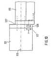
- FIGS. 8 to 10 in particular, the antenna arrangement is described in more detail in the case of a lock cylinder which can be actuated by a knob.
- the in 8 to 10 illustrated lock cylinder has a cylinder housing 111 in which a knob 112 is rotatably mounted about a rotation axis 113.
- the knob can be brought into rotationally fixed connection with a locking lug which actuates a locking bolt.
- the non-rotatable connection can also be permanent or can only be generated or released by a control signal.
- a first antenna 115 is arranged on the knob facing end face 114 of the cylinder housing 111.
- This antenna is in signal communication with a device, not shown, in the cylinder housing, for example an electromechanical coupling, an electrical switch or else with a further antenna 124 on the other end face of the cylinder housing.
- the antenna 115 may be in signal communication with a device outside the cylinder housing.
- the knob 112 is provided on its housing-facing end face 116 with a second antenna 117.
- This antenna is in signal communication with the first antenna 115.
- the arrangement is such that the first and the second antenna have approximately the same distance from the axis of rotation 113. This achieves small transmission distances.
- the second antenna may be formed as a ring antenna along the circumference of the end face 116 of the knob, or located only on a sector of the end face.
- the second antenna 117 may be in communication with an electronic control unit 118. Then, the transmitted signal may be a control signal for an electric element in the cylinder housing. The signal can also be a Decoding signal that has been received by an antenna on the other side of the lock cylinder. The second antenna 117 may also be in signal connection with a third antenna 119 or else with a sensor 120 with which a decoding signal is generated. The control electronics can then be arranged outside this knob. Of course, it is also possible that in the knob next to the second antenna 117, the control electronics 118 and a third antenna 119 and / or a sensor 120 are arranged.
- the electronic modules are activated only when needed.
- the knob is axially movable to switch in a final position, a switching means, or that switches the switching means for activating the control electronics during a rotational movement.
- the other axial end position or rotational position of the knob is held by a spring means in the rest position.
- the activation can also take place in both end positions, and the rest position is a middle position. The power consumption can thus be significantly reduced.
- Fig. 9 an arrangement for signal transmission is shown, in which the cylinder housing is protected by a protective fitting 121.
- an antenna 122 is arranged on the knob 112 facing the top 123 of the protective fitting.
- the antenna 122 is in connection with the lock cylinder, for example via a further antenna arrangement 125 or via a cable connection.
- the antenna on the protective fitting can also be arranged on a detachable insert, which in a appropriate fitting fits.
- the signal transmission can be wireless.
- the first antenna 126 of the lock cylinder 111 is disposed in an intermediate piece 127 which is placed on the end face 114 of the cylinder housing.
- this intermediate piece of the knob 112 fits with the corresponding antenna 117.
- the cooperating antennas 126 and 117 may be formed as a ring antennas along the circumference of the end face, which allow independent of the angular position of the knob signal transmission. This may be useful for some applications. In particular, this makes it possible to always provide an identical raw housing for the lock cylinder, since the choice of the actuating means used remains independent of the design of the housing.
- 127 may be arranged in this intermediate piece conventional slip ring contacts, so that the choice of signal transmission is independent of the design of these assemblies receiving housing.
- the arrangement with external antennas has been described. It is also possible that in the knob on or above the axis of rotation rotating with this an antenna fixed and at or above the protruding into the housing of the lock cylinder portion of the axis of rotation an antenna fixed in the housing, but rotatably arranged relative to the axis of rotation. Both antennas surround the axis of rotation preferably annular.
- the axis of rotation is then at least partially made of a magnetizable material, such as iron or steel, whereby a signal transmission over a longer distance and in particular without losses is possible. Under axis of rotation should be understood here the element over which the Knob is rotatably mounted relative to the cylinder housing.
- the axis of rotation may in this case also include an electronic switching element, for example a clutch.
- the antenna extends from the knob along the axis of rotation into the cylinder housing or is formed by these and cooperates there with a stationary antenna.
Abstract
Description
Die Erfindung betrifft eine Anordnung zur Übertragung eines Dekodierungssignals für einen durch einen Ziehschutzbeschlag geschützten Schließzylinder mit einer Sende-/Empfangseinheit zum kontaktlosen Empfangen eines Dekodierungssignals, die wenigstens ein erstes Sende-/Empfangselement aufweist, das im vorderen Stirnflächenbereich des Schließzylinders angeordnet ist. Der Ziehschutzbeschlag kann als Kernziehschutzbeschlag ausgebildet sein und beispielsweise Bestandteil einer Rosette sein, die lediglich den Bereich des Schließzylinders abdeckt. Auch kann der Ziehschutzbeschlag einen Einsatz vor dem Schließzylinder aufweisen, der auswechselbar sein kann. Es wird im folgenden von einem Ziehschutzbeschlag gesprochen, ohne das dadurch eine Beschränkung auf dessen Ausführung im einzelnen zu verstehen ist. Auch wird im folgenden Sende-/Empfangselement und Antenne synonym verwendet.The invention relates to an arrangement for transmitting a decoding signal for a protected by a Ziehschutzbeschlag lock cylinder with a transmitting / receiving unit for contactless receiving a decoding signal having at least a first transmitting / receiving element which is arranged in the front end face region of the lock cylinder. The pull protection fitting can be designed as core pull protection fitting and, for example, be part of a rosette, which covers only the area of the lock cylinder. Also, the pull protection fitting may have an insert in front of the lock cylinder, which may be interchangeable. It is spoken in the following of a Ziehschutzbeschlag, without thereby a limitation to its execution is to be understood in detail. Also, in the following transmitting / receiving element and antenna used synonymously.
Ein derartiger Schließzylinder mit einem Sende-/Empfangselement auf der Stirnseite des Schließzylinders ist beispielsweise aus der
Die
Das kontaktlos übertragene Dekodierungssignal dient zum Schalten eines elektrisch wirksamen Antriebselements, Kupplungselements, End- oder Verriegelungselements, um ein Betätigen des Schließzylinders zu ermöglichen. Andererseits wird das Dekodierungssignal häufig dazu verwendet, um sogenannte Zutrittskontrollsysteme zu schaffen, mit welchem die einzelnen Schließvorgänge kontrolliert und registriert werden können. Wegen der erforderlichen Antennenanordnung auf der Stirnfläche und der fehlenden Möglichkeit des Schutzes des Schließzylinders gegen Herausziehen besitzen solche elektromechanisch arbeitenden Schließzylinder nur eine relativ geringe mechanische Sicherheit. Es besteht jedoch häufig der Wunsch, auch solche elektromechanischen Schließzylinder beispielsweise im Außenbereich anzuordnen, in dem eine erhöhte mechanische Sicherheit gefordert ist.The contactlessly transmitted decoding signal serves to switch an electrically effective drive element, coupling element, end or locking element in order to enable actuation of the lock cylinder. On the other hand, the decoding signal is often used to provide so-called access control systems, with which the individual closing operations can be controlled and registered. Because of the required antenna arrangement on the end face and the lack of possibility of protection of the lock cylinder against pulling such electromechanically operating lock cylinder have only a relatively low mechanical safety. However, there is often the desire to arrange such electromechanical lock cylinder, for example, outdoors, in which an increased mechanical safety is required.
Neben solchen Schließzylindern, die mit einem Schlüssel betätigt werden, sind sogenannte Knaufzylinder bekannt, die von wenigstens einer Seite mit einem Knauf betätigbar sind. In einem solchen Knauf ist häufig die Steuerelektronik zum Auswerten des Transpondersignals angeordnet, das mit einem Schlüssel der oben beschriebenen Art übermittelt wird. Eine solche Anordnung ist beispielsweise in der
Auch bei Knaufzylindern ist es häufig erwünscht und teilweise auch erforderlich, daß die Betätigung erst nach dem Erhalt eines entsprechenden Dekodierungssignals möglich ist. Bei solchen Schließzylindern ist das Dekodierungsgerät häufig mit Abstand zum Schließzylinder angeordnet, beispielsweise im Bereich der Türzarge. Das Dekordierungsgerät kann ein Tastenfeld oder mit einem biometrischen Sensor ausgestattet sein oder aber über ein Dekodierungselement, beispielsweise einen Schlüssel oder eine Chipkarte, bedient werden. Zum Öffnen wird dann der Knauf mit der anderen Hand betätigt. Dies erfordert jedoch einen größeren Montageaufwand des Schließzylinders und des damit in Verbindung stehenden Dekodierungsgeräts.Even with Knaufzylindern it is often desirable and sometimes necessary that the operation is possible only after receiving a corresponding decoding signal. In such locking cylinders, the decoding device is often arranged at a distance from the lock cylinder, for example in the region of the door frame. The Dekordierungsgerät may be a keypad or equipped with a biometric sensor or via a decoding element, such as a key or a smart card operated. To open the knob is then operated with the other hand. However, this requires a greater installation effort of the lock cylinder and the associated decoding device.
Aufgrund der immer kleiner bauenden Elektronik können die Steuerelektronik und auch der Dekodierungssensor, beispielsweise die Transponderantenne oder ein biometrischer Sensor, für solche elektromechanisch arbeitenden Schließzylinder in dem Knauf untergebracht werden. Das Problem bei solchen Knaufzylindern besteht dann in der Signalübertragung von dem feststehenden Schließzylinderteil zum drehbaren Knauf.Due to the ever-smaller electronics, the control electronics and the decoding sensor, such as the transponder antenna or a biometric sensor, can be accommodated for such electromechanically operating lock cylinder in the knob. The problem with such Knaufzylindern then consists in the signal transmission from the fixed lock cylinder part to the rotatable knob.
Der Erfindung liegt daher die Aufgabe zu Grunde, einen Schließzylinder der eingangs geschilderten Art so auszubilden, daß eine kontaktlose Übertragung des Dekodierungssignals bei einem vorhandenen Ziehschutzbeschlag und auch bei einem Knauf möglich ist.The invention is therefore based on the object, a lock cylinder of the type described in such a way that a contactless transmission of the decoding signal in an existing Ziehschutzbeschlag and even a knob is possible.
Die Aufgabe wird gemäß der Erfindung in einer ersten Ausführungsform dadurch gelöst, daß ein zweites Sende-/Empfangselement auf der Vorderseite des Ziehschutzbeschlages angeordnet ist, das in Signalverbindung mit einem dritten Sende-/Empfangselement auf der Rückseite des Ziehschutzbeschlages steht, das in Signalverbindung mit dem ersten Sende-/Empfangselement auf der Stirnseite des Schließzylinders steht. Dadurch wird erreicht, daß das Dekodierungssignal von dem äußeren Sende-/Empfangselement über zwei weitere Sende-/Empfangselemente zur Sende-/Empfangseinheit geleitet wird. Die Verbindung zwischen den beiden auf dem Ziehschutzbeschlag angeordneten Sende-/Empfangselementen kann beispielsweise durch ein Signalkabel erfolgen, das durch eine Bohrung oder Nut geführt ist. Diese Bohrung oder Nut bewirkt nur eine geringe Schwächung des Ziehschutzbeschlages, so daß dessen Schutzfunktion vollständig aufrechterhalten bleiben kann.The object is achieved according to the invention in a first embodiment, characterized in that a second transmitting / receiving element is arranged on the front of the pull protection fitting, which is in signal communication with a third transmitting / receiving element on the back of the pull protection fitting, in signal communication with the first transmitting / receiving element is on the front side of the lock cylinder. This ensures that the decoding signal is passed from the outer transmitting / receiving element via two further transmitting / receiving elements to the transmitting / receiving unit. The connection between the two on the pull protection fitting arranged transmitting / receiving elements can be done for example by a signal cable, which is guided through a hole or groove. This bore or groove causes only a small weakening of the pull protection fitting, so that its protective function can be completely maintained.
Die erforderliche Bohrung oder Nut kann vorzugsweise außerhalb des Bereiches des Ziehschutzbeschlages angeordnet sein, der den Schließzylinder überdeckt. Dadurch wird erreicht, daß ein Ansatzpunkt eines Ziehwerkzeuges, das in die Bohrung oder Nut eingreifen könnte, außerhalb des Bereiches liegt, in dem ein Ziehen des Schließzylinders aus der Tür oder dergleichen möglich wäre.The required bore or groove may preferably be arranged outside the region of the pull protection fitting, which covers the lock cylinder. It is thereby achieved that a starting point of a drawing tool, which could engage in the bore or groove, is outside the range in which a pulling of the lock cylinder out of the door or the like would be possible.
Es ist zweckmäßig, wenn das Sende-/Empfangselement auf der Vorderseite des Ziehschutzbeschlages zumindest teilweise in dem Bereich angeordnet ist, der den Schließzylinder überdeckt. Hierdurch wird erreicht, daß bei der Verwendung eines aktiven oder passiven Senders am Schlüsselgriff der erforderliche geringe abstand eingehalten werden kann. Es kann aber auch vorgesehen werden, daß das Sende-/Empfangselement auf der Vorderseite des Ziehschutzbeschlages in dem den Schließzylinders zumindest teilweise umgebenden Bereich angeordnet ist. Auch hierdurch kann ein geringer Abstand zum aktiven oder passiven Sender des Schlüssels oder eines anderen Dekodierelementes erreicht werden.It is expedient if the transmitting / receiving element is arranged on the front of the pull protection fitting at least partially in the area which covers the lock cylinder. This ensures that when using an active or passive transmitter on the key handle the required small distance can be maintained. But it can also be provided that the transmitting / receiving element is arranged on the front side of the pull protection fitting in the area surrounding the lock cylinder at least partially. This also allows a small distance to the active or passive transmitter of the key or another decoding element can be achieved.
Grundsätzlich kann das Sende-/Empfangselement auf dem Ziehschutzbeschlag angeordnet sein. Es ist jedoch zweckmäßig, wenn das Sende-/Empfangselement auf der Vorderseite des Ziehschutzbeschlages in einer Vertiefung angeordnet ist derart, daß zwischen Schließzylinder und Bodenfläche der Vertiefung noch ausreichend Material vorhanden ist. Das Sende-/Empfangselement schließt dabei vorzugsweise bündig mit der Oberfläche des Ziehschutzbeschlages ab, so daß zum einen an ansprechendes Äußeres erreicht wird. Zum anderen wird eine versehentliche oder absichtliche Zerstörung des Sende-/Empfangselementes wirksam verhindert.In principle, the transmitting / receiving element can be arranged on the pull protection fitting. However, it is expedient if the transmitting / receiving element is arranged on the front of the pull protection fitting in a recess such that between lock cylinder and bottom surface of the recess still sufficient material is present. The transmitting / receiving element preferably terminates flush with the surface of the pull-protection fitting, so that, on the one hand, an appealing appearance is achieved. On the other hand, an accidental or deliberate destruction of the transmitting / receiving element is effectively prevented.
Vorstehend wurde die Erfindung anhand eines Schließzylinders beschrieben, dessen Schließkern mittels eines Schlüssels zu betätigen ist. Hierbei ist das Vorsehen eines Ziehschutzbeschlages häufig erforderlich. Im wesentlichen das gleiche Problem tritt jedoch auch bei einem Schließzylinder auf, dessen Schließnase mit einem Knauf zu betätigen ist. Auch hier ist es häufig erwünscht und teilweise auch erforderlich, daß die Betätigung erst nach dem Empfang eines entsprechenden Dekodierungssignals möglich ist. Bei solchen Schließzylindern ist das Sende-/Empfangselement zum Empfangen des Dekodierungssignals häufig mit Abstand zum Schließzylinder angeordnet, beispielsweise im Bereich der Türzarge in einem Dekodiergerät. Das Dekodierungselement, beispielsweise ein Schlüssel oder eine Chipkarte, wird in den Bereich des Sende-/Empfangselements gehalten, während gleichzeitig der Knauf mit der anderen Hand betätigt wird. Dies erfordert jedoch einen größeren Montageaufwand des Schließzylinders und des damit in Verbindung stehenden Sende-/Empfangselements.Above, the invention has been described with reference to a lock cylinder whose lock core is to be operated by means of a key. Here, the provision of a pull protection fitting is often required. However, substantially the same problem also occurs in a lock cylinder whose locking lug is to be operated with a knob. Again, it is often desirable and sometimes necessary that the operation only after receiving a corresponding decoding signal is possible. In such locking cylinders, the transmitting / receiving element for receiving the decoding signal is often arranged at a distance from the lock cylinder, for example in the region of the door frame in a decoding device. The decoding element, for example a key or a chip card, is held in the area of the transmitting / receiving element, while at the same time the knob is operated with the other hand. However, this requires a larger installation effort of the lock cylinder and the associated transmitting / receiving element.
Die erfindungsgemäße Anordnung zur Übertragung des Dekodierungssignals für einen mit einem Knauf zu betätigenden Schließzylinder mit einer Sende-/Empfangseinheit zum kontaktlosen Empfangen des Dekodierungssignals weist wenigstens ein erstes Sende-/Empfangselement auf, das im vorderen Stirnflächenbereich des Schließzylinders angeordnet ist. Insoweit entspricht das Schließzylindergehäuse auch dem eines Schließzylinders, der mit einem Schlüssel zu betätigen ist. Gemäß der Erfindung ist hier vorgesehen, daß ein äußeres Sende-/Empfangselement auf dem Knauf angeordnet ist, das in Signalverbindung mit einem Sende-/Empfangselement auf der dem Schließzylinder zugekehrten Stirnseite des Knaufs steht, das in Signalverbindung mit dem ersten Sende-/Empfangselement auf der Stirnseite des Schließzylinders steht. Auch hierdurch kann erreicht werden, daß durch einen in den Empfangs- oder Sendebereich des äußeren Sende-/Empfangselements gebrachten aktiven oder passiven Sender das Dekodierungssignal zur Sende-/Empfangseinheit übertragen wird. Es wird, wie auch bei der Ausführungsform mit Ziehschutzbeschlag, das Signal über zwei weitere Sende-/Empfangselemente übertragen. Insgesamt wird hierdurch bewirkt, daß auch ein mit einem Knauf zu betätigender Schließzylinder mit einer elektronischen Dekodierung in jede Aufnahme für einen Normschließzylinder paßt. Weitere Montagevorgänge, insbesondere das räumlich vom Schließzylinder getrennte Anordnen eines Sende-/Empfangselementes, entfallen.The arrangement according to the invention for transmitting the decoding signal for a locking cylinder to be operated with a knob with a transmitting / receiving unit for contactless receiving of the decoding signal has at least one first transmitting / receiving element, which is arranged in the front end face region of the locking cylinder. In that regard, the lock cylinder housing also corresponds to that of a lock cylinder, which is operated with a key. According to the invention it is provided here that an outer transmitting / receiving element is arranged on the knob, which is in signal communication with a transmitting / receiving element on the lock cylinder facing the front side of the knob, in signal communication with the first transmitting / receiving element the front side of the lock cylinder is. This also makes it possible to achieve that the decoding signal is transmitted to the transmitting / receiving unit by means of an active or passive transmitter placed in the receiving or transmitting area of the outer transmitting / receiving element. It is, as in the embodiment with pull protection fitting, the signal via two other transmitting / receiving elements transfer. Overall, this has the effect that even with a knob to be operated lock cylinder with an electronic decoding fits into any receptacle for a standard lock cylinder. Further assembly operations, in particular the spatially separated from the lock cylinder arranging a transmitting / receiving element, omitted.
Das Dekodierungssignal wird vorzugsweise mittels elektromagnetischer Wellen übertragen. Es können aber auch optische, akustische oder induktive Signalübertragungsverfahren eingesetzt werden. Wesentlich ist, daß die entsprechenden Sende-/Empfangselemente entsprechend ihrer Übertragungsart an den betreffenden Bauelementen angeordnet sind. Insbesondere bei der Verwendung von elektromagnetischen Wellen ist es zweckmäßig, wenn auf dem Dekodierelement, also insbesondere auf einem Schlüssel oder einer Chipkarte, ein passiver Transponder angeordnet ist, der von einer Sende-/Empfangseinheit des Schließzylinders angeregt wird. Dies hat zum einen den Vorteil, daß der Schlüssel ohne Energieversorgung ausgebildet sein kann. Ferner wird gewährleistet, daß das Sende-/Epfangselement am Schließzylinder mit ausreichender Leistung betrieben werden kann. Dadurch ist die Signalübertragung auch über mehrere kontaktlose Übertragungsstrecken ohne weiteres möglich. Insgesamt kann dadurch ein zuverlässiges Arbeiten des Schließzylinders bewirkt werden.The decoding signal is preferably transmitted by means of electromagnetic waves. However, it is also possible to use optical, acoustic or inductive signal transmission methods. It is essential that the corresponding transmitting / receiving elements are arranged according to their transmission to the relevant components. In particular, when using electromagnetic waves, it is expedient if a passive transponder is arranged on the decoding element, that is to say in particular on a key or a chip card, which is excited by a transmitting / receiving unit of the lock cylinder. This has the advantage that the key can be designed without power supply. Furthermore, it is ensured that the transmitting / Epfangselement can be operated on the lock cylinder with sufficient power. As a result, the signal transmission over a plurality of contactless transmission links readily possible. Overall, this can be a reliable operation of the lock cylinder causes.
Wo im einzelnen die Antennen beziehungsweise die Sende-/Empfangselemente angeordnet sind, ist grundsätzlich beliebig. Die Sende-/Empfangselemente können auch in einer Sende-/Empfangseinrichtung integriert sein. Zweckmäßig ist es, wenn das erste Sende-/Empfangselement im vorderen Stirnflächenbereich des Gehäuses des Schließzylinders angeordnet ist. Dabei ist es weiterhin günstig, wenn das zweite Sende-/Empfangselemente auf der dem Schließzylinder zugekehrten Stirnfläche des Knaufs angeordnet ist. Weiterhin kann es hier besonders vorteilhaft sein, wenn das erste und zweite Sende-/Empfangselement einen in etwa gleichen Abstand zur Drehachse aufweisen. Durch diese Maßnahmen werden kurze Signalübertragungsstrecken erreicht, so daß nur geringe Sendeleistungen erforderlich werden. Dies ist aufgrund der häufig verwendeten netzunabhängigen Stromversorgung solcher Schließzylinder zweckmäßig.Where in detail the antennas or the transmitting / receiving elements are arranged is basically arbitrary. The transmitting / receiving elements can also be integrated in a transmitting / receiving device. It is expedient if the first transmitting / receiving element in the front end face area of the housing of the lock cylinder is arranged. It is also advantageous if the second transmitting / receiving elements is arranged on the closing cylinder facing end face of the knob. Furthermore, it may be particularly advantageous if the first and second transmitting / receiving element have an approximately equal distance from the axis of rotation. By these measures short signal transmission distances are achieved, so that only low transmission powers are required. This is due to the frequently used off-grid power supply such lock cylinder appropriate.
Das erste Sende-/Empfangselement kann unmittelbar mit dem Gehäuse des Zylinders verbunden sein. Grundsätzlich kann aber auch vorgesehen werden, daß das erste Sende-/Empfangselement in einem Zwischenstück angeordnet ist, das auf das Gehäuse des Schließzylinders aufsetzbar ist. Dies hat den Vorteil, daß die zusammenwirkenden ersten und zweiten Sende-/Empfangselemente stets auf einer identischen Baugruppe vorhanden sind, während das Gehäuse des Schließzylinders an die unterschiedlichen Bedingungen, insbesondere an unterschiedliche Einbaulängen angepaßt werden kann. Der Herstellungsaufwand wird somit verringert.The first transmitting / receiving element can be connected directly to the housing of the cylinder. In principle, however, it can also be provided that the first transmitting / receiving element is arranged in an intermediate piece which can be placed on the housing of the lock cylinder. This has the advantage that the cooperating first and second transmitting / receiving elements are always present on an identical assembly, while the housing of the lock cylinder can be adapted to the different conditions, in particular to different installation lengths. The production cost is thus reduced.
Weiterhin ist es möglich, daß das mit dem Sende-/Empfangselement am Knauf zusammenwirkende Sende-/Empfangselement auf einem Schutzbeschlag des Schließzylinders angeordnet ist. Dieses Sende-/Empfangselement kann in Signalverbindung mit einer weiteren Einrichtung im Schließzylinder drahtgebunden oder drahtlos in Verbindung stehen.Furthermore, it is possible that the transmitting / receiving element cooperating with the transmitting / receiving element on the knob is arranged on a protective fitting of the lock cylinder. This transmitting / receiving element can be in wired connection with a further device in the lock cylinder or in wireless communication.
Welche Signale über diese Antennenanordnung übertragen werden, ist grundsätzlich beliebig. Es kann vorgesehen werden, daß das äußere Sende-/Empfangselement am Knauf mit einer Steuerelektronik im Knauf zusammenwirkt. Auch kann das Sende-/Empfangselement mit einem Sensor zum Erfassen eines Dekodierungssignals zusammenwirken. Dieser Sensor kann ein biometrischer Sensor oder eine Antenne für ein Transondersystem sein. Es kann vorgesehen werden, daß im Knauf ein Teil eines aktiven Übertragungssystems, beispielsweise ein Signalverstärker oder dergleichen angeordnet ist. Damit wird die Signalübertragung noch zuverlässiger.Which signals are transmitted via this antenna arrangement is basically arbitrary. It can be provided that the outer transmitting / receiving element on the knob cooperates with control electronics in the knob. Also, the transmitting / receiving element may cooperate with a sensor for detecting a decoding signal. This sensor may be a biometric sensor or an antenna for a transponder system. It can be provided that a part of an active transmission system, such as a signal amplifier or the like is arranged in the knob. This makes the signal transmission even more reliable.
Grundsätzlich kann der Schließzylinder auf beiden Stirnseiten mit Sende-/Empfangselementen versehen sein. Es entsteht ein symmetrisches Zylindergehäuse, daß ohne großen Aufwand herstellbar ist und gelagert werden kann. Insbesondere ist es möglich, ein gleiches Rohgehäuse für beide Seiten vorzusehen, unabhängig davon ob ein erstes Sende-/Empfangselemente am Gehäuse vorgesehen wird und welches Betätigungsmittel damit zusammenwirkt. Auch kann die Einbaulänge ohne weiteres durch Verlängerungen beliebig variiert werden.In principle, the lock cylinder can be provided on both end sides with transmitting / receiving elements. The result is a symmetrical cylinder housing that can be produced without great effort and can be stored. In particular, it is possible to provide an identical raw housing for both sides, regardless of whether a first transmitting / receiving elements is provided on the housing and which actuating means cooperates therewith. Also, the installation length can be easily varied by extensions as desired.
Die Erfindung wird im folgenden anhand der schematischen Zeichnung näher erläutert. Es zeigen:
- Fig. 1
- die Seitenansicht eines Schließzylinders mit einem Ziehschutzbeschlag mit einer Signalübertragungsanordnung gemäß der Erfindung in auseinandergezogener Darstellung,
- Fig. 2
- die Seitenansicht eines Schließzylinders mit einem Ziehschutzbeschlag gemäß einer anderen Ausführungsform in auseinandergezogener Darstellung,
- Fig. 3
- die Vorderansicht auf einen Ziehschutzbeschlag mit einer Signalübertragungsanordnung gemäß Fig. 1 oder Fig. 2,
- Fig. 4
- die Seitenansicht eines Schließzylinders mit einem Drehknauf und einer Signalübertragungsanordnung gemäß der Erfindung,
- Fig. 5
- die Vorderansicht des Drehknaufs gemäß Fig. 4,
- Fig. 6
- die Draufsicht auf die dem Schließzylinder zugekehrte Seite des Drehknaufs gemäß Fig. 4,
- Fig. 7
- die Draufsicht auf einen Schließzylinder,
- Fig. 8
- die Seitenansicht eines Schließzylinders mit einem Knauf und einer Signalübertragungsanordnung gemäß der Erfindung,
- Fig. 9
- die Seitenansicht auf einen Schließzylinder und einem Knauf mit Ziehschutzbeschlag gemäß der Erfindung und
- Fig. 10
- die Seitenansicht eines Schließzylinders gemäß einer weiteren Ausführungsform der Erfindung.
- Fig. 1
- the side view of a lock cylinder with a pull protection fitting with a signal transmission arrangement according to the invention in an exploded view,
- Fig. 2
- the side view of a lock cylinder with a pull protection fitting according to another embodiment in an exploded view,
- Fig. 3
- 1 is a front view of a pull protection fitting with a signal transmission arrangement according to FIG. 1 or FIG. 2, FIG.
- Fig. 4
- the side view of a lock cylinder with a rotary knob and a signal transmission arrangement according to the invention,
- Fig. 5
- the front view of the rotary knob of FIG. 4,
- Fig. 6
- the top view of the lock cylinder facing side of the rotary knob of FIG. 4,
- Fig. 7
- the top view of a lock cylinder,
- Fig. 8
- the side view of a lock cylinder with a knob and a signal transmission arrangement according to the invention,
- Fig. 9
- the side view of a lock cylinder and a knob with pull protection fitting according to the invention and
- Fig. 10
- the side view of a lock cylinder according to another embodiment of the invention.
Der in den Figuren 1 und 2 dargestellte Schließzylinder 11 weist eine zylindrische Aufnahme 12 für einen Schließkern auf, der mit nicht gezeigten Schließstiften zusammenwirkt. Diese Schließstifte werden bei der Einführung des mechanisch passenden Schlüssels entriegelt, so daß der Schließkern zur Betätigung der nicht gezeigten Schließnase gedreht werden kann. Insoweit entspricht der Schließzylinder einem herkömmlichen mechanischen Schließzylinder und bedarf keiner weiteren Erläuterung.The
Zum kontaktlosen Übertragen eines Dekodierungssignals, mit dem ein nicht gezeigtes elektronisch arbeitendes Antriebselement, Kupplungselement, Fern- oder Endriegelungselement geschaltet werden kann, ist auf der vorderen Stirnfläche 13 des Schließzylinders ein Sende-/Empfangselement 14 angeordnet, das mit einer nicht gezeigten Sende-/Empfangseinheit des Schließzylinders zusammenwirkt. Diese Sende-/Empfangseinheit kann in dem Schließzylinder oder in einem Knauf auf der der Schließseite abgekehrten Seite des Schließzylinders angeordnet sein. Eine solche Anordnung ist beispielsweise aus der
Ein derartiger Schließzylinder kann, sofern er in einem normalen Türbeschlag eingebaut ist, mit einem Schlüssel betätigt werden, der einen entsprechenden passiven oder aktiven Sender im Schlüsselgriff trägt. Es ist offensichtlich, daß bei der Verwendung eines Ziehschutzbeschlages, der gerade die Stirnfläche 13 des Schließzylinders 11 überdeckt, eine kontaktlose Signalübertragung nicht mehr ohne weiteres möglich ist.Such a lock cylinder, if it is installed in a normal door fitting, be operated with a key that carries a corresponding passive or active transmitter in the key handle. It is obvious that in the use of a pull protection fitting, which just covers the
Bei dem in der Zeichnung dargestellten Ausführungsform der Signalübertragungsanordnung weist der Ziehschutzbeschlag 15, der über den Schließzylinder 11 montiert wird, ein zweites Sende-/Empfangselement 16 auf. Im einzelnen ist die Anordnung so getroffen, daß das zweite Sende-/Empfangselement 16 in einer Vertiefung 17 des Ziehschutzbeschlages 15 in einem Bereich eingelassen ist, der dem feststehenden Steg 18 des Schließzylinders 11 überdeckt. Das zweite Sende-/Empfangselement besitzt demnach die gleiche relative Position zum Schlüssel wie das unmittelbar am Schließzylinder 11 angeordnete Sende-/Empfangselement 14. Dementsprechend weist der aktive oder passive Sender eines Schlüssels im eingesteckten Zustand den erforderlichen geringen Abstand zur kontaktlosen Signalübertragung auf.In the embodiment of the signal transmission arrangement shown in the drawing, the pull protection fitting 15, which is mounted on the
Bei dem in Figur 1 dargestellten Ausführungsbeispiel steht das auf der Vorderseite 19 des Ziehschutzbeschlages 15 angeordnete Sende-/Empfangselement über ein Signalkabel 22 in Verbindung mit einem dritten Sende-/Empfangselement 20 auf der Rückseite 21 des Ziehschutzbeschlages 15. Dieses dritte Sende-/Empfangselement steht in kontaktloser Signalübertragungsverbindung mit dem Sende-/Empfangselement 14 auf der vorderen Stirnfläche 13 des Schließzylinders. Damit wird eine Signalübertragung vom aktiven oder passiven Sender des Schlüssels über das zweite Sende-/Empfangselement 16, das Signalkabel 22, das dritte Sende-/Empfangselement 20 und das Sende-/Empfangselement 14 am Schließzylinder 11 zur auswertenden Sende-/Empfangseinheit des Schließzylinders bewirkt. Es ist offensichtlich, daß die Schutzfunktion des Ziehschutzbeschlages 15 nach wie vor aufrecht erhalten bleibt, da der Bereich des Schließzylinders von Material, insbesondere von metallischem Material, überdeckt ist. Bei dem in der Zeichnung dargestellten Ausführungsbeispiel ist das Signalkabel 22 in der kürzesten Verbindung zwischen den beiden in einer Flucht liegenden Sende-/Empfangselementen 16, 20 durch eine Bohrung 23 geführt. Es ist selbstverständlich auch möglich, daß das Signalkabel in Bohrungen oder Nuten um den Bereich herumgeführt wird, der den Schließzylinder 11 überdeckt. Diese Möglichkeit ist in der Zeichnung gestrichelt dargestellt.In the embodiment shown in Figure 1, arranged on the
Bei der in Figur 2 dargestellten Ausführungsform ist der Schließzylinder 11 nicht mit einem eigenen Sende-/Empfangselement auf der vorderen Stirnseite 13 versehen. Hier ist die Anordnung so getroffen, daß das Sende-/Empfangselement 16 auf der Vorderseite 19 des Ziehschutzbeschlages 15 über ein Signalkabel 24 unmittelbar in Verbindung mit der Sende-/Empfangseinheit des Schließzylinders steht. Im einzelnen ist die Anordnung so getroffen, daß das Signalkabel 24 mit Kontakten 25 auf der Rückseite 21 des Ziehschutzbeschlages 15 verbunden ist, die ihrerseits mit korrespondierenden Kontakten 26 auf der vorderen Stirnfläche 13 des Schließzylinders 11 zusammenwirken. Die Kontakte sind hierbei so ausgebildet und bemessen, daß bei der Montage des Ziehschutzbeschlages 15 die erforderliche Verbindung zur Signalübertragung erzeugt wird. Die Kontakte können beispielsweise als Federstifte oder als Stecker- Kupplungsanordnung ausgebildet sein.In the embodiment shown in Figure 2, the
In Figur 4 ist eine andere Ausführungsform eines Schließzylinders dargestellt. Der Schießzylinder 11 entspricht hinsichtlich der Ausführung des Gehäuses demjenigen gemäß Figur 1, und es sind gleiche oder gleichwirkende Elemente mit gleichen Bezugszeichen versehen. Hier ist die Anordnung jedoch so getroffen, daß die Schließnase nicht über einen mechanischen Schlüssel sondern über ein Drehknauf 27 betätigbar ist. Bei Empfang des richtigen Dekodierungssignals schaltet ein elektrisch oder elektronisch arbeitendes Antriebselement, Kupplungselement, Ver- oder Entriegelungselement, so daß die Betätigung der Schließnase über den Drehknauf 27 möglich ist.FIG. 4 shows another embodiment of a lock cylinder. The
Um die kontaktlose Übertragung des Dekodierungssignals zu ermöglichen, weist der Drehknauf 27 ein äußeres zweites Sende-/Empfangselement 28 auf, das beispielsweise auf der Vorderseite des Drehknaufs 29 angeordnet ist. Das Sende-/Empfangselement 28 kann, wie gezeigt, als ringförmige Antenne oder als plattenförmige Antenne 28' ausgebildet sein, die beispielsweise im mittleren Bereich der Vorderfläche 29 des Knaufs 27 angeordnet ist. Dies ist in der Zeichnung gestrichelt dargestellt. Das Sende-/Empfangselement 28, 28' steht in Signalverbindung mit einem dritten Sende-/Empfangselement 30, das auf der dem Schließzylinder 11 zugekehrten Seite 31 des Knaufs 27 angeordnet ist. Dieses Sende-/Empfangselement 30 ist vorzugsweise als ringförmige Antenne ausgebildet, deren Radius so bemessen ist, daß unabhängig von der Drehstellung des Knaufs 27 stets eine Übertragung des Dekodierungssignals zum Sende-/Empfangselement 14 am Schließzylinder 11 möglich ist. Durch diese Anordnung wird eine kontaktlose Übertragung des Dekodierungssignal von einem aktiven oder passiven Sender eines Dekodierungelementes über das äußere, zweite Sende-/Empfangselement 28, ein Signalkabel 32, das innere, dritte Sende-/Empfangselement 30 und das Sende-/Empfangselement 14 zur auswertenden Sende-/Empfangseinheit des Schließzylinders bewirkt.In order to enable the contactless transmission of the decoding signal, the
Die Sende-/Empfangselemente 14, 16, 20, 28, 28' 30 können als Spulenantennen beispielsweise aus Kupferdraht ausgebildet sein, die vorzugsweise in entsprechenden Kunststoffelementen in Ausnehmungen der betreffenden Bauteile gehalten sind. Auch ist es möglich die Antennen in einer Vergußmaße in der Ausnehmung zu halten. Entsprechendes gilt für die Kontakte 25, 26 bei der Ausführungsform gemäß Fig. 2.The transmitting / receiving
Die vorstehenden Ausführungsbeispiele zeigen einen Schließzylinder entweder in Kombination mit einem Ziehschutzbeschlag oder einem Knauf. Es ist natürlich auch möglich, daß ein Knauf und ein Ziehschutzbeschlag zusammen mit dem Schließzylinder montiert werden. Anstelle eines Schließkerns wird dementsprechend der Knauf 27 in der zylindrischen Aufnahme 12 des Schließzylinders montiert. Die Signalübertragung erfolgt dann von dem äußeren Sende-/Emfangselement 28 über das innnenliegende Sende-/Empfangselement 30 des Knaufs zum Sende-/Empfangselement 16 des Ziehschutzbeschlages. Dort kann das Signal unmittelbar gemäß Fig. 2 oder über die weiteren Sende-/Empfangselemente 20, 14 zur Sende-/Empfangseinheit des Schließzylinders übertragen werden. Grundsätzlich kann auch bei dieser Ausführungsform das Signal vom Knauf mittels eines Schleifrinkontaktes zum Schließzylinder übertragen werden.The above embodiments show a lock cylinder either in combination with a pull protection fitting or a knob. It is of course also possible that a knob and a pull protection fitting are mounted together with the lock cylinder. Instead of a lock core, the
Aus den Ausführungsbeispielen gemäß Figur 1 und Figur 4 wird deutlich, daß stets das gleiche Schließzylindergehäuse für beide Ausführungen verwendet werden kann. Auch ist es möglich, daß die Kontakte 26 beziehungsweise das Sende-/Empfangselement 14 so ausgebildet sind oder so in einer entsprechenden Ausnehmung des Schließzylindergehäuses angeordnet sind, daß auch die Ausführungsform gemäß Figur 2 mit dem gleichen Schließzylindergehäuse hergestellt werden kann. Auch können genormte Zylinderformen, wie Euro-Profilzylinder, Oval-Profilzylinder oder Rund-Profilzylinder, verwendet werden. Insgesamt läßt sich dadurch der Herstellungsaufwand verringern.From the embodiments of Figure 1 and Figure 4 it is clear that always the same lock cylinder housing can be used for both versions. It is also possible that the
In den Fig. 8 bis 10 wird insbesondere die Antennenanordnung bei einem durch einen Knauf betätigbaren Schließzylinder näher beschrieben. Der in den Fig. 8 bis 10 dargestellte Schließzylinder weist ein Zylindergehäuse 111 auf, in dem ein Knauf 112 um eine Drehachse 113 drehbar gelagert ist. Der Knauf kann in drehfeste Verbindung mit einer Schließnase gebracht werden, die einen Schließriegel betätigt. Die drehfeste Verbindung kann auch permanent sein oder aber erst durch ein Steuersignal erzeugt oder freigegeben werden.In FIGS. 8 to 10, in particular, the antenna arrangement is described in more detail in the case of a lock cylinder which can be actuated by a knob. The in 8 to 10 illustrated lock cylinder has a
Auf der dem Knauf zugekehrten Stirnfläche 114 des Zylindergehäuses 111 ist eine erste Antenne 115 angeordnet. Diese Antenne steht in Signalverbindung mit einer nicht gezeigten Einrichtung im Zylindergehäuse, beispielsweise einer elektromechanischen Kupplung, einem elektrischen Schalter oder aber auch mit einer weiteren Antenne 124 auf der anderen Stirnseite des Zylindergehäuses. Auch kann die Antenne 115 mit einer Einrichtung außerhalb des Zylindergehäuses in Signalverbindung stehen.On the knob facing
Der Knauf 112 ist auf seiner dem Gehäuse zugekehrten Stirnfläche 116 mit einer zweiten Antenne 117 versehen. Diese Antenne steht in Signalverbindung mit der ersten Antenne 115. Im einzelnen ist die Anordnung so getroffen, daß die erste und die zweite Antenne in etwa den gleichen Abstand zur Drehachse 113 aufweisen. Dadurch werden kleine Übertragungstrecken erreicht. Die zweite Antenne kann, wie in Fig. 6 dargestellt, als Ringantenne entlang dem Umfang der Stirnfläche 116 des Knaufs ausgebildet sein, oder sich nur auf einem Sektor der Stirnfläche befinden.The
Die zweite Antenne 117 kann in Verbindung mit einer Steuerelektronik 118 stehen. Dann kann das übertragene Signal ein Steuersignal für ein elektrisches Element im Zylindergehäuse sein. Das Signal kann aber auch ein Dekodierungssignal sein, das von einer Antenne auf der anderen Seite des Schließzylinders empfangen worden ist. Auch kann die zweite Antenne 117 mit einer dritten Antenne 119 oder aber mit einem Sensor 120 in Signalverbindung stehen, mit dem ein Dekodierungsignal erzeugt wird. Die Steuerelektronik kann dann außerhalb dieses Knaufs angeordnet sein. Selbstverständlich ist es auch möglich, daß in dem Knauf neben der zweiten Antenne 117 die Steuerelektronik 118 und eine dritte Antenne 119 und/oder ein Sensor 120 angeordnet sind.The
Insbesondere bei einem Schließzylinder, der die Steuerelektronik und die Sensorik aufweist und netzunabhängig arbeitet, ist es zweckmäßig, daß die elektronischen Baugruppen erst bei Bedarf aktiviert werden. Dazu kann vorgesehen werden, daß der Knauf axial beweglich ist, um in einer Endstellung ein Schaltmittel zu schalten, oder daß bei einer Drehbewegung das Schaltmittel zum Aktivieren der Steuerelektronik schaltet. In der anderen axialen Endstellung oder Drehstellung wird der Knauf durch ein Federmittel in der Ruhelage gehalten. Die Aktivierung kann auch in beiden Endstellungen erfolgen, und die Ruhelage eine mittlere Position ist. Der Stromverbrauch kann damit deutlich reduziert werden.In particular, in a lock cylinder, which has the control electronics and sensors and works independently of the mains, it is expedient that the electronic modules are activated only when needed. For this purpose, it may be provided that the knob is axially movable to switch in a final position, a switching means, or that switches the switching means for activating the control electronics during a rotational movement. In the other axial end position or rotational position of the knob is held by a spring means in the rest position. The activation can also take place in both end positions, and the rest position is a middle position. The power consumption can thus be significantly reduced.
In Fig. 9 ist eine Anordnung zur Signalübertragung gezeigt, bei welcher das Zylindergehäuse durch einen Schutzbeschlag 121 geschützt ist. Hier ist eine Antenne 122 auf der dem Knauf 112 zugekehrten Oberseite 123 des Schutzbeschlages angeordnet. Die Antenne 122 steht in Verbindung mit dem Schließzylinder beispielsweise über eine weitere Antennenanordnung 125 oder über eine Kabelverbindung. Die Antenne am Schutzbeschlag kann auch auf einem lösbaren Einsatz angeordnet sein, der in einen entsprechenden Beschlag paßt. Trotz des Schutzbeschlages kann die Signalübertragung drahtlos erfolgen.In Fig. 9, an arrangement for signal transmission is shown, in which the cylinder housing is protected by a
Bei der in Fig. 10 gezeigten Ausführungsform ist die erste Antenne 126 des Schließzylinders 111 in einem Zwischenstück 127 angeordnet, das auf die Stirnseite 114 des Zylindergehäuses aufsetzbar ist. Auf dieses Zwischenstück paßt der Knauf 112 mit der entsprechenden Antenne 117. Hier können die zusammenwirkenden Antennen 126 und 117 als Ringantennen entlang dem Umfang der Stirnfläche ausgebildet sein, die unabhängig von der Winkellage des Knaufs eine Signalübertragung ermöglichen. Dies kann für manche Anwendungsfälle zweckmäßig sein. Insbesondere ist es hierdurch möglich, stets ein gleiches Rohgehäuse für den Schließzylinder bereitzustellen, da die Wahl des eingesetzten Betätigungsmittels unabhängig von der Ausbildung des Gehäuses bleibt. Auch können in diesem Zwischenstück 127 herkömmliche Schleifringkontakte angeordnet sein, so daß auch die Wahl der Signalübertragung unabhängig von der Ausgestaltung des diese Baugruppen aufnehmende Gehäuses ist.In the embodiment shown in Fig. 10, the
Vorstehend wurde die Anordnung mit außenliegenden Antennen beschrieben. Es ist weiterhin möglich, daß in dem Knauf an oder über der mit diesem drehenden Drehachse eine Antenne fest und an oder über dem in das Gehäuse des Schließzylinders hineinragenden Abschnitt der Drehachse eine Antenne fest im Gehäuse, aber relativ zur Drehachse drehbar angeordnet ist. Beide Antennen umgeben dabei die Drehachse vorzugsweise ringförmig. Die Drehachse besteht dann zumindest teilweise aus einem magnetisierbaren Material, beispielsweise Eisen oder Stahl, wodurch eine Signalübertragung auch über eine längere Strecke und insbesondere ohne Verluste möglich ist. Unter Drehachse soll hier das Element verstanden werden, über das der Knauf relativ zum Zylindergehäuse drehbar gelagert ist. Die Drehachse kann hierbei auch ein elektronisches Schaltelement, beispielsweise eine Kupplung, umfassen. Grundsätzlich wird es auch möglich sein, daß sich die Antenne vom Knauf entlang der Drehachse bis in das Zylindergehäuse erstreckt oder durch diese gebildet wird und dort mit einer feststehenden Antenne zusammenwirkt.Above, the arrangement with external antennas has been described. It is also possible that in the knob on or above the axis of rotation rotating with this an antenna fixed and at or above the protruding into the housing of the lock cylinder portion of the axis of rotation an antenna fixed in the housing, but rotatably arranged relative to the axis of rotation. Both antennas surround the axis of rotation preferably annular. The axis of rotation is then at least partially made of a magnetizable material, such as iron or steel, whereby a signal transmission over a longer distance and in particular without losses is possible. Under axis of rotation should be understood here the element over which the Knob is rotatably mounted relative to the cylinder housing. The axis of rotation may in this case also include an electronic switching element, for example a clutch. In principle, it will also be possible that the antenna extends from the knob along the axis of rotation into the cylinder housing or is formed by these and cooperates there with a stationary antenna.
Claims (16)
- Assembly for the transmission of the decoding signal for a lock cylinder (11) that is protected by a pull-out protection fitting (15), with a transmitter/receiver unit for the contactless reception of the decoding signal, which has at least one first transmitter/receiver element (14) that is arranged in the front end face area (13) of the lock cylinder,
characterised in that a second transmitter/receiver element (16) is arranged on the front (19) of the pull-out protection fitting, this [element] being in signal connection with a third transmitter/receiver element (20) on the back of the pull-out protection fitting, which [element] is in signal connection with the first transmitter/receiver element (14) on the frontal face of the lock cylinder. - Assembly according to claim 1, characterised in that the transmitter/receiver element on the front (19) of the pull-out protection fitting (15) is arranged at least partly in the area that covers over the lock cylinder.
- Assembly of claim 1, characterised in that the transmitter/receiver element on the front of the pull-out protection fitting is arranged in the area that at least partly surrounds the lock cylinder.
- Assembly according to one of the claims 1 to 3, characterised in that the signal transmission between the transmitter/receiver elements of the pull-out protection fitting takes place via a signal cable (22).
- Assembly according to claim 4, characterised in that the cable is led through a drilled hole (23) or groove in the pull-out protection fitting, which lies outside the area of the pull-out protection fitting (15) that covers over the lock cylinder.
- Assembly according to one of the claims 1 to 5, characterised in that the lock cylinder can be actuated with a knob that has an external second transmitter/receiver element (28, 28') that is in signal connection with a transmitter/receiver element (30) which is on that side (31) of the knob facing the pull-out protection fitting (15) and which is in signal connection with the second transmitter/receiver element (16) on the front of the pull-out protection fitting.
- Assembly according to one of the claims 1 to 6, characterised in that the transmitter/receiver unit acts together with a passive transponder on a decoding element, in particular on a key or chip card.
- Assembly for the transmission of a signal for a lock cylinder which is to be actuated with a knob (112) that can be rotated around a rotational axis (113), with a transmitter/receiver unit for the contactless reception of a decoding signal,
characterised in that a first transmitter/receiver element (115) is present on, in, in front of or on top of the fixed housing of the lock cylinder and at least one transmitter/receiver element (117) is present on, in, in front of or on top of the knob, which is in signal connection with the first transmitter/receiver element (115) of the lock cylinder. - Assembly according to claim 8, characterised in that the first transmitter/receiver element (115) is arranged in the front end face area (114) of the housing of the lock cylinder, and the transmitter/receiver element (117) of the knob is arranged on the end face (116) of the knob (112) that faces the lock cylinder.
- Assembly according to claim 9, characterised in that on that side of the knob facing away from the lock cylinder there is an external transmitter/receiver element (119) or a sensor (120) for producing a decoding signal, which is in signal connection with the transmitter/receiver element (117) of the knob.
- Assembly according to one of the claims 8 to 10, characterised in that the first transmitter/receiver element (122) is arranged on a protective fitting (121).
- Assembly according to claim 8, characterised in that arranged in the knob, on or over the rotational axis that turns with it, is a transmitter/receiver element, and arranged on or over that section of the rotational axis that projects into the housing of the lock cylinder is a transmitter/receiver element, rotatable relative to the rotational axis in the housing, and that the rotational axis comprises a magnetisable material at least between these transmitter/receiver elements.
- Assembly according to claim 8, characterised in that the transmitter/receiver extends from the knob along the rotational axis into the cylinder housing or is formed through this, and there it acts together with a fixed transmitter/receiver element.
- Knob for an assembly with a lock cylinder according to one or more of the preceding claims, characterised in that on that side of the knob facing away from the lock cylinder there is a transmitter/receiver element, and that on that side of the knob facing the lock cylinder there is a transmitter/receiver element that is in signal connection with the transmitter/receiver element on that side of the lock cylinder facing away, and that the transmitter/receiver element that is present on the side of the knob facing the lock cylinder can be brought into signal connection with the transmitter/receiver element of the lock cylinder.
- Pull-out protection fitting for an assembly with a lock cylinder according to one or more of the preceding claims, characterised in that in front of the pull-out protection fitting there is at least one transmitter/receiver element that can be brought into signal connection with a transmitter/receiver element of the knob or a key, and that arranged behind the pull-out protection fitting is a transmitter/receiver element that can be brought into signal connection with a transmitter/receiver element of the lock cylinder.
- Pull-out protection fitting according to claim 15, characterised in that the transmitter/receiver element is arranged in an insert that can be inserted in the pull-out protection fitting.
Applications Claiming Priority (4)
| Application Number | Priority Date | Filing Date | Title |
|---|---|---|---|
| DE2000135932 DE10035932C1 (en) | 2000-07-21 | 2000-07-21 | Transmission of decoding signal for lock cylinder protected by draw-protection fitting involves second transmitter-receiver on front of draw-protection fitting |
| DE10035932 | 2000-07-21 | ||
| DE20102853U DE20102853U1 (en) | 2000-07-21 | 2001-02-16 | Lock cylinder with contactless transmission of a signal |
| DE20102853U | 2001-02-16 |
Publications (3)
| Publication Number | Publication Date |
|---|---|
| EP1174572A2 EP1174572A2 (en) | 2002-01-23 |
| EP1174572A3 EP1174572A3 (en) | 2004-03-17 |
| EP1174572B1 true EP1174572B1 (en) | 2007-10-10 |
Family
ID=26006494
Family Applications (1)
| Application Number | Title | Priority Date | Filing Date |
|---|---|---|---|
| EP01117887A Expired - Lifetime EP1174572B1 (en) | 2000-07-21 | 2001-07-23 | Lock cylinder with an assembly for contactless signal transmission |
Country Status (3)
| Country | Link |
|---|---|
| EP (1) | EP1174572B1 (en) |
| AT (1) | ATE375425T1 (en) |
| DE (1) | DE50113103D1 (en) |
Families Citing this family (12)
| Publication number | Priority date | Publication date | Assignee | Title |
|---|---|---|---|---|
| DE10328297A1 (en) | 2003-06-23 | 2005-01-20 | Buga Technologies Gmbh | Electromechanical lock cylinder |
| EP1716544B1 (en) * | 2003-10-01 | 2011-05-25 | Palladio Systeme GmbH | Profiled locking cylinder for increasing the interference and transmission security during the provision of data by means of a wireless, in particular high-frequency network, for controlling, programming, monitoring and evaluating locking systems comprising electromechanical actuation |
| EP1739631B1 (en) | 2005-06-24 | 2012-10-24 | Assa Abloy Ab | Modular cylinder lock |
| US7845202B2 (en) | 2006-09-22 | 2010-12-07 | Assa Abloy Ab | Interchangeable electromechanical lock core |
| DE102010043705B4 (en) | 2010-11-10 | 2024-02-08 | Bks Gmbh | Locking device |
| DE102012216107A1 (en) * | 2012-09-12 | 2014-03-13 | Aug. Winkhaus Gmbh & Co. Kg | Lock cylinder for an electronic key |
| DE102012025538A1 (en) * | 2012-12-17 | 2014-06-18 | Assa Abloy Sicherheitstechnik Gmbh | Lock cylinder, in particular double lock cylinder |
| US11933076B2 (en) | 2016-10-19 | 2024-03-19 | Dormakaba Usa Inc. | Electro-mechanical lock core |
| ES2927419T3 (en) | 2017-09-08 | 2022-11-07 | Dormakaba Usa Inc | Electromechanical lock cylinder |
| US11466473B2 (en) | 2018-04-13 | 2022-10-11 | Dormakaba Usa Inc | Electro-mechanical lock core |
| CN112752891B (en) | 2018-04-13 | 2022-08-05 | 多玛卡巴美国公司 | Electromechanical lock core |
| USD891901S1 (en) | 2019-04-05 | 2020-08-04 | Dormakaba Usa Inc. | Knob |
Family Cites Families (6)
| Publication number | Priority date | Publication date | Assignee | Title |
|---|---|---|---|---|
| DE3500353A1 (en) | 1985-01-08 | 1986-07-10 | BKS GmbH, 5620 Velbert | MECHANICAL AND NON-MECHANICALLY CODED KEY AND LOCK TO BE OPERATED BY IT |
| DE4207161A1 (en) * | 1992-03-06 | 1993-09-09 | Winkhaus Fa August | ELECTRONIC LOCKING CYLINDER |
| DE4314903A1 (en) * | 1993-05-05 | 1994-11-10 | Winkhaus Fa August | Lock arrangement |
| EP0730073A2 (en) * | 1995-03-03 | 1996-09-04 | Kaba Schliesssysteme AG | Locking device with electric latching |
| DE19861400B4 (en) * | 1997-11-07 | 2013-08-01 | Simonsvoss Technologies Ag | lock cylinder |
| DE19930054C5 (en) | 1999-06-30 | 2006-11-23 | Buga Technologies Gmbh | Electromechanical locking system |
-
2001
- 2001-07-23 EP EP01117887A patent/EP1174572B1/en not_active Expired - Lifetime
- 2001-07-23 DE DE50113103T patent/DE50113103D1/en not_active Expired - Lifetime
- 2001-07-23 AT AT01117887T patent/ATE375425T1/en not_active IP Right Cessation
Non-Patent Citations (1)
| Title |
|---|
| None * |
Also Published As
| Publication number | Publication date |
|---|---|
| EP1174572A3 (en) | 2004-03-17 |
| ATE375425T1 (en) | 2007-10-15 |
| DE50113103D1 (en) | 2007-11-22 |
| EP1174572A2 (en) | 2002-01-23 |
Similar Documents
| Publication | Publication Date | Title |
|---|---|---|
| EP1636454B1 (en) | Electromechanical lock cylinder | |
| EP1174572B1 (en) | Lock cylinder with an assembly for contactless signal transmission | |
| DE19854879C1 (en) | Remotely controllable closure device for doors with integral antenna for radio operation formed by door fitting(s) or operating element electrically connected to integrated electronics | |
| EP0977929B1 (en) | Locking device | |
| DE19713110A1 (en) | Portable surveillance system e.g. for shop-lifting prevention | |
| DE19930054C5 (en) | Electromechanical locking system | |
| EP1736622B1 (en) | Lock cylinder | |
| EP0999328B1 (en) | Cylinder lock | |
| DE102004046778B4 (en) | Lock cylinder with increased security | |
| EP1256671B1 (en) | Escutcheon for a lock cylinder | |
| EP1580354B1 (en) | Fitting | |
| EP1702409B1 (en) | Safety switch for monitoring a closing position of two parts which can be displaced in relation to each other | |
| EP0882858B1 (en) | Lock cylinder with electromagnetically actuated tumbler pin | |
| DE10035932C1 (en) | Transmission of decoding signal for lock cylinder protected by draw-protection fitting involves second transmitter-receiver on front of draw-protection fitting | |
| DE102005034325A1 (en) | Fitting for access control device for door, has housing protrusion facing door panel and designed to fit into cylindrical hole provided for lock cylinder instead of lock cylinder | |
| DE10252025A1 (en) | Lock has interrogation head fixed to housing so as to only receive identification signals from transponders fixed to locking bar and holder if locking bar is in closed position and locked by holder | |
| DE10225649B4 (en) | Remote controlled releasable lock cylinder | |
| DE3521822A1 (en) | Transmitter- and receiver-controlled locking device | |
| EP0709533B1 (en) | Lock cylinder with electromagnetically actuated tumbler pin | |
| EP1369825B1 (en) | Lock cylinder with wireless signal transmission | |
| EP2998470B1 (en) | Fitting for a building door | |
| DE102012020450A1 (en) | Door operating part for door operating arrangement, has actuating section and coupling mechanism which is designed to connect actuating section with rotatable locking part of lock cylinder in coupling position of door operating part | |
| EP1716544B1 (en) | Profiled locking cylinder for increasing the interference and transmission security during the provision of data by means of a wireless, in particular high-frequency network, for controlling, programming, monitoring and evaluating locking systems comprising electromechanical actuation | |
| DE19934542C1 (en) | Fused switch unit with security padlock fitted through aligned openings in fuse plug and fused switch unit housing for holding fuse plug in inoperative position | |
| EP1989084B1 (en) | Handle |
Legal Events
| Date | Code | Title | Description |
|---|---|---|---|
| PUAI | Public reference made under article 153(3) epc to a published international application that has entered the european phase |
Free format text: ORIGINAL CODE: 0009012 |
|
| AK | Designated contracting states |
Kind code of ref document: A2 Designated state(s): AT BE CH CY DE DK ES FI FR GB GR IE IT LI LU MC NL PT SE TR |
|
| AX | Request for extension of the european patent |
Free format text: AL;LT;LV;MK;RO;SI |
|
| PUAL | Search report despatched |
Free format text: ORIGINAL CODE: 0009013 |
|
| AK | Designated contracting states |
Kind code of ref document: A3 Designated state(s): AT BE CH CY DE DK ES FI FR GB GR IE IT LI LU MC NL PT SE TR |
|
| AX | Request for extension of the european patent |
Extension state: AL LT LV MK RO SI |
|
| 17P | Request for examination filed |
Effective date: 20040906 |
|
| RAP1 | Party data changed (applicant data changed or rights of an application transferred) |
Owner name: BUGA TECHNOLOGIES GMBH |
|
| AKX | Designation fees paid |
Designated state(s): AT BE CH CY DE DK ES FI FR GB GR IE IT LI LU MC NL PT SE TR |
|
| 17Q | First examination report despatched |
Effective date: 20041227 |
|
| GRAP | Despatch of communication of intention to grant a patent |
Free format text: ORIGINAL CODE: EPIDOSNIGR1 |
|
| GRAS | Grant fee paid |
Free format text: ORIGINAL CODE: EPIDOSNIGR3 |
|
| RAP1 | Party data changed (applicant data changed or rights of an application transferred) |
Owner name: HID GMBH |
|
| GRAA | (expected) grant |
Free format text: ORIGINAL CODE: 0009210 |
|
| AK | Designated contracting states |
Kind code of ref document: B1 Designated state(s): AT BE CH CY DE DK ES FI FR GB GR IE IT LI LU MC NL PT SE TR |
|
| REG | Reference to a national code |
Ref country code: GB Ref legal event code: FG4D Free format text: NOT ENGLISH |
|
| REG | Reference to a national code |
Ref country code: CH Ref legal event code: EP |
|
| REG | Reference to a national code |
Ref country code: IE Ref legal event code: FG4D Free format text: LANGUAGE OF EP DOCUMENT: GERMAN |
|
| REF | Corresponds to: |
Ref document number: 50113103 Country of ref document: DE Date of ref document: 20071122 Kind code of ref document: P |
|
| GBT | Gb: translation of ep patent filed (gb section 77(6)(a)/1977) |
Effective date: 20080113 |
|
| PG25 | Lapsed in a contracting state [announced via postgrant information from national office to epo] |
Ref country code: SE Free format text: LAPSE BECAUSE OF FAILURE TO SUBMIT A TRANSLATION OF THE DESCRIPTION OR TO PAY THE FEE WITHIN THE PRESCRIBED TIME-LIMIT Effective date: 20080110 Ref country code: ES Free format text: LAPSE BECAUSE OF FAILURE TO SUBMIT A TRANSLATION OF THE DESCRIPTION OR TO PAY THE FEE WITHIN THE PRESCRIBED TIME-LIMIT Effective date: 20080121 |
|
| PG25 | Lapsed in a contracting state [announced via postgrant information from national office to epo] |
Ref country code: PT Free format text: LAPSE BECAUSE OF FAILURE TO SUBMIT A TRANSLATION OF THE DESCRIPTION OR TO PAY THE FEE WITHIN THE PRESCRIBED TIME-LIMIT Effective date: 20080310 |
|
| REG | Reference to a national code |
Ref country code: IE Ref legal event code: FD4D |
|
| ET | Fr: translation filed | ||
| PG25 | Lapsed in a contracting state [announced via postgrant information from national office to epo] |
Ref country code: DK Free format text: LAPSE BECAUSE OF FAILURE TO SUBMIT A TRANSLATION OF THE DESCRIPTION OR TO PAY THE FEE WITHIN THE PRESCRIBED TIME-LIMIT Effective date: 20071010 |
|
| PLBE | No opposition filed within time limit |
Free format text: ORIGINAL CODE: 0009261 |
|
| STAA | Information on the status of an ep patent application or granted ep patent |
Free format text: STATUS: NO OPPOSITION FILED WITHIN TIME LIMIT |
|
| 26N | No opposition filed |
Effective date: 20080711 |
|
| PG25 | Lapsed in a contracting state [announced via postgrant information from national office to epo] |
Ref country code: IE Free format text: LAPSE BECAUSE OF FAILURE TO SUBMIT A TRANSLATION OF THE DESCRIPTION OR TO PAY THE FEE WITHIN THE PRESCRIBED TIME-LIMIT Effective date: 20071010 |
|
| PG25 | Lapsed in a contracting state [announced via postgrant information from national office to epo] |
Ref country code: GR Free format text: LAPSE BECAUSE OF FAILURE TO SUBMIT A TRANSLATION OF THE DESCRIPTION OR TO PAY THE FEE WITHIN THE PRESCRIBED TIME-LIMIT Effective date: 20080111 |
|
| PG25 | Lapsed in a contracting state [announced via postgrant information from national office to epo] |
Ref country code: FI Free format text: LAPSE BECAUSE OF FAILURE TO SUBMIT A TRANSLATION OF THE DESCRIPTION OR TO PAY THE FEE WITHIN THE PRESCRIBED TIME-LIMIT Effective date: 20071010 |
|
| REG | Reference to a national code |
Ref country code: CH Ref legal event code: PL |
|
| PG25 | Lapsed in a contracting state [announced via postgrant information from national office to epo] |
Ref country code: MC Free format text: LAPSE BECAUSE OF NON-PAYMENT OF DUE FEES Effective date: 20080731 |
|
| PG25 | Lapsed in a contracting state [announced via postgrant information from national office to epo] |
Ref country code: LI Free format text: LAPSE BECAUSE OF NON-PAYMENT OF DUE FEES Effective date: 20080731 Ref country code: CH Free format text: LAPSE BECAUSE OF NON-PAYMENT OF DUE FEES Effective date: 20080731 |
|
| PG25 | Lapsed in a contracting state [announced via postgrant information from national office to epo] |
Ref country code: CY Free format text: LAPSE BECAUSE OF FAILURE TO SUBMIT A TRANSLATION OF THE DESCRIPTION OR TO PAY THE FEE WITHIN THE PRESCRIBED TIME-LIMIT Effective date: 20071010 |
|
| NLS | Nl: assignments of ep-patents |
Owner name: ASSA ABLOY AB Effective date: 20090721 |
|
| REG | Reference to a national code |
Ref country code: GB Ref legal event code: 732E Free format text: REGISTERED BETWEEN 20090917 AND 20090923 |
|
| PG25 | Lapsed in a contracting state [announced via postgrant information from national office to epo] |
Ref country code: AT Free format text: LAPSE BECAUSE OF NON-PAYMENT OF DUE FEES Effective date: 20080723 |
|
| PG25 | Lapsed in a contracting state [announced via postgrant information from national office to epo] |
Ref country code: BE Free format text: LAPSE BECAUSE OF NON-PAYMENT OF DUE FEES Effective date: 20080731 Ref country code: LU Free format text: LAPSE BECAUSE OF NON-PAYMENT OF DUE FEES Effective date: 20080723 |
|
| PG25 | Lapsed in a contracting state [announced via postgrant information from national office to epo] |
Ref country code: TR Free format text: LAPSE BECAUSE OF FAILURE TO SUBMIT A TRANSLATION OF THE DESCRIPTION OR TO PAY THE FEE WITHIN THE PRESCRIBED TIME-LIMIT Effective date: 20071010 |
|
| REG | Reference to a national code |
Ref country code: FR Ref legal event code: TP Owner name: ASSA ABLOY AB, SE Effective date: 20130925 |
|
| REG | Reference to a national code |
Ref country code: FR Ref legal event code: PLFP Year of fee payment: 16 |
|
| REG | Reference to a national code |
Ref country code: FR Ref legal event code: PLFP Year of fee payment: 17 |
|
| REG | Reference to a national code |
Ref country code: FR Ref legal event code: PLFP Year of fee payment: 18 |
|
| PGFP | Annual fee paid to national office [announced via postgrant information from national office to epo] |
Ref country code: FR Payment date: 20190626 Year of fee payment: 19 Ref country code: NL Payment date: 20190712 Year of fee payment: 19 |
|
| PGFP | Annual fee paid to national office [announced via postgrant information from national office to epo] |
Ref country code: DE Payment date: 20190710 Year of fee payment: 19 Ref country code: IT Payment date: 20190719 Year of fee payment: 19 |
|
| PGFP | Annual fee paid to national office [announced via postgrant information from national office to epo] |
Ref country code: GB Payment date: 20190717 Year of fee payment: 19 |
|
| REG | Reference to a national code |
Ref country code: DE Ref legal event code: R119 Ref document number: 50113103 Country of ref document: DE |
|
| REG | Reference to a national code |
Ref country code: NL Ref legal event code: MM Effective date: 20200801 |
|
| GBPC | Gb: european patent ceased through non-payment of renewal fee |
Effective date: 20200723 |
|
| PG25 | Lapsed in a contracting state [announced via postgrant information from national office to epo] |
Ref country code: FR Free format text: LAPSE BECAUSE OF NON-PAYMENT OF DUE FEES Effective date: 20200731 Ref country code: GB Free format text: LAPSE BECAUSE OF NON-PAYMENT OF DUE FEES Effective date: 20200723 Ref country code: NL Free format text: LAPSE BECAUSE OF NON-PAYMENT OF DUE FEES Effective date: 20200801 |
|
| PG25 | Lapsed in a contracting state [announced via postgrant information from national office to epo] |
Ref country code: DE Free format text: LAPSE BECAUSE OF NON-PAYMENT OF DUE FEES Effective date: 20210202 |
|
| PG25 | Lapsed in a contracting state [announced via postgrant information from national office to epo] |
Ref country code: IT Free format text: LAPSE BECAUSE OF NON-PAYMENT OF DUE FEES Effective date: 20200723 |