EP0400571A2 - Aufzeichnungsgerät - Google Patents
Aufzeichnungsgerät Download PDFInfo
- Publication number
- EP0400571A2 EP0400571A2 EP90110147A EP90110147A EP0400571A2 EP 0400571 A2 EP0400571 A2 EP 0400571A2 EP 90110147 A EP90110147 A EP 90110147A EP 90110147 A EP90110147 A EP 90110147A EP 0400571 A2 EP0400571 A2 EP 0400571A2
- Authority
- EP
- European Patent Office
- Prior art keywords
- developing
- recording apparatus
- image
- elastic
- developing agent
- Prior art date
- Legal status (The legal status is an assumption and is not a legal conclusion. Google has not performed a legal analysis and makes no representation as to the accuracy of the status listed.)
- Granted
Links
Images


Classifications
-
- B—PERFORMING OPERATIONS; TRANSPORTING
- B82—NANOTECHNOLOGY
- B82Y—SPECIFIC USES OR APPLICATIONS OF NANOSTRUCTURES; MEASUREMENT OR ANALYSIS OF NANOSTRUCTURES; MANUFACTURE OR TREATMENT OF NANOSTRUCTURES
- B82Y15/00—Nanotechnology for interacting, sensing or actuating, e.g. quantum dots as markers in protein assays or molecular motors
-
- G—PHYSICS
- G03—PHOTOGRAPHY; CINEMATOGRAPHY; ANALOGOUS TECHNIQUES USING WAVES OTHER THAN OPTICAL WAVES; ELECTROGRAPHY; HOLOGRAPHY
- G03G—ELECTROGRAPHY; ELECTROPHOTOGRAPHY; MAGNETOGRAPHY
- G03G21/00—Arrangements not provided for by groups G03G13/00 - G03G19/00, e.g. cleaning, elimination of residual charge
- G03G21/0005—Arrangements not provided for by groups G03G13/00 - G03G19/00, e.g. cleaning, elimination of residual charge for removing solid developer or debris from the electrographic recording medium
- G03G21/0064—Arrangements not provided for by groups G03G13/00 - G03G19/00, e.g. cleaning, elimination of residual charge for removing solid developer or debris from the electrographic recording medium using the developing unit, e.g. cleanerless or multi-cycle apparatus
-
- G—PHYSICS
- G03—PHOTOGRAPHY; CINEMATOGRAPHY; ANALOGOUS TECHNIQUES USING WAVES OTHER THAN OPTICAL WAVES; ELECTROGRAPHY; HOLOGRAPHY
- G03G—ELECTROGRAPHY; ELECTROPHOTOGRAPHY; MAGNETOGRAPHY
- G03G15/00—Apparatus for electrographic processes using a charge pattern
- G03G15/06—Apparatus for electrographic processes using a charge pattern for developing
- G03G15/08—Apparatus for electrographic processes using a charge pattern for developing using a solid developer, e.g. powder developer
- G03G15/0806—Apparatus for electrographic processes using a charge pattern for developing using a solid developer, e.g. powder developer on a donor element, e.g. belt, roller
- G03G15/0813—Apparatus for electrographic processes using a charge pattern for developing using a solid developer, e.g. powder developer on a donor element, e.g. belt, roller characterised by means in the developing zone having an interaction with the image carrying member, e.g. distance holders
-
- G—PHYSICS
- G03—PHOTOGRAPHY; CINEMATOGRAPHY; ANALOGOUS TECHNIQUES USING WAVES OTHER THAN OPTICAL WAVES; ELECTROGRAPHY; HOLOGRAPHY
- G03G—ELECTROGRAPHY; ELECTROPHOTOGRAPHY; MAGNETOGRAPHY
- G03G2215/00—Apparatus for electrophotographic processes
- G03G2215/16—Transferring device, details
- G03G2215/1647—Cleaning of transfer member
- G03G2215/1652—Cleaning of transfer member of transfer roll
-
- G—PHYSICS
- G03—PHOTOGRAPHY; CINEMATOGRAPHY; ANALOGOUS TECHNIQUES USING WAVES OTHER THAN OPTICAL WAVES; ELECTROGRAPHY; HOLOGRAPHY
- G03G—ELECTROGRAPHY; ELECTROPHOTOGRAPHY; MAGNETOGRAPHY
- G03G2221/00—Processes not provided for by group G03G2215/00, e.g. cleaning or residual charge elimination
- G03G2221/0005—Cleaning of residual toner
Definitions
- the present invention relates to a recording apparatus for developing an electrostatic latent image formed on an image carrying body, such as a photoreceptor, and recording the developed image on a transfer material such as paper.
- Conventional recording apparatuses of this type include electrophotographic devices electrostatic printers, etc.
- an electrostatic latent image is formed on a photoreceptor, and a developing agent is then made to adhere electrostatically to the latent image, as a result of which a developing agent image is formed.
- the developing agent image is recorded by being transferred to paper.
- the electrostatic latent image and untransferred particles of the developing agent remain on the photoreceptor, the residual developing agent being removed by means of a cleaning device, and the latent image then removed by means of a de-electrifying device.
- the cleaning step is effected by means of the photoreceptor drum making a second passage through the developing device, the recording speed is halved, and the recording area cannot be greater than the area of the whole peripheral surface of the drum. To obtain a greater recording area, therefore, the photoreceptor drum must inevitably be made relatively large in size, so that the apparatus cannot be satisfactorily reduced in size.
- the conventional recording apparatuses cannot produce distinct images, and never permit reduction in size.
- An object of the present invention is to provide a recording apparatus of reduced size and capable of producing a clear and distinct image.
- a recording apparatus which comprises: an image carrying body; means for forming an electrostatic latent image on the image carrying body; developing and cleaning means adapted to press an elastic developing member, having a developing agent layer formed on the surface thereof, against the electrostatic latent image for sliding contact with a speed difference therebetween, thereby developing the latent image, and to remove developing agent remaining on the image carrying body; and transfer means for transferring the developing agent image on the image carrying body to a sheetlike material.
- a recording apparatus which comprises: an image carrying body; means for forming an electrostatic latent image on the image carrying body; developing and cleaning means adapted to press an elastic developing member, having a developing agent formed on the surface thereof and charged to the same polarity as the electrostatic latent image, against the latent image for sliding contact with a speed difference therebetween, thereby reverse-developing the latent image, and to remove developing agent remaining on the image carrying body; and contact-type transfer means for pressing a sheetlike material against the developing agent image on the image carrying body, thereby transferring the developing agent image to the sheetlike material.
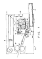
- Fig. 1 is a sectional view of a recording apparatus according to the preferred embodiment of the invention.
- a photoreceptor drum 1 is disposed substantially in the center of a housing H of the recording apparatus and rotatable in the direction indicated by arrow A.
- the photoreceptor drum 1 is formed of a photoconductive material, such as an organic photoconductor (OPC), and is surrounded by a charger 2, a laser device 3, a developing and cleaning device 4, a transfer roller 5, a discharge lamp 6, and a disordering device 7.
- OPC organic photoconductor
- the charger 2 which is situated above the photoreceptor drum 1, charges the surface of the drum 1 substantially uniformly to -500 to 800 V.
- the laser device 3 applies a laser beam 8 to the surface of the photoreceptor drum 1, in accordance with the image to be recorded, and thus forms the desired electrostatic image.
- the developing and cleaning device 4 is provided with a hopper 9 containing a so-called one-componet developing agent T capable of being frictionally charged.
- a developing roller 10 is disposed in the hopper 9, and transports the developing agent T to the position where it faces the photoreceptor drum 1, and after image transfer, returns developing agent T remaining on the surface of the drum 1 to the hopper 9.
- the developing roller 10 is composed of a metal shaft 10a, an elastic layer 10b surrounding the shaft 10a, and a conductive surface layer 10C formed on the surface of the layer 10b.
- the developing roller has elasticity as a whole.
- the elastic layer 10b is formed of polyurethane foam, for example, while the material constituting the conductive surface layer 10C is selected from among materials (listed later) suitable for friction charging the developing agent T and having the required elasticity and friction characteristics.
- the conductive surface layer 10C may be formed by applying, for example, a mixture of polyurethane resin and 10 to 30% by weight of conductive carbon to the elastic layer 10b.
- the electric resistance required for the layer 10c ranges from 102 to 109 ⁇ ⁇ cm.
- the developing roller 10 is in pressure-contact with an elastic blade 13 which serves to form the developing agent T as a thin layer on the surface of the roller 10.
- the blade 13 may be formed of phosphor bronze, polyurethane resin, or silicone resin.
- the developing agent T passing through the blade 13 is charged negatively or to the same polarity as the photoreceptor drum 1, thus forming one or two developing agent layers.
- the developing roller 10 is connected with a bias power source 14, and is connected electrically with a surface layer 11.
- a predetermined developing bias can be applied to the roller 10 at the time of development and cleaning.
- the transfer roller 5 which is situated substantially directly beneath the photoreceptor drum 1, faces the peripheral surface of the drum 1 across a paper transportation path 16.
- the roller 5 has the same construction as the developing roller 10, and the electric resistance of its conductive surface layer 1°C ranges from 105 to 1010 ⁇ ⁇ cm.
- the transfer roller 5 applies a voltage of 800 to 1,800 V to the back surface of a sheet of transfer paper conveyed thereto, causing a toner to be electrostatically attracted to the front surface of the paper, and a toner image to be transferred from the photoreceptor drum 1 to the paper.
- This contact-type transfer means ensures reliable image transfer even in conditions of high humidity, so that the residual developing agent can be reduced to lower the cleaning load. Also, paper dust from the transfer paper can be removed and prevented from getting mixed with the developing agent.
- the disordering device 7 is provided with a conductive elastic brush 18 whose tip end or the vicinity thereof is in sliding contact with the photoreceptor drum 1 as the drum rotates, and a voltage of 0 to 400 V is applied to the drum through the brush 18.
- a voltage of 0 to 400 V is applied to the drum through the brush 18.
- the disordering device 7 Since the disordering device 7 is located above the photoreceptor drum 1, the developing agent T adhering to the elastic brush 18 can be prevented from dropping and being scattered within the apparatus. Thus, even if the developing agent T drops onto the photoreceptor drum 1, it can be transported on the drum 1 to be recovered directly by means of the developing device 4.
- the photoreceptor drum 1 is underlain by a paper supplying unit 19 containing paper sheets 17 which are fed onto the paper transportation path 16 by means of a paper supplying roller 20 disposed above the paper supplying unit 19.
- the transportation path 16 is provided with a fixing device 21 for fixing the transferred toner image to a paper sheet 17.
- the photoreceptor drum 1 is rotated in the direction indicated by arrow A, and its peripheral surface is charged to about -500 to -800 V by means of the charger 2. Subsequently, the laser beam 8 from the laser device 3 is applied to the charged region, thereby forming an electrostatic latent image on the surface of the photoreceptor drum 1. Then, the latent image is transported to a cleaning position where it faces the developing and cleaning device 4.
- the developing agent (toner) T is supplied by means of the developing roller 10 arranged within the developing and cleaning device 4, is caused to adhere to the electrostatic latent image on the surface of the photoreceptor drum 1, the developing roller 10 being at this time, pressed against the drum 1, so that the drum undergoes elastic deformation.
- the roller 10 comes into contact with the drum 1 with a predetermined nip width, whereby the toner T is caused to adhere to the latent image, thereby forming a toner image.
- the toner T adheres to that portion of the photoreceptor drum 1 exposed to the laser beam 8, thus subjecting the latent image to the so-called reverse development.
- the average particle size of the toner T used may range from 8 to 15 ⁇ m.
- the toner T is charged to about -5 to -30° c/g by friction between the blade 23 and the surface layer 10c of the developing roller 10, and a voltage of about -200 to -450 V is applied to the roller 10.
- the developed toner image is then transported to a transfer region where it faces the transfer roller 5. Meanwhile, as the paper supplying roller 20 rotates, the paper sheet 17 is fed from the paper supplying unit 19 in synchronism with the rotation of the photoreceptor drum 1.
- the transfer roller 5 When the paper sheet 17 comes into contact with the transfer roller 5, its back surface is positively charged. Accordingly, the toner image on the surface of the photoreceptor drum 1 is electrostatically attracted and transferred to the sheet 17.
- a voltage of 1,000 to 2,000 V from a DC power source 23 is applied to the transfer roller 5 via its rotating shaft. This voltage is applied to the conductive surface layer 10c having a resistance of 105 to 109 ⁇ ⁇ cm through the conducting part.
- the surface of the transfer roller 5 should preferably be formed of a material which enjoys smoothness and low friction characteristic.
- conductive fluoropolymer or conductive polyester is used as the material of the conductive surface layer 10c, whose surface can be easily cleaned by means of a cleaning blade 22.
- the rubber hardness of the whole transfer roller 5 preferably ranges from 25 to 50, as measured according a method provided by the Japanese Industrial Standards. With use of such a soft material, the allowance for the force of pressure of the transfer roller 5 of the photoreceptor drum 1 is good enough for a satisfactory result.
- the hatched region represents the range of satisfactory transfer efficiency (operating environment) obtained with use of the transfer roller 5.
- the hatched region of Fig. 4 represents the range of satisfactory transfer efficiency (operating environment) obtained with use of a conventional transfer charger based on corona discharge.
- a transfer efficiency of 85% or more can be obtained at the relative humidity of 30 to 85% when the transfer roller 5 (Fig. 3) is used, while it can be obtained at the relative humidity of 30 to 50% according to the method using the transfer charger.
- the relative humidity even if a allowable level of a transfer efficiency is lowered to 60%, the relative humidity only spreads to 30 to 70%, indicating that the maximum tolerance of the relative humidity can be increased to 70% at the most.
- the recording apparatus can efficiently non-patterning the residual toner after the transfer throughout a wide range of environment. Since the transfer roller 5 is directly in contact with the paper sheet 17 during the transfer, moreover, paper dust sticking to the sheet 17 can be efficiently removed by attraction by means of the roller 5. Accordingly, very little extraneous matter remains on the photoreceptor drum 1 after the transfer.
- transfer errors can be prevented, and a distinct transfer image can be obtained without being affected by the size or quality of the sheet 17.
- the paper sheet 17 is delivered to the fixing device 21, whereupon the toner is fused and fixed to the sheet 17. Then, the sheet 17 is discharged.
- a residual toner image or a positive or negative residual electrostatic latent image barely remains on the surface of the photoreceptor drum 1.
- the negative latent image is first erased by means of the discharge lamp 6.
- the residual toner reaches the location of the disordering device 7 as the drum 1 rotates, whereupon it is rendered nonpatterned by the device 7.
- the elastic brush 18 is brought into contact with the photoreceptor drum 1, and the residual electrostatic latent image and toner image are disordered by means of mechanical and electrostatic forces, thereby creating an unreadable state.
- the friction charging polarity of the material of the elastic brush 18 is made identical with that of the toner, so that a repulsive force is produced in the toner.
- the residual toner on the photoreceptor drum 1 cannot be attracted to the brush 18, that is, the toner is prevented from accumulating on the brush.
- a conductive material is used for the elastic brush 18, a repulsive force is produced between the brush 18 and the toner by applying a potential of the same polarity as the toner or ground potential to the brush.
- the toner is prevented from accumulating on the brush 18.
- the residual toner on the photoreceptor drum 1 is disordered in this manner.
- the disordered residual toner scatters on the surface of the drum 1 and lightly adheres to the surface without being seized by the elastic brush 18.
- the disordering device 7 does not serve as a cleaning device, but has an only auxiliary function for cleaning.
- the toner particles scattered on the surface of the photoreceptor drum 1 are distributed in too small dots to form characters or an image.
- the disordered region of the photoreceptor drum 1 is then transported to a charging position where it faces the charger 2, and charged by corona discharge. After the charging, the drum 1 is exposed by means of the laser device 3 to form an electrostatic latent image thereon, which then reaches again the developing and cleaning position where it faces the developing and cleaning device 4.
- the residual toner is spread uniformly and thin enough both in an exposed portion, to which the toner is expected to adhere, and in a non-exposed portion, so that there is no possibility of irregular exposure.
- the residual potential after exposure is uniform, so that a uniform toner image can be obtained even in a second cycle of development.
- the developing roller 10 has a hardness of 30 to 70 (based on the JIS rubber hardness measurement method) and a low resistance of 102 to 108 ⁇ ⁇ cm. If a linear load of 20 to 150 g/cm is applied to the developing roller 10, and if the roller 10 is brought into sliding contact with the photoreceptor drum 1 at a peripheral speed 1.5 to 4 times as high as the peripheral speed of the drum 1, a contact width (nip width) of 1 to 4 mm is formed. When the residual toner and the toner T on the developing roller 10 are in sliding contact at the nip portion, a great frictional force is produced between them, whereby the cleaning capacity can be increased. If the developing agent is formed of the toner T only, reduction of image quality, such as streaks, cannot be caused.
- the force of attraction by the developing bias is greater than that of the photoreceptor drum 1, so that the toner T adhering to the drum 1 is attracted to the developing and cleaning device 4 and recovered.
- new toner particles from the developing roller 10 are caused to adhere to the exposed portion by supplying the roller 10 with the developing bias of a proper value intermediate between the residual potential of the exposed portion and the potential of the non-exposed portion.
- the residual toner on the non-exposed portion is attracted to the developing roller 10 and recovered.
- the residual toner is in a small quantity, and is scattered in small dots by the disordering device 7, so that it can be efficiently recovered by means of the disordering and charging device 2.
- one toner image can be obtained by repeatedly rotating the photoreceptor drum 1. After the developing and cleaning, the toner image is transferred to the paper sheet 17 at the position where it faces the transfer roller 5. Thereafter, the same processes of operation are repeated.
- the memory image which has conventionally been produced, can be eliminated, and defective cleaning can be prevented, despite the use of the photoreceptor drum 1 with a short diameter.
- 20,000 copies were taken using an image area of about 7% and size-A4 paper sheets, they all were able to enjoy satisfactory images without entailing defective cleaning.
- a bias voltage is applied to the disordering device 7, moreover, it can be adjusted so that the toner is effectively disordered, and the recovery of the toner is positively prevented.
- the disordering device 7 can be prevented from being contaminated.
- the toner adhering to the disordering device 7 can be forced out onto the surface of the photoreceptor drum 1 by applying a voltage of, for example, about 100 to 300 V to the elastic brush 18 during non-operation, that is, while the non-image region is passing the device 7.
- the discharged toner is transported to the developing and cleaning device 4 to be recovered thereby.
- a voltage of 0 to 100 V is applied to the developing roller 10 without operating the charger 2 in order to prevent the photoreceptor drum 1 from being charged.
- the toner can be prevented from accumulating in the disordering device 7 by an alternative method.
- a charging region for attracting the toner adhering to the device 7 is formed in the non-image region on the photoreceptor drum 1.
- the drum 1 is charged to the polarity opposite to that of the electrostatic latent image by means of the transfer roller 5. This can be easily done in a reverse development system.
- the cleanerless developing system according to the present invention produces a particularly good cleaning effect with use of a one-component developing agent. Referring to Figs. 5 and 6, this effect will be described.
- Fig. 5 is a schematic view for illustrating the cleaning effect of the residual toner on the photoreceptor drum obtained with use of a two-component magnetic brush.
- Fig. 6 is a schematic view for illustrating the cleaning effect of the residual toner on the photoreceptor drum obtained with use of the contact-type one-component system or the one-component developing and cleaning device according to the present invention.
- the developing agent is a two-component developing agent which is formed of a carrier 31 and a toner 32.
- the carrier 31 is composed of ferrite or iron oxide particles with a diameter of 80 to 150 ⁇ m.
- the carrier 31 is brought into sliding contact with residual toner particles 35 on a photoreceptor drum 34.
- the particles of the carrier 31 is much bigger than the toner particles whose diameter is about 10 ⁇ m.
- the carrier 31 cannot be easily brought into contact with the residual toner particles 35, that is, the probability of contact is low, so that the residual toner particles 35 cannot be mechanically swept away with high efficiency.
- the developing agent is composed of a toner 42 only, and contains no carrier. Therefore, the toner 42 on an elastic developing roller 43 is directly pressed against residual toner particles 45 on a photoreceptor drum 44 for sliding contact.
- the particles of the same size are in sliding contact with one another, so that the probability of contact between residual toners and developing toners is very high. Accordingly, the mechanical sweeping capability is high, so that a satisfactory cleaning effect can be obtained. Since the particles in sliding contact are as small as 10 ⁇ m in diameter, moreover, streaky image noises, which is frequently generated in the above tow component system, cannot be caused.
- the transfer roller 5 is used as the contact-type transfer means in the device according to the embodiment shown in Fig. 1, it may be replaced by a transfer belt.
- the conductive elastic roller is used as the transfer roller 5.
- an insulating elastic roller or a corona transfer means including a belt may be used for the purpose.
- a roller-shaped rotating brush of the same material as the elastic brush 18 of the disordering device 7 may alternatively be used as the transfer roller.
- the rotating brush is shaped like the transfer roller 5, and the same applied voltage and force of pressure are used.
- the toner adhering to the rotating brush can be removed by means of a rotating electrode to which is applied a voltage of the polarity opposite to that of the voltage applied to the brush.
- the recording apparatus employs the elastic developing member, which is pressed against the electrostatic latent image on the image carrying body for sliding contact with a relative speed difference.
- a great frictional force can be produced between the elastic developing member and the residual developing agent to improve the cleaning efficiency.
- the reverse development is used, and the image carrying body and the developing agent are charged to the same polarity, so that the adhesion of the developing agent to the image carrying body can be weakened, and the cleaning efficiency for the residual developing agent can be improved. Furthermore, the use of the contact-type transfer means results in an improvement in transfer efficiency.
Applications Claiming Priority (2)
| Application Number | Priority Date | Filing Date | Title |
|---|---|---|---|
| JP1138841A JP2598131B2 (ja) | 1989-05-31 | 1989-05-31 | 画像形成装置 |
| JP138841/89 | 1989-05-31 |
Publications (3)
| Publication Number | Publication Date |
|---|---|
| EP0400571A2 true EP0400571A2 (de) | 1990-12-05 |
| EP0400571A3 EP0400571A3 (de) | 1992-05-13 |
| EP0400571B1 EP0400571B1 (de) | 1994-10-19 |
Family
ID=15231447
Family Applications (1)
| Application Number | Title | Priority Date | Filing Date |
|---|---|---|---|
| EP90110147A Expired - Lifetime EP0400571B1 (de) | 1989-05-31 | 1990-05-29 | Aufzeichnungsgerät |
Country Status (4)
| Country | Link |
|---|---|
| US (1) | US5122838A (de) |
| EP (1) | EP0400571B1 (de) |
| JP (1) | JP2598131B2 (de) |
| DE (1) | DE69013399T2 (de) |
Cited By (2)
| Publication number | Priority date | Publication date | Assignee | Title |
|---|---|---|---|---|
| EP0778506A1 (de) * | 1995-12-05 | 1997-06-11 | Brother Kogyo Kabushiki Kaisha | Elektrophotographische Bilderzeugungsvorrichtung und Entwicklungsrolle hierfür |
| EP0791861A2 (de) * | 1996-02-20 | 1997-08-27 | Canon Kabushiki Kaisha | Bildherstellungsverfahren |
Families Citing this family (19)
| Publication number | Priority date | Publication date | Assignee | Title |
|---|---|---|---|---|
| JPH052327A (ja) * | 1991-06-24 | 1993-01-08 | Tokyo Electric Co Ltd | 現像同時クリーニング方式の画像形成装置 |
| JPH0750337B2 (ja) * | 1991-06-25 | 1995-05-31 | 村田機械株式会社 | クリーナレス画像形成方法 |
| JP2619154B2 (ja) * | 1991-06-28 | 1997-06-11 | 株式会社東芝 | 画像形成装置 |
| JPH0511600A (ja) * | 1991-07-06 | 1993-01-22 | Fujitsu Ltd | 一成分現像剤を使用する静電記録装置 |
| JPH0568952A (ja) * | 1991-09-11 | 1993-03-23 | U S Chem:Kk | 被洗浄物の洗浄方法及び装置 |
| JPH05232792A (ja) * | 1992-02-20 | 1993-09-10 | Canon Inc | 現像装置 |
| EP0613067B1 (de) * | 1993-02-26 | 1998-08-26 | Mita Industrial Co. Ltd. | Übertragungsvorrichtung in einem Bilderzeugungsgerät |
| JP3300245B2 (ja) * | 1997-02-19 | 2002-07-08 | シャープ株式会社 | 画像形成装置 |
| US6033057A (en) * | 1997-02-24 | 2000-03-07 | Brother Kogyo Kabushiki Kaisha | Image forming device including toner supply unit for supplying toner particles to electrode array |
| CA2383475C (en) | 1999-08-19 | 2006-03-21 | Katsuragawa Denki Kabushiki Kaisha | Developing device |
| JP2001056605A (ja) * | 1999-08-19 | 2001-02-27 | Katsuragawa Electric Co Ltd | 非磁性一成分現像装置 |
| JP2002040799A (ja) * | 2000-07-27 | 2002-02-06 | Ricoh Co Ltd | 現像ロール及びそれを有する現像装置 |
| JP2005173485A (ja) | 2003-12-15 | 2005-06-30 | Canon Inc | 現像装置、プロセスカートリッジ及び画像形成装置 |
| JP2005173484A (ja) | 2003-12-15 | 2005-06-30 | Canon Inc | 画像形成装置及びプロセスカートリッジ |
| JP4510493B2 (ja) | 2004-03-29 | 2010-07-21 | キヤノン株式会社 | 画像形成装置 |
| JP4785408B2 (ja) | 2005-04-18 | 2011-10-05 | キヤノン株式会社 | 現像装置、プロセスカートリッジ及び画像形成装置 |
| JP4785407B2 (ja) | 2005-04-18 | 2011-10-05 | キヤノン株式会社 | 現像装置、プロセスカートリッジ及び画像形成装置 |
| EP2908179B1 (de) | 2014-02-18 | 2020-08-12 | Canon Kabushiki Kaisha | Entwicklungsvorrichtung, Prozesskartusche und Bilderzeugungsvorrichtung |
| JP2021189333A (ja) | 2020-06-01 | 2021-12-13 | キヤノン株式会社 | 現像装置、カートリッジ及び画像形成装置 |
Citations (8)
| Publication number | Priority date | Publication date | Assignee | Title |
|---|---|---|---|---|
| DE3401940A1 (de) * | 1983-01-20 | 1984-07-26 | Tokyo Shibaura Denki K.K., Kawasaki | Bilderzeugungsgeraet |
| JPS6090357A (ja) * | 1983-10-24 | 1985-05-21 | Nippon Telegr & Teleph Corp <Ntt> | 記録方法および装置 |
| JPS62175780A (ja) * | 1986-01-30 | 1987-08-01 | Mita Ind Co Ltd | 非晶質シリコン感光体を用いた電子写真装置 |
| DE3706873A1 (de) * | 1986-03-04 | 1987-09-10 | Toshiba Kawasaki Kk | Abbildungsgeraet |
| JPS62223771A (ja) * | 1986-03-26 | 1987-10-01 | Toshiba Corp | 現像装置 |
| JPH01124881A (ja) * | 1987-11-09 | 1989-05-17 | Ricoh Co Ltd | 静電潜像用現像部材 |
| DE3837527A1 (de) * | 1987-11-02 | 1989-05-18 | Toshiba Kawasaki Kk | Bilderzeugungsvorrichtung |
| EP0387096A2 (de) * | 1989-03-10 | 1990-09-12 | Kabushiki Kaisha Toshiba | Bilderzeugungsverfahren |
Family Cites Families (13)
| Publication number | Priority date | Publication date | Assignee | Title |
|---|---|---|---|---|
| US364926A (en) * | 1887-06-14 | Setts | ||
| DE1803414A1 (de) * | 1967-10-16 | 1969-07-03 | Addressograph Multigraph | Photoelektrostatische Kopier-Maschine |
| US3649262A (en) * | 1968-12-31 | 1972-03-14 | Xerox Corp | Simultaneous development-cleaning of the same area of an electrostatographic image support surface |
| US3617123A (en) * | 1969-02-06 | 1971-11-02 | Xerox Corp | Xerographic cleaning apparatus |
| JPS5830585B2 (ja) * | 1973-04-30 | 1983-06-30 | 株式会社リコー | デンシシヤシンフクシヤキ ニ オケル カンコウタイ ノ クリ−ニングホウホウ |
| JPS5515176A (en) * | 1978-07-20 | 1980-02-02 | Ricoh Co Ltd | Electrophotographic copying method |
| US4396275A (en) * | 1980-05-14 | 1983-08-02 | Minolta Camera Kabushiki Kaisha | Toner image transfer type electrographic copying machine |
| US4609280A (en) * | 1983-10-31 | 1986-09-02 | International Business Machines Corporation | Xerographic apparatus and process with backside photoconductor imaging |
| JPH083678B2 (ja) * | 1986-08-11 | 1996-01-17 | 株式会社東芝 | 現像装置 |
| JPH0814736B2 (ja) * | 1987-03-30 | 1996-02-14 | 株式会社東芝 | 記録装置 |
| JP2637104B2 (ja) * | 1987-07-16 | 1997-08-06 | 株式会社東芝 | 画像形成装置 |
| US4800147A (en) * | 1987-08-03 | 1989-01-24 | Xerox Corporation | Xerographic process without conventional cleaner |
| US4967231A (en) * | 1987-12-29 | 1990-10-30 | Kabushiki Kaisha Toshiba | Apparatus for forming an electrophotographic latent image |
-
1989
- 1989-05-31 JP JP1138841A patent/JP2598131B2/ja not_active Expired - Lifetime
-
1990
- 1990-05-29 DE DE69013399T patent/DE69013399T2/de not_active Expired - Lifetime
- 1990-05-29 EP EP90110147A patent/EP0400571B1/de not_active Expired - Lifetime
- 1990-05-31 US US07/531,103 patent/US5122838A/en not_active Expired - Lifetime
Patent Citations (8)
| Publication number | Priority date | Publication date | Assignee | Title |
|---|---|---|---|---|
| DE3401940A1 (de) * | 1983-01-20 | 1984-07-26 | Tokyo Shibaura Denki K.K., Kawasaki | Bilderzeugungsgeraet |
| JPS6090357A (ja) * | 1983-10-24 | 1985-05-21 | Nippon Telegr & Teleph Corp <Ntt> | 記録方法および装置 |
| JPS62175780A (ja) * | 1986-01-30 | 1987-08-01 | Mita Ind Co Ltd | 非晶質シリコン感光体を用いた電子写真装置 |
| DE3706873A1 (de) * | 1986-03-04 | 1987-09-10 | Toshiba Kawasaki Kk | Abbildungsgeraet |
| JPS62223771A (ja) * | 1986-03-26 | 1987-10-01 | Toshiba Corp | 現像装置 |
| DE3837527A1 (de) * | 1987-11-02 | 1989-05-18 | Toshiba Kawasaki Kk | Bilderzeugungsvorrichtung |
| JPH01124881A (ja) * | 1987-11-09 | 1989-05-17 | Ricoh Co Ltd | 静電潜像用現像部材 |
| EP0387096A2 (de) * | 1989-03-10 | 1990-09-12 | Kabushiki Kaisha Toshiba | Bilderzeugungsverfahren |
Non-Patent Citations (4)
| Title |
|---|
| PATENT ABSTRACTS OF JAPAN vol. 12, no. 19 (P-657)[2866] 21 January 1988; & JP-A-62 175 780 ( MITA IND ) 1 August 1987 * |
| PATENT ABSTRACTS OF JAPAN vol. 12, no. 90 (P-679)[2937] 24 March 1988; & JP-A-62 223 771 ( TOSHIBA ) 1 October 1987 * |
| PATENT ABSTRACTS OF JAPAN vol. 13, no. 368 (P-919)[3716] 16 August 1989; & JP-A-01 124 881 ( RICOH ) 17 May 1989 * |
| PATENT ABSTRACTS OF JAPAN vol. 9, no. 236 (P-390)[1959] 21 September 1985; & JP-A-60 090 357 ( NIPPON DENSHIN DENWA KOSHA ) 21 May 1985 * |
Cited By (4)
| Publication number | Priority date | Publication date | Assignee | Title |
|---|---|---|---|---|
| EP0778506A1 (de) * | 1995-12-05 | 1997-06-11 | Brother Kogyo Kabushiki Kaisha | Elektrophotographische Bilderzeugungsvorrichtung und Entwicklungsrolle hierfür |
| US5867755A (en) * | 1995-12-05 | 1999-02-02 | Brother Kogyo Kabushiki Kaisha | Electrophotographic type image forming device and developing roller for use in the device |
| EP0791861A2 (de) * | 1996-02-20 | 1997-08-27 | Canon Kabushiki Kaisha | Bildherstellungsverfahren |
| EP0791861A3 (de) * | 1996-02-20 | 1999-12-01 | Canon Kabushiki Kaisha | Bildherstellungsverfahren |
Also Published As
| Publication number | Publication date |
|---|---|
| EP0400571B1 (de) | 1994-10-19 |
| DE69013399T2 (de) | 1995-04-20 |
| JPH034276A (ja) | 1991-01-10 |
| EP0400571A3 (de) | 1992-05-13 |
| JP2598131B2 (ja) | 1997-04-09 |
| US5122838A (en) | 1992-06-16 |
| DE69013399D1 (de) | 1994-11-24 |
Similar Documents
| Publication | Publication Date | Title |
|---|---|---|
| EP0400563B1 (de) | Aufzeichnungsgerät | |
| EP0400571B1 (de) | Aufzeichnungsgerät | |
| EP0732633A2 (de) | Gerät und Verfahren um ein Bild zu erzeugen | |
| CA1168300A (en) | Imaging surface discharge and cleaning apparatus for electrophotographic copier | |
| JP2633711B2 (ja) | 画像形成装置 | |
| US5610697A (en) | Electrophotographic apparatus capable of preventing image deterioration attributable to residual toner particles | |
| EP0400572B1 (de) | Aufzeichnungsgerät | |
| EP0354310A1 (de) | Verfahren und Vorrichtung zum elektrophotographischen Kopieren | |
| US7058335B2 (en) | Process cartridge and image forming apparatus with toner fed cleaning mode | |
| EP0572738A1 (de) | Aufladungsvorrichtung, Bilderzeugungsgerät und von dem Bilderzeugungsgerät abnehmbare Arbeitseinheit | |
| JPH09218626A (ja) | 画像形成装置 | |
| JPS63241587A (ja) | 記録装置 | |
| JPH112946A (ja) | 画像形成装置 | |
| US6430383B1 (en) | Image transferring device and image forming apparatus including the same | |
| JP2667560B2 (ja) | 画像形成装置 | |
| JP3563915B2 (ja) | 画像形成装置 | |
| JP2625593B2 (ja) | 画像形成装置 | |
| JP2598131C (de) | ||
| JP2962622B2 (ja) | 画像形成装置 | |
| JP3317510B2 (ja) | 画像形成装置 | |
| JPH1031360A (ja) | 画像形成装置 | |
| JPH0486883A (ja) | 画像形成装置 | |
| JP3223837B2 (ja) | 画像形成装置 | |
| JP2598132C (de) | ||
| JPH0486884A (ja) | 記録装置 |
Legal Events
| Date | Code | Title | Description |
|---|---|---|---|
| PUAI | Public reference made under article 153(3) epc to a published international application that has entered the european phase |
Free format text: ORIGINAL CODE: 0009012 |
|
| 17P | Request for examination filed |
Effective date: 19900626 |
|
| AK | Designated contracting states |
Kind code of ref document: A2 Designated state(s): DE FR GB |
|
| PUAL | Search report despatched |
Free format text: ORIGINAL CODE: 0009013 |
|
| AK | Designated contracting states |
Kind code of ref document: A3 Designated state(s): DE FR GB |
|
| 17Q | First examination report despatched |
Effective date: 19930521 |
|
| GRAA | (expected) grant |
Free format text: ORIGINAL CODE: 0009210 |
|
| AK | Designated contracting states |
Kind code of ref document: B1 Designated state(s): DE FR GB |
|
| REF | Corresponds to: |
Ref document number: 69013399 Country of ref document: DE Date of ref document: 19941124 |
|
| ET | Fr: translation filed | ||
| PLBE | No opposition filed within time limit |
Free format text: ORIGINAL CODE: 0009261 |
|
| STAA | Information on the status of an ep patent application or granted ep patent |
Free format text: STATUS: NO OPPOSITION FILED WITHIN TIME LIMIT |
|
| 26N | No opposition filed | ||
| REG | Reference to a national code |
Ref country code: GB Ref legal event code: 746 Effective date: 19981012 |
|
| REG | Reference to a national code |
Ref country code: FR Ref legal event code: D6 |
|
| REG | Reference to a national code |
Ref country code: GB Ref legal event code: IF02 |
|
| REG | Reference to a national code |
Ref country code: GB Ref legal event code: 732E |
|
| REG | Reference to a national code |
Ref country code: FR Ref legal event code: TQ |
|
| REG | Reference to a national code |
Ref country code: FR Ref legal event code: ST Effective date: 20090119 |
|
| PG25 | Lapsed in a contracting state [announced via postgrant information from national office to epo] |
Ref country code: FR Free format text: LAPSE BECAUSE OF NON-PAYMENT OF DUE FEES Effective date: 20080602 |
|
| REG | Reference to a national code |
Ref country code: FR Ref legal event code: D3 |
|
| PGFP | Annual fee paid to national office [announced via postgrant information from national office to epo] |
Ref country code: DE Payment date: 20090527 Year of fee payment: 20 |
|
| PGFP | Annual fee paid to national office [announced via postgrant information from national office to epo] |
Ref country code: GB Payment date: 20090527 Year of fee payment: 20 |
|
| REG | Reference to a national code |
Ref country code: FR Ref legal event code: ST Effective date: 20100129 |
|
| PG25 | Lapsed in a contracting state [announced via postgrant information from national office to epo] |
Ref country code: GB Free format text: LAPSE BECAUSE OF EXPIRATION OF PROTECTION Effective date: 20100528 |
|
| REG | Reference to a national code |
Ref country code: FR Ref legal event code: D3 Effective date: 20120823 |
|
| PGFP | Annual fee paid to national office [announced via postgrant information from national office to epo] |
Ref country code: FR Payment date: 20120814 Year of fee payment: 20 |
|
| PGRI | Patent reinstated in contracting state [announced from national office to epo] |
Ref country code: FR Effective date: 20120823 |
|
| PG25 | Lapsed in a contracting state [announced via postgrant information from national office to epo] |
Ref country code: DE Free format text: LAPSE BECAUSE OF EXPIRATION OF PROTECTION Effective date: 20100529 |