EP0400525A2 - Bilderzeugungsgerät - Google Patents
Bilderzeugungsgerät Download PDFInfo
- Publication number
- EP0400525A2 EP0400525A2 EP90110059A EP90110059A EP0400525A2 EP 0400525 A2 EP0400525 A2 EP 0400525A2 EP 90110059 A EP90110059 A EP 90110059A EP 90110059 A EP90110059 A EP 90110059A EP 0400525 A2 EP0400525 A2 EP 0400525A2
- Authority
- EP
- European Patent Office
- Prior art keywords
- paper
- image forming
- time
- registration
- document
- Prior art date
- Legal status (The legal status is an assumption and is not a legal conclusion. Google has not performed a legal analysis and makes no representation as to the accuracy of the status listed.)
- Granted
Links
Images



Classifications
-
- G—PHYSICS
- G03—PHOTOGRAPHY; CINEMATOGRAPHY; ANALOGOUS TECHNIQUES USING WAVES OTHER THAN OPTICAL WAVES; ELECTROGRAPHY; HOLOGRAPHY
- G03G—ELECTROGRAPHY; ELECTROPHOTOGRAPHY; MAGNETOGRAPHY
- G03G15/00—Apparatus for electrographic processes using a charge pattern
- G03G15/22—Apparatus for electrographic processes using a charge pattern involving the combination of more than one step according to groups G03G13/02 - G03G13/20
- G03G15/28—Apparatus for electrographic processes using a charge pattern involving the combination of more than one step according to groups G03G13/02 - G03G13/20 in which projection is obtained by line scanning
- G03G15/30—Apparatus for electrographic processes using a charge pattern involving the combination of more than one step according to groups G03G13/02 - G03G13/20 in which projection is obtained by line scanning in which projection is formed on a drum
- G03G15/305—Apparatus for electrographic processes using a charge pattern involving the combination of more than one step according to groups G03G13/02 - G03G13/20 in which projection is obtained by line scanning in which projection is formed on a drum with special means to synchronize the scanning optic to the operation of other parts of the machine, e.g. photoreceptor, copy paper
-
- G—PHYSICS
- G03—PHOTOGRAPHY; CINEMATOGRAPHY; ANALOGOUS TECHNIQUES USING WAVES OTHER THAN OPTICAL WAVES; ELECTROGRAPHY; HOLOGRAPHY
- G03G—ELECTROGRAPHY; ELECTROPHOTOGRAPHY; MAGNETOGRAPHY
- G03G15/00—Apparatus for electrographic processes using a charge pattern
- G03G15/65—Apparatus which relate to the handling of copy material
- G03G15/6555—Handling of sheet copy material taking place in a specific part of the copy material feeding path
- G03G15/6558—Feeding path after the copy sheet preparation and up to the transfer point, e.g. registering; Deskewing; Correct timing of sheet feeding to the transfer point
- G03G15/6561—Feeding path after the copy sheet preparation and up to the transfer point, e.g. registering; Deskewing; Correct timing of sheet feeding to the transfer point for sheet registration
- G03G15/6564—Feeding path after the copy sheet preparation and up to the transfer point, e.g. registering; Deskewing; Correct timing of sheet feeding to the transfer point for sheet registration with correct timing of sheet feeding
-
- G—PHYSICS
- G03—PHOTOGRAPHY; CINEMATOGRAPHY; ANALOGOUS TECHNIQUES USING WAVES OTHER THAN OPTICAL WAVES; ELECTROGRAPHY; HOLOGRAPHY
- G03G—ELECTROGRAPHY; ELECTROPHOTOGRAPHY; MAGNETOGRAPHY
- G03G2215/00—Apparatus for electrophotographic processes
- G03G2215/00362—Apparatus for electrophotographic processes relating to the copy medium handling
- G03G2215/00367—The feeding path segment where particular handling of the copy medium occurs, segments being adjacent and non-overlapping. Each segment is identified by the most downstream point in the segment, so that for instance the segment labelled "Fixing device" is referring to the path between the "Transfer device" and the "Fixing device"
- G03G2215/00405—Registration device
-
- G—PHYSICS
- G03—PHOTOGRAPHY; CINEMATOGRAPHY; ANALOGOUS TECHNIQUES USING WAVES OTHER THAN OPTICAL WAVES; ELECTROGRAPHY; HOLOGRAPHY
- G03G—ELECTROGRAPHY; ELECTROPHOTOGRAPHY; MAGNETOGRAPHY
- G03G2215/00—Apparatus for electrophotographic processes
- G03G2215/00362—Apparatus for electrophotographic processes relating to the copy medium handling
- G03G2215/00535—Stable handling of copy medium
- G03G2215/00556—Control of copy medium feeding
-
- G—PHYSICS
- G03—PHOTOGRAPHY; CINEMATOGRAPHY; ANALOGOUS TECHNIQUES USING WAVES OTHER THAN OPTICAL WAVES; ELECTROGRAPHY; HOLOGRAPHY
- G03G—ELECTROGRAPHY; ELECTROPHOTOGRAPHY; MAGNETOGRAPHY
- G03G2215/00—Apparatus for electrophotographic processes
- G03G2215/00362—Apparatus for electrophotographic processes relating to the copy medium handling
- G03G2215/00535—Stable handling of copy medium
- G03G2215/00603—Control of other part of the apparatus according to the state of copy medium feeding
Definitions
- the present invention relates to an image forming apparatus such as a copying apparatus or the like, and more particularly to an image forming apparatus having a plurality of image forming modes such as, in the copying apparatus, a normal copying mode, a margin shift copying mode, a variable magnification copying mode and the like.
- copy paper is successively fed from a copy paper housing unit at predetermined time intervals, and delivered to registration rollers disposed in the vicinity of a transfer unit for transferring a toner image formed on the surface of a photoreceptor to the copy paper.
- the registration rollers cause the paper to be once stopped. Thereafter, the paper is fed to the transfer unit at a predetermined timing in synchronism with the rotation of the toner image on the photoreceptor.
- the copying apparatus is apt to be made in a larger scale and to be operated at a higher speed, thereby lengthening the paper delivery passage from the paper housing unit to the registration rollers. Accordingly, when continuously carrying out a copying operation on a plurality of paper sheets, there are instances where a plurality of paper sheets are present in the delivery passage. Therefore, if the stop period of time during which each copy paper is being stopped by the registration rollers, is changed, this may cause paper sheets to come into collision with each other or to be jammed in the delivery passage. In this connection, the paper stop period of time cannot be changed as far as copy paper sheets are present in the delivery passage.
- paper feed means take out paper from a paper housing unit at predetermined time intervals determined according to the sizes of the paper.
- Registration means feed the paper to image forming means after the paper has been stopped for a predeter mined period of time. In such a paper feeding, the paper feed time intervals are equal to the predetermined time intervals mentioned above.
- the registration means maintain the predetermined paper stop time constant in any image forming mode or even though the image forming mode is changed. Accordingly, in a series of image forming operations, the time at which paper is fed to the image forming means remains unchanged. Change in the relationship between the time at which paper is fed to the image forming means and the drive starting time of document scanning means, is solely made by changing the drive starting time of a document scanning means.
- an electrophotographic copying apparatus is adapted to carry out a copying operation in a copying mode selected from a plurality of copying modes including a margin shift copying mode for providing a margin at a paper end, a normal copying mode for copying a document without such a margin provided, and the like.
- the margin shift copying mode it is required that the positional relationship between the image on a photoreceptor functioning as the image forming means and paper fed to this photoreceptor, is different from that in the normal copying mode.
- the present invention is so arranged as to advance or delay the drive starting time of the document scanning means as compared with that in the normal copying mode.
- the time at which the registration means feeds paper to the photoreceptor is the same as in the normal copying mode, as mentioned earlier. That is, only the drive starting time of the document scanning means undergoes a change.
- the stop time during which paper is being stopped by the registration means remains unchanged in any copying mode or even though the copying mode is changed. Accordingly, even though the copying mode is changed with paper being present in the paper delivery passage between the paper feed means and the registra tion means, there is no likelihood of paper collision and paper jam in the paper delivery passage. Thus, smooth change in image forming mode can be assured. This is particularly advantageous in image forming on a plurality of paper sheets at a high speed where a plurality of paper sheets are present in close vicinity to one another in the paper delivery passage.
- the copying operations in other modes than the margin shift copying mode conventionally made by changing the time at which paper is fed to the photoreceptor may be made by changing the drive starting time of the document scanning means, as done in the margin shift copying mode mentioned above.
- Fig. 2 is a schematic view illustrating the arrangement of portions of an electrophotographic copying apparatus relating to an image forming apparatus embodying the present invention.
- a document 2 is to be set on a transparent platen 1.
- a light source 3 for illuminating and scanning the document 2.
- the light source 3 is movable transversely in Fig. 2.
- a home switch 4 is adapted to be turned ON.
- the light source 3 starts moving from the home position in the direction shown by an arrow 3a and reaches a scan starting position where the light source 3 starts substantially illuminating the document 2, a timing switch is turned ON.
- By monitoring an output from the home switch 4 it is judged whether or not the light source 3 is located in the home position.
- By monitoring an output from the timing switch 5 there may be detected the time at which the light source 3 passes through the scan starting position.
- the light reflected from the surface of the document 2 is directed to a photoreceptor drum 10 by reflecting mirros 6, 7, 8.
- the photoreceptor drum 10 is exposed to the reflected light from the document 2 thus directed to the photoreceptor drum 10, so that an electrostatic latent image is formed on the surface of the photoreceptor drum 10.
- the electrostatic latent image thus formed is developed into a toner image by a developing device 11.
- the copying apparatus further includes three paper housing units 12, 13, 14. Disposed correspondingly to the respective paper housing units 12, 13, 14 are forward feeding rollers 15, 16, 17, paper feeding rollers 18, 19, 20, retard rollers 21, 22, 23 and paper detector switches 24, 25, 26. Each of the forward feeding rollers 15, 16, 17 takes out paper housed in each of the corresponding paper housing units 12, 13, 14 successively from the top of a paper pile. Each of the paper feeding rollers 18, 19, 20 delivers the paper taken out from each of the paper housing units 12, 13, 14 to a paper delivery passage 50.
- the retard rollers 21, 22, 23 respectively disposed corresponding to the paper feeding rollers 18, 19, 20 are rotated in a direction of rotation identical with that of the corresponding paper feeding rollers 18, 19, 20 (i.e., a direction of rotation for delivering paper in the direction opposite to the direction in which the paper is delivered by the paper feeding rollers 18, 19, 20), thereby preventing a plurality of paper sheets to be simultaneously fed.
- the retard rollers 21, 22, 23 are rotated with smaller torque than that with which the paper feeding rollers 18, 19, 20 are rotated.
- Each set of forward feeding roller, paper feeding roller and retard roller is simultaneously started or stopped operating by a paper feeding clutch (not shown), and is adapted to feed paper to the paper delivery passage at predetermined time intervals determined according to the size of paper.
- Paper taken out from each of the paper housing units 12, 13, 14 is detected by each of paper feeding switches 24, 25, 26. Further, the paper is delivered to the paper delivery passage 50 by each set of field rollers 27, 28, 29, and then guided to registration rollers 31 through loop rollers 30.
- a registration switch 32 is disposed in a paper delivery passage 51 between the loop rollers 30 and the registration rollers 31. This registration switch 32 is adapted to detect paper delivered toward the registration rollers 31.
- the registration rollers 31 are adapted to feed paper to the photoreceptor drum 10 at a predetermined timing.
- the loop rollers 30 advance paper even after the paper tip has come in contact with the registration rollers 31, thus causing the paper to be bent by a predetermined amount immediately before the registration rollers 31. When the paper is bent in this way, the paper tip may sufficiently come in contact with the registration rollers 31 to prevent the paper from being obliquely fed to the photoreceptor drum 10.
- the paper fed to the photoreceptor drum 10 by the registration rollers 31 sticks to the surface of the photoreceptor drum 10, so that the toner image on the surface of the photoreceptor drum 10 is transferred to the paper surface by a transferring corona discharger 33.
- the subsequent processings such as a fixing processing and the like do not relate directly to the present invention and are well known. Accord ingly, a further description of these subsequent processings will be omitted here.
- Fig. 3 is a block diagram of the arrangement of an electric circuit for operating the mechanism in Fig. 2.
- the electric circuit comprises a CPU 34 serving as a control center, a ROM 35 containing the operation program for the CPU 34, a RAM 36 for storing data and the like, and an I/O interface 37.
- the RAM 36 has a paper feeding clutch OFF timer area 361, a loop timer area 362, an optical motor ON timer area 363 and a registration clutch ON timer area 364, these areas being required when the RAM 36 serves as so-called software timers.
- Outputs from the home switch 4, the timing switch 5, the paper feeding switches 24, 25, 26 and the registration switch 32 are adapted to be supplied to the CPU 34 through the I/O interface 37.
- a control signal supplied from the CPU 34 is adapted to be supplied, through the I/O interface 37, to an optical motor 38, paper feeding clutches 39, 40, 41, a loop clutch 42 and a registration clutch 43.
- the optical motor 38 is disposed for moving the light source 3.
- the paper feeding clutches 39, 40, 41 are respectively disposed for respectively changing the operation/stop mode of the set of the forward feeding roller 15, the paper feeding roller 18 and the retard roller 21, the set of the forward feeding roller 16, the paper feeding roller 19 and the retard roller 22, and the set of the forward feeding roller 17, the paper feeding roller 20 and the retard roller 23.
- the loop clutch 42 is disposed for changing the operation/stop mode of the loop rollers 30.
- the registration clutch 43 is disposed for changing the operation/stop mode of the registration rollers 31.
- Fig. 1 is a view illustrating the relationship between the paper feeding operation of the registration rollers 31 and the operation of the light source 3.
- t1, t2, t3 and t4 in Fig. 1 respectively have the following meanings:
- the periods of time to be preset to carry out a good copying operation may be expressed, as follows, with the use of the times t1 to t4 above-mentioned, based on the time at which the registration switch 32 is turned ON.
- each of the set of the forward feeding roller 15, the paper feeding roller 18 and the retard roller 21, the set of the forward feeding roller 16, the paper feeding roller 19 and the retard roller 22, and the set of the forward feeding roller 17, the paper feeding roller 20 and the retard roller 23, takes out and feeds paper from each of the paper housing units 12, 13, 14 at predetermined time intervals determined according to the sizes of paper housed in each of the paper housing units 12, 13, 14. Further, the timing at which paper is taken out in a series of copying operations, is maintained constant in any of the copying modes.
- each set of forward feeding roller, paper feeding roller and regard roller is driven at predetermined time intervals, or such that, after a predetermined period of time has passed after the rear end of paper had been detected by each of the paper feeding switches 24, 25, 26, the next paper is taken out.
- the sizes of paper housed in each of the paper housing units 12, 13, 14 may be detected by the CPU 34 by detecting, for example, the type of each paper cassette (not shown).
- the CPU 34 is adapted to turn ON each of the paper feeding clutch 39, 40, 41 at predetermined time intervals according to the paper sizes thus detected.
- the time intervals at which paper is fed toward the photoreceptor drum 10 under control of the loop rollers 30, the registration rollers 31 and the like are not changed and always remain constant for all copying modes, as will be discussed later.
- Such constant time intervals are equal to the constant time intervals above-mentioned at which paper is taken out.
- the time at which paper is fed to the photoreceptor drum 10 in a series of copying operations is constant for all copying mode.
- the time at which paper is taken out from each of the paper housing units 12, 13, 14, and the time at which paper is fed to the photoreceptor drum 10 by the registration rollers 31, are constant regardless of the copying mode applied.
- the drive starting time of the light source 3 (the time at which the optical motor 38 is turned ON) varies with the copying mode applied.
- the relationship between the time at which paper is fed to the photoreceptor drum 10 and the drive starting time of the light source 3, varies with the copying mode applied. Accordingly, there may be produced copying results equivalent to those produced by the prior art in which the paper feed time varies with the copying mode applied.
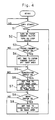
- Fig. 4 is a flow chart illustrating the control operation of the CPU 34. The following description will discuss the operation of the embodiment with reference to Fig. 4 and Figs. 1 to 3.
- step S1 When a copy start signal is given (step S1), the CPU 34 turns ON the paper feeding clutch 39, 40 or 41 corresponding to the paper housing unit selected from the three paper housing units 12, 13, 14 (step S2), thereby to start paper feeding.
- step S3 Upon detection of an ON signal of the paper feeding switch 24, 25 or 26 (step S3), the CPU 34 sets time to be preset to the paper feeding clutch OFF timer area 361 in the RAM 36 (step S4). Such time is equal to the sufficient and required period of time during which paper is delivered to the paper delivery passage 50 after it has been taken out from the paper housing unit 12, 13 or 14 and detected by the paper feeding switch 24, 25 or 26.
- step S5 When it is detected that the registration switch 32 is turned ON (step S5), the CPU 34 sets a predetermined time to the loop timer area 362 in the RAM 36 (step S6), and also sets another predetermined time to the optical motor ON timer area 363 (step S7).
- time of (t4 + ⁇ ) is set to the loop timer area 362 regardless of the copy mode applied.
- Set to the optical motor ON timer area 363 is time of (t1 + t2) - (t3 + t4 + ⁇ ) for the normal copying mode, time of (t1 + t2) - (t3 + t4 + ⁇ + ⁇ ) for the margin shift copying mode, or time of ⁇ (t1 + ⁇ ) + t2 ⁇ - (t3 + t4 + ⁇ ) for the variable magnification copying mode.
- the time at which the loop clutch 43 is turned ON is maintained constant, while the time at which the optical motor 38 is turned ON, varies with the copying mode applied.
- step S8 When it is detected that the timing switch 5 is turned ON (step S8), the CPU 34 sets a predetermined time to the registration clutch ON timer area 364 (step S9).
- Such set time is equal to the time of (t2 - t3) for the normal copying mode, ⁇ t2 - (t3 + ⁇ ) ⁇ ; for the margin shift copying mode, or (t2 - t3) for the variable magnification copying mode.
- the time at which paper is fed to the transfer position B may be fine-adjusted, so that the toner image on the surface of the photoreceptor drum 10 is securely synchronized with paper according to the copying mode applied.
- the period of time from the time at which the registration switch 32 has been turned ON, to the time at which the registration clutch 43 is turned ON may be calculated as set forth below:
- the period of time from the time at which the registration switch 32 has been turned ON, to the time at which the registration clutch 43 is turned ON is constant regardless of the copying mode applied.
- paper is taken out from the paper housing unit 12, 13 or 14 at predetermined time intervals regardless of the copying mode applied.
- the time intervals at which the registration switch 32 is turned ON are apparently equal to the predetermined time intervals mentioned above.
- the time intervals at which the registration rollers 31 feed paper to the photoreceptor drum 10 are also equal to the predetermined time intervals above-mentioned.
- the time at which paper is taken out from the paper housing unit 12, 13 or 14, and the time at which the registration rollers 31 feed paper to the photoreceptor drum 10 are constant regardless of the copying mode applied.
- the paper stop period of time during which paper is being stopped by the registration rollers 31, is substantially equal to ⁇ and constant.
- the control may be preferably carried out based on the time at which the timing switch 5 is turned ON, as done in the foregoing.
- the CPU 34 may carry out operations shown in Figs. 5, 6, 7 and 8 when, for example, an interrupting operation or the like is required.
- the following description will discuss such operations.
- Fig. 5 shows a control opertion of the CPU 34 in connection with the paper feeding clutches 39, 40, 41.
- step S41 When the time preset to the paper feeding clutch OFF timer area 361 is not equal to "0" (step S41), the CPU 34 carries out a decrement of such time (step S42). When the remaining time becomes “0" (step S43), the CPU 34 turns OFF the paper feeding clutch 39, 40 or 41 which has been turned ON at the step S2 (step S44).
- Fig. 6 shows a control operation of the CPU 34 in connection with the loop clutch 42.
- step S61 When the time preset to the loop timer area 362 is not equal to "0" (step S61), the CPU 34 carries out a decrement of such time (step S62). When the remaining time becomes “0" (step S63), the CPU 34 turns OFF the loop clutch 42 which has been turned ON at the step S2 (step S64).
- Fig. 7 shows a control operation of the CPU 34 in connection with the optical motor 38.
- the CPU 34 carries out a decrement of such time (step S72).
- the CPU 34 starts the optical motor 38 (step S74). Accordingly, the optical motor 38 is turned ON after the time stored in the optical motor ON timer area 363 has passed after the registration switch 32 had been turned ON.
- Fig. 8 shows a control operation of the CPU 34 in connection with the registration clutch 43.
- the CPU 34 carries out a decrement of such time (step S82).
- the CPU 34 turns ON the registration clutch 43 and the loop clutch 42, thereby to start paper feed from the registration rollers 31 toward the photoreceptor drum 10 (step S84). This adjusts, in a fine manner, the timing at which paper if fed from the registration rollers 31 to the transfer position B .
- both the time at which paper is taken out from the paper housing unit 12, 13 or 14, and the time at which the registration rollers 31 feed paper to the photoreceptor drum 10, are constant regardless of the copying mode applied.
- the period of time during which paper is being stopped by the registration rollers 31 as above-mentioned is substantially constant regardless of the copying mode applied. Accordingly, even though the copying mode is changed with paper being present in the paper delivery passage 50, there is no likelihood of paper collision and paper jam therein. This ensures a smooth change in copying mode.
- the present invention is not limited to the embodiment above-mentioned.
- the times to be respectively set to the loop timer area 362, the optical motor ON timer area 363 and the registration clutch ON timer area 364 are set based on the time at which the registration switch 32 is turned ON. Alternately, such times may be set based on the time at which the paper feeding switch 24, 25 or 26 is turned ON.
- the light source 3 is adapted to scan the document 2. Alternately, a photo sensor-array faced on the document can be used for scanning the document and reading the image thereof. A variety of other modifications may be made without departing from the scope of the present invention.
Landscapes
- Physics & Mathematics (AREA)
- General Physics & Mathematics (AREA)
- Control Or Security For Electrophotography (AREA)
- Registering Or Overturning Sheets (AREA)
- Paper Feeding For Electrophotography (AREA)
Applications Claiming Priority (2)
| Application Number | Priority Date | Filing Date | Title |
|---|---|---|---|
| JP1137168A JPH031167A (ja) | 1989-05-29 | 1989-05-29 | 画像形成装置 |
| JP137168/89 | 1989-05-29 |
Publications (3)
| Publication Number | Publication Date |
|---|---|
| EP0400525A2 true EP0400525A2 (de) | 1990-12-05 |
| EP0400525A3 EP0400525A3 (de) | 1991-05-22 |
| EP0400525B1 EP0400525B1 (de) | 1994-08-03 |
Family
ID=15192410
Family Applications (1)
| Application Number | Title | Priority Date | Filing Date |
|---|---|---|---|
| EP90110059A Expired - Lifetime EP0400525B1 (de) | 1989-05-29 | 1990-05-28 | Bilderzeugungsgerät |
Country Status (4)
| Country | Link |
|---|---|
| US (1) | US5073802A (de) |
| EP (1) | EP0400525B1 (de) |
| JP (1) | JPH031167A (de) |
| DE (1) | DE69011214T2 (de) |
Cited By (4)
| Publication number | Priority date | Publication date | Assignee | Title |
|---|---|---|---|---|
| EP0551862A3 (en) * | 1992-01-13 | 1993-10-27 | Canon Kk | Image forming system with original feeding apparatus |
| EP0675415A3 (de) * | 1994-03-28 | 1996-07-10 | Xerox Corp | Bedrucken von Laschen mit einem Drucker. |
| WO1998018051A1 (de) * | 1996-10-22 | 1998-04-30 | OCé PRINTING SYSTEMS GMBH | Verfahren und einrichtung zum steuern der abgabe von blättern aus eingabefächern einer papierabgabevorrichtung einer druck- und kopiereinrichtung |
| EP1386865A3 (de) * | 2002-07-29 | 2005-07-20 | Eastman Kodak Company | Verfahren und Vorrichtung zur Bereitstellung von Bögen in einer Druckmaschine |
Families Citing this family (8)
| Publication number | Priority date | Publication date | Assignee | Title |
|---|---|---|---|---|
| US5278623A (en) * | 1989-06-21 | 1994-01-11 | Konica Corporation | Image forming apparatus |
| US5328164A (en) * | 1990-12-14 | 1994-07-12 | Fuji Photo Film Co., Ltd. | Sheet feeding device |
| JP3610076B2 (ja) * | 1991-12-10 | 2005-01-12 | キヤノン株式会社 | 記録装置 |
| JPH06102727A (ja) * | 1992-09-21 | 1994-04-15 | Konica Corp | 複写機 |
| US5384632A (en) * | 1992-09-30 | 1995-01-24 | Minolta Camera Kabushiki Kaisha | Digital copier enabling setting of a plurality of copying conditions in a single setting operation before copying is initiated |
| JPH06239489A (ja) * | 1993-02-19 | 1994-08-30 | Fuji Xerox Co Ltd | 転写材搬送装置 |
| JP3299585B2 (ja) * | 1993-03-29 | 2002-07-08 | 株式会社東芝 | 給紙装置 |
| JP6056325B2 (ja) * | 2012-09-26 | 2017-01-11 | ブラザー工業株式会社 | 画像形成装置 |
Family Cites Families (15)
| Publication number | Priority date | Publication date | Assignee | Title |
|---|---|---|---|---|
| JPS5911905B2 (ja) * | 1975-12-18 | 1984-03-19 | キヤノン株式会社 | カヘンバイフクシヤキ |
| JPS5865456A (ja) * | 1981-10-14 | 1983-04-19 | Minolta Camera Co Ltd | 可変倍転写型複写機 |
| US4497569A (en) * | 1982-09-21 | 1985-02-05 | Xerox Corporation | Copy processing system for a reproduction machine |
| JPS59162569A (ja) * | 1983-03-08 | 1984-09-13 | Canon Inc | 画像形成装置 |
| JPS59223636A (ja) * | 1983-05-30 | 1984-12-15 | Konishiroku Photo Ind Co Ltd | 複写装置 |
| JPS6048834A (ja) * | 1983-08-29 | 1985-03-16 | Minolta Camera Co Ltd | 機械装置の制御装置 |
| JPS6048835A (ja) * | 1983-08-29 | 1985-03-16 | Minolta Camera Co Ltd | 機械装置の制御装置 |
| DE3612349A1 (de) * | 1985-04-16 | 1986-10-16 | Sharp K.K., Osaka | Kopiergeraet |
| JP2575626B2 (ja) * | 1985-08-08 | 1997-01-29 | キヤノン株式会社 | 画像形成装置の制御装置 |
| JPS62129869A (ja) * | 1985-11-30 | 1987-06-12 | Mita Ind Co Ltd | 複写機 |
| US4819029A (en) * | 1986-01-29 | 1989-04-04 | Minolta Camera Kabushiki Kaisha | Copying machine capable of producing a copy with a filing margin |
| US4739376A (en) * | 1986-02-10 | 1988-04-19 | Ricoh Company, Ltd. | Copying machine |
| JPS6323170A (ja) * | 1986-07-01 | 1988-01-30 | Minolta Camera Co Ltd | 複写機 |
| JPS63180634A (ja) * | 1987-01-20 | 1988-07-25 | Konica Corp | 給紙装置 |
| JP2668886B2 (ja) * | 1987-08-31 | 1997-10-27 | ミノルタ株式会社 | 複写機 |
-
1989
- 1989-05-29 JP JP1137168A patent/JPH031167A/ja active Pending
-
1990
- 1990-05-21 US US07/525,669 patent/US5073802A/en not_active Expired - Fee Related
- 1990-05-28 EP EP90110059A patent/EP0400525B1/de not_active Expired - Lifetime
- 1990-05-28 DE DE69011214T patent/DE69011214T2/de not_active Expired - Fee Related
Cited By (6)
| Publication number | Priority date | Publication date | Assignee | Title |
|---|---|---|---|---|
| EP0551862A3 (en) * | 1992-01-13 | 1993-10-27 | Canon Kk | Image forming system with original feeding apparatus |
| US5579083A (en) * | 1992-01-13 | 1996-11-26 | Canon Kabushiki Kaisha | Image forming system with original feeding apparatus |
| EP0675415A3 (de) * | 1994-03-28 | 1996-07-10 | Xerox Corp | Bedrucken von Laschen mit einem Drucker. |
| WO1998018051A1 (de) * | 1996-10-22 | 1998-04-30 | OCé PRINTING SYSTEMS GMBH | Verfahren und einrichtung zum steuern der abgabe von blättern aus eingabefächern einer papierabgabevorrichtung einer druck- und kopiereinrichtung |
| US6179281B1 (en) | 1996-10-22 | 2001-01-30 | Oc{acute over (e)} Printing Systems GmbH | Method and device to control ejection of sheets from input compartments in a paper output device belonging to a printing and photocopying system |
| EP1386865A3 (de) * | 2002-07-29 | 2005-07-20 | Eastman Kodak Company | Verfahren und Vorrichtung zur Bereitstellung von Bögen in einer Druckmaschine |
Also Published As
| Publication number | Publication date |
|---|---|
| JPH031167A (ja) | 1991-01-07 |
| DE69011214D1 (de) | 1994-09-08 |
| EP0400525B1 (de) | 1994-08-03 |
| US5073802A (en) | 1991-12-17 |
| DE69011214T2 (de) | 1995-04-20 |
| EP0400525A3 (de) | 1991-05-22 |
Similar Documents
| Publication | Publication Date | Title |
|---|---|---|
| EP0333107B1 (de) | Original-Zuführvorrichtung | |
| US20010033050A1 (en) | Image formation apparatus | |
| EP0400525A2 (de) | Bilderzeugungsgerät | |
| JPH09130549A (ja) | デジタル画像形成装置 | |
| JPH11109828A (ja) | 電子写真装置 | |
| US5103267A (en) | Image forming system for performing simplex and duplex recording | |
| EP0987606B1 (de) | Bilderzeugungsgerät und Verfahren | |
| JPH08238819A (ja) | 画像出力装置の手差サイズ検出システム | |
| US5081490A (en) | Method of controlling image forming apparatus when a jam occurs in the original feeder | |
| US5826135A (en) | Paper feeding control method of an image forming apparatus | |
| US5210583A (en) | Electrophotographic printer which positions the leading edge of a recording sheet | |
| JP2001331074A (ja) | 画像形成装置及び画像形成方法 | |
| JPH11157150A (ja) | 画像形成装置 | |
| US4611903A (en) | Image forming apparatus with reduced image forming time | |
| JP2003327345A (ja) | 画像形成装置および画像形成制御方法 | |
| JP2915925B2 (ja) | 画像形成装置の制御方法 | |
| JP2524762B2 (ja) | 電子写真複写装置及び制御方法 | |
| JP2637408B2 (ja) | 画像形成装置 | |
| JPS6247253A (ja) | 画像形成装置 | |
| JP2001072268A (ja) | 給紙装置 | |
| JP3702670B2 (ja) | 画像形成装置、画像形成装置の書き込み方法、画像形成方法及び画像形成装置の制御方法 | |
| JPH07209937A (ja) | 画像形成装置 | |
| JPH1124525A (ja) | 画像記録装置、画像読取装置並びに画像形成装置 | |
| JP3507789B2 (ja) | 画像形成装置 | |
| JPH09230711A (ja) | 画像形成装置 |
Legal Events
| Date | Code | Title | Description |
|---|---|---|---|
| PUAI | Public reference made under article 153(3) epc to a published international application that has entered the european phase |
Free format text: ORIGINAL CODE: 0009012 |
|
| AK | Designated contracting states |
Kind code of ref document: A2 Designated state(s): DE FR GB NL |
|
| 17P | Request for examination filed |
Effective date: 19901219 |
|
| PUAL | Search report despatched |
Free format text: ORIGINAL CODE: 0009013 |
|
| AK | Designated contracting states |
Kind code of ref document: A3 Designated state(s): DE FR GB NL |
|
| 17Q | First examination report despatched |
Effective date: 19920821 |
|
| GRAA | (expected) grant |
Free format text: ORIGINAL CODE: 0009210 |
|
| AK | Designated contracting states |
Kind code of ref document: B1 Designated state(s): DE FR GB NL |
|
| ET | Fr: translation filed | ||
| REF | Corresponds to: |
Ref document number: 69011214 Country of ref document: DE Date of ref document: 19940908 |
|
| PLBE | No opposition filed within time limit |
Free format text: ORIGINAL CODE: 0009261 |
|
| STAA | Information on the status of an ep patent application or granted ep patent |
Free format text: STATUS: NO OPPOSITION FILED WITHIN TIME LIMIT |
|
| 26N | No opposition filed | ||
| PGFP | Annual fee paid to national office [announced via postgrant information from national office to epo] |
Ref country code: FR Payment date: 19980511 Year of fee payment: 9 |
|
| PGFP | Annual fee paid to national office [announced via postgrant information from national office to epo] |
Ref country code: NL Payment date: 19980531 Year of fee payment: 9 |
|
| PGFP | Annual fee paid to national office [announced via postgrant information from national office to epo] |
Ref country code: GB Payment date: 19990526 Year of fee payment: 10 |
|
| PGFP | Annual fee paid to national office [announced via postgrant information from national office to epo] |
Ref country code: DE Payment date: 19990528 Year of fee payment: 10 |
|
| PG25 | Lapsed in a contracting state [announced via postgrant information from national office to epo] |
Ref country code: NL Free format text: LAPSE BECAUSE OF NON-PAYMENT OF DUE FEES Effective date: 19991201 |
|
| PG25 | Lapsed in a contracting state [announced via postgrant information from national office to epo] |
Ref country code: FR Free format text: LAPSE BECAUSE OF NON-PAYMENT OF DUE FEES Effective date: 20000131 |
|
| NLV4 | Nl: lapsed or anulled due to non-payment of the annual fee |
Effective date: 19991201 |
|
| REG | Reference to a national code |
Ref country code: FR Ref legal event code: ST |
|
| PG25 | Lapsed in a contracting state [announced via postgrant information from national office to epo] |
Ref country code: GB Free format text: LAPSE BECAUSE OF NON-PAYMENT OF DUE FEES Effective date: 20000528 |
|
| GBPC | Gb: european patent ceased through non-payment of renewal fee |
Effective date: 20000528 |
|
| PG25 | Lapsed in a contracting state [announced via postgrant information from national office to epo] |
Ref country code: DE Free format text: LAPSE BECAUSE OF NON-PAYMENT OF DUE FEES Effective date: 20010301 |