EP0387197B1 - Nachladbare Farbbandkassette - Google Patents
Nachladbare Farbbandkassette Download PDFInfo
- Publication number
- EP0387197B1 EP0387197B1 EP90810154A EP90810154A EP0387197B1 EP 0387197 B1 EP0387197 B1 EP 0387197B1 EP 90810154 A EP90810154 A EP 90810154A EP 90810154 A EP90810154 A EP 90810154A EP 0387197 B1 EP0387197 B1 EP 0387197B1
- Authority
- EP
- European Patent Office
- Prior art keywords
- carrier
- housing
- ribbon
- core
- centring
- Prior art date
- Legal status (The legal status is an assumption and is not a legal conclusion. Google has not performed a legal analysis and makes no representation as to the accuracy of the status listed.)
- Expired - Lifetime
Links
- 238000000034 method Methods 0.000 claims description 2
- 238000004804 winding Methods 0.000 description 16
- 239000000463 material Substances 0.000 description 4
- 210000000078 claw Anatomy 0.000 description 3
- 238000003780 insertion Methods 0.000 description 2
- 230000037431 insertion Effects 0.000 description 2
- 125000006850 spacer group Chemical group 0.000 description 2
- 230000000903 blocking effect Effects 0.000 description 1
- 230000007613 environmental effect Effects 0.000 description 1
- 238000001746 injection moulding Methods 0.000 description 1
- 238000004519 manufacturing process Methods 0.000 description 1
- 239000002184 metal Substances 0.000 description 1
- 210000000056 organ Anatomy 0.000 description 1
- 238000004806 packaging method and process Methods 0.000 description 1
- 238000003825 pressing Methods 0.000 description 1
- 239000000243 solution Substances 0.000 description 1
- 238000009987 spinning Methods 0.000 description 1
Images


Classifications
-
- B—PERFORMING OPERATIONS; TRANSPORTING
- B41—PRINTING; LINING MACHINES; TYPEWRITERS; STAMPS
- B41J—TYPEWRITERS; SELECTIVE PRINTING MECHANISMS, i.e. MECHANISMS PRINTING OTHERWISE THAN FROM A FORME; CORRECTION OF TYPOGRAPHICAL ERRORS
- B41J35/00—Other apparatus or arrangements associated with, or incorporated in, ink-ribbon mechanisms
- B41J35/28—Detachable carriers or holders for ink-ribbon mechanisms
-
- B—PERFORMING OPERATIONS; TRANSPORTING
- B41—PRINTING; LINING MACHINES; TYPEWRITERS; STAMPS
- B41J—TYPEWRITERS; SELECTIVE PRINTING MECHANISMS, i.e. MECHANISMS PRINTING OTHERWISE THAN FROM A FORME; CORRECTION OF TYPOGRAPHICAL ERRORS
- B41J32/00—Ink-ribbon cartridges
-
- B—PERFORMING OPERATIONS; TRANSPORTING
- B41—PRINTING; LINING MACHINES; TYPEWRITERS; STAMPS
- B41J—TYPEWRITERS; SELECTIVE PRINTING MECHANISMS, i.e. MECHANISMS PRINTING OTHERWISE THAN FROM A FORME; CORRECTION OF TYPOGRAPHICAL ERRORS
- B41J33/00—Apparatus or arrangements for feeding ink ribbons or like character-size impression-transfer material
- B41J33/14—Ribbon-feed devices or mechanisms
- B41J33/24—Ribbon-feed devices or mechanisms with drive applied directly to ribbon
- B41J33/26—Ribbon-feed devices or mechanisms with drive applied directly to ribbon by rollers engaging the ribbon
Definitions
- a reloadable ribbon cassette is known from DE-OS 35 24 730. It is a cassette with a hinged lid.
- An unwinder with an unwinder core is contained in the cassette housing.
- the unwinding core is seated on a sleeve of a rotatable brake disc.
- a belt tensioning device interacts with the brake disc.
- the tape is guided from the unwinding reel via the tape tensioning device and tape guide members at the free ends of two protruding legs of the housing to a winding core.
- This is rotatably mounted on a spring-loaded swivel arm.
- the swivel arm presses the winding core against a spiked wheel mounted on the housing with a drive pin for engaging a drive element of the typewriter.
- the cassette is first removed from the typewriter.
- the swivel arm with the take-up spool is swiveled away from the sprocket by means of a lever. Now the full take-up reel with the take-up core and the empty take-up core can be removed.
- the new supply reel is placed on the brake disc and a new take-up core on the swivel arm attached.
- the beginning of the tape can then be threaded over the tape guide elements.
- a pin with a predetermined breaking point is attached to the beginning of the tape. The lower part of the pin is finally inserted into a slot in the winding core and the rest of the pin is broken off.
- the reloaded cassette After closing the lid, the reloaded cassette can be reinserted into the typewriter.
- the reloading process described is cumbersome and complicated, so that it sometimes fails.
- the cartridge must be removed from the typewriter for reloading.
- the lever is locked and the associated pivoting movement of the winding core against the sprocket wheel, the tape becomes loose, so that the first windings of the winding spool are poorly wound. This can lead to problems with further winding.
- the object of the present invention is to design a reloadable ink ribbon cassette in accordance with the preamble of claim 1 such that the above disadvantages are avoided. This object is achieved by the characterizing features of claim 1.
- the reloading unit according to the invention is defined in claim 5.
- the reloading unit 20 can be used as a whole as a conventional ribbon cartridge in a typewriter. In contrast to conventional cartridges, it consists of an adapter 1 and a reloading unit 20.
- the adapter 1 is designed such that it can remain permanently in the typewriter, while the reloading unit 20 is replaced as a disposable item after the ink ribbon has been used up.
- the essential mechanical parts required for the belt drive and the belt tension are accommodated in the adapter 1.
- the reloading unit 20 contains only a minimum of individual parts. This training achieves an ecologically and economically optimal solution in that the reloading unit is inexpensive to manufacture and its disposal does little for the environment burdened because it contains no metal parts and can be made from environmentally friendly, disposable materials with little material.
- the adapter 1 is shown in Figures 2 and 3. It consists of an open-top housing 13 made of plastic injection molding with a flat base plate 13c and a side wall 13b. The rearmost area of the housing 13 is covered with a narrow cover 14.
- the housing 13 has two protruding legs 13a.
- a centering pin 7 projects from the base plate 13c at each of its free ends.
- Another centering pin 8 is arranged in the attachment end of the right leg 13a.
- a plurality of spacer webs 10 for supporting the reloading unit 20 and two hollow mandrels 3, 4 are integrally formed on the base plate 13c.
- a brake disc 11 with an integrally formed coaxial sleeve 11a is rotatably and captively attached to the mandrel 3.
- the sleeve 11a has a plurality of drivers 11b on its outer circumference.
- the brake disc 11 is toothed on its outer circumference.
- a clamping element 12 designed as a double-armed lever is pivotably mounted on a housing-fixed pin 12a adjacent to a corner of the housing 13.
- the first arm of the element 12 has latches 19 at the free end, which are pressed by a spring 15 for engagement in the toothing of the brake disc 11.
- the other arm of the element 12 carries a belt tensioning roller 54 at the free end.
- a nose 18 is formed on the first arm. Adjacent to the right rear corner of the housing 13, a drive pin 55 is rotatably mounted in the housing 13 with, for example, a cruciform through opening for the engagement of a drive shaft of the typewriter.
- An arm 2 is pivotable on the pin 55. This carries a drive wheel 53 designed as a spiked wheel, which is non-rotatably connected to the drive pin 55 via toothed intermediate wheels 56.
- the arm 2 has a finger 17 which interacts with the nose 18.
- the arm 2 is prestressed by a spring 16, so that during operation the drive wheel 53 is pressed against a take-up spool 43a placed on the mandrel 4.
- the arm 2 has a control cam 52.
- a double-armed, double-cranked actuating lever 6 is snapped with a cylindrical middle part into a bearing 5 formed on the side wall 13b.
- a lever arm 51 of the lever 6 runs on the control cam 52 and pivots the arm 2 against the force of the spring 16 into the loading position shown in FIG. 2.
- the lever arm 51 engages in a notch 52a of the control cam 52.
- the finger 17 pivots the element 12 clockwise over the nose 18, so that the tensioning roller 54 is pivoted away from its operating position in the direction of arrow B.
- the latches 19 also disengage from the toothing of the brake disk 11.
- the reloading unit 20 comprises a thin-walled carrier 21 injection-molded from plastic with two projecting carrier legs 21a and a circumferential side wall 21b.
- the side wall 21b is interrupted at the free leg ends and at the right rear edge of the carrier 21.
- Hollow pins 27 are formed on the free leg ends as band guide members. At the top, the hollow pins 27 carry a retaining collar 27b for the ink ribbon 42.
- Two further ribbon guide members 28 are arranged adjacent to two hollow pins 23, 24.
- the hollow pins 23, 24 each have two latching lugs 25 at their free ends.
- An unwinding core 41 with an unwinding spool 40 is attached to the hollow pin 23 and held captively by the lugs 25.
- a winding core 43 is attached to the other hollow pin 24.
- the ink ribbon 42 is guided from the unwind spool 40 via the ribbon guide members 27, 28 to the winding core 43 and fastened thereon.
- On the left carrier leg 21a there is an opening 30 through which the tensioning roller 54 projects during operation.
- Another opening 31 on the right rear edge of the carrier 21 serves for the entry of the arm 2 with the drive wheel 53.
- an elongated hole is recessed as a locking recess 29 for engaging the locking lugs 9.
- Grip tabs 33 are formed on the side wall 21b adjacent to the free leg ends, so that the recharging unit 20 can be easily removed from the adapter 1.
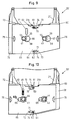
- the carrier 21 with the unwinding spool 40 and the winding core 43 is inserted into a cardboard box 34 (FIGS. 4 and 5).
- the side wall 21b of the carrier 21 has two guide elements 32 on each side.
- the box 34 can be separated into a first part 35a and a second part 35b by a circumferential tear tape 36.
- the first part 35a encloses the area of the carrier 21 with the unwinding spool 40 and the winding core 43. It has two circular cutouts 39 on the top through which the winding core 43 and the unwinding core 41 are inserted. Both cores 41, 43 engage behind the cutouts 39 with locking lugs 44 (FIG. 8).
- the part 35a On the underside, the part 35a has round openings 39a coaxial with the cutouts 39 for inserting the sleeves 11a and the mandrel 4. At the rear right edge, a piece 37 can be separated from the part 35a by a perforation to expose the opening 31. Radially to the unwinding core 41 an elongated hole 46 extends on the upper side of part 35a as a tape supply indicator. The second part 35b encloses the two legs 21a. This part 35b is removed before use. A cardboard plate 38 is fastened to the inner surface of its upper side as a transport lock.
- the free end of the plate 38 is inserted between the take-up spool 40 and the upper side of the part 35a, so that the unwinding spool 40 is locked without play between the underside of the part 35a and the plate 38.
- the plate 38 covers the longitudinal slot 46 and is removed together with the part 35b before use. This makes the game necessary for free spinning the unwind spool 40.
- a pawl 26 is formed on the hollow pin 23, which engages in driving claws 41a of the unwinding core 41 and prevents the unwinding spool 40 from rotating counterclockwise.
- the actuating lever 6 is pivoted into the loading position according to FIG. 2 with the adapter inserted in the typewriter and the used reloading unit 20 is removed.
- the tear tape 36 is torn off and the part 35b with the plate 38 is removed.
- the piece 37 is cut off.
- the rear side of the part 35a is inserted under the cover 14 and the hollow pin 27, 28 is placed on the centering pins 7, 8.
- the locking recesses 29 snap into the locking lugs 9 by pressing on the grip tabs 33.
- the band tensioning element 12 is pivoted such that the band tensioning roller 54 in the illustration according to FIG.
- the drive pin 55 is gradually rotated by the typewriter after each stop. This rotation is transmitted via the intermediate wheels 56 to the drive wheel 53, which thus rotates the take-up spool 43a in the counterclockwise direction and pulls the ink ribbon 42 off via the ribbon guide members 27, 28.
- a force acts on the band tensioning roller 54, which swivels the band tensioning element 12 clockwise until the latches 19 disengage from the toothing of the brake disc 11 and thus the unwinding spool 40 can rotate one tooth further.
- a constant, elastic band tension is maintained by the spring 15 and the band tensioning element 12.
- the described design of the cassette enables simple reloading analogous to the replacement of conventional cassettes, the adapter 1 being able to remain permanently in the typewriter. No cumbersome threading of the new ribbon is required.
- the ribbon is tensioned after insertion so that the take-up spool is tightly wound from the start. This can prevent operational disruptions will.
- the carrier 21 and the cores 41, 43 can be made very light and made of the same material as the ink ribbon. As a result, the cost of materials and the environmental impact are low, especially when this consumable is recycled.
- the cardboard box 34 serves both as transport packaging and as a cover during operation.
- the embodiment according to FIGS. 9 and 10 of the reloading unit 20 ' is designed for use in the same adapter 1 according to FIGS. 2 and 3.
- the casing 60 differs from the box part 53a according to FIGS.
- the transport lock is fundamentally different from the embodiment according to FIGS. 4 to 8.
- the slider 65 has approximately the same width as the sleeve 60, but is somewhat shorter than that. It has two keyhole-like slots 66, 67 through which the Lugs 44 of the cores 41, 43 protrude.
- the holes 66, 67 have two circular segment-shaped edge sections 68, 69.
- the section 68 has a diameter which is larger than the outside diameter of the locking lugs 44.
- the diameter of the section 69 is somewhat smaller than the diameter of the cutouts 39 according to FIGS. 4 and 8.
- the front and rear of the slide 65 each have a cutout 70, 71 with an outer edge 73 parallel to the longitudinal edges 72 of the slide 65.
- a detent 74 projects from the edge 73.
- the edge 73 is encompassed by the hook-shaped springs 61, 62.
- the slide 65 additionally has two grip notches 75, 76, by means of which it can be moved from the locked position shown in FIG. 9 into the release position according to FIG. 10.
- the slider 65 In both positions, the slider 65 is secured behind the detents 74 by latching the detent springs 61, 62.
- the locked position (FIG. 9)
- the cores 41, 43 are clamped through the sections 69 of the holes 66, 67 and thus secured against rotation.
- the axial play between the spool 40 and the upper box wall is canceled in an analogous manner, as shown in FIG. 8, except that the upper box wall lies directly on the spool body here.
- the release position In the release position (FIG. 10) the clamping of the cores 41, 43 is released and the upper box wall lifts off the coil body.
- a longitudinal slot 77 of the slide 65 is aligned with the elongated hole 46 in the box 60, so that the tape supply indicator is visible.
- the top of the box can be used to visually lift the locking position from the release position be colored green on the right edge 78, red on the left edge 79, or the edges 78, 79 can be labeled accordingly.
- the hole 66 expediently has a projection 69a on its edge section 69, which engages in the locked position in the core 41 and additionally secures the unwinding spool 40.
- the embodiment according to FIGS. 9 and 10 has the advantage over that according to FIGS. 4 to 8 that the unwinding spool is secured until after insertion.
- the reloading unit 20 ' can also be removed from the adapter 1 in between, before the end of the tape supply on the spool 40, and replaced by another reloading unit 20' with a different tape quality. This is desirable, for example, if alternately document-correct (uncorrectable) fonts are to be written on the same typewriter and correctable ribbons are to be used.
- the slide 65 is first pushed into the blocking position (FIG. 9) and then the exchange unit 20' is removed from the adapter 1. The winding and unwinding spools are then secured against twisting during handling.
- FIG. 11 schematically shows a variant in which the adapter 1 according to FIG. 2 forms part of a typewriter 85.
- the two housing legs 13a then protrude on both sides of the character printing device, for example one Type wheel 86, against the platen roller 87 in front.
- the centering pins 7 are immediately adjacent to the platen roller 87.
- the housing 13 is expediently pivoted in the typewriter 85 about an axis 88 parallel to the platen roller 87, so that during operation the ink ribbon 42 stretched between the ribbon guide members 27, which is between the platen roller 87 and the type wheel 86 is carried out, can be pivoted between a raised writing position and a lowered reading position. 11, parts that are not mentioned here are omitted from the typewriter 85 for better clarity.
- FIGS. 12 to 14 show a further embodiment of the invention, the same reference numerals being used for analog parts as in the embodiment according to FIGS. 1 to 8, so that a detailed description of these parts is unnecessary.
- the embodiment according to FIGS. 12 to 14 differs from that according to FIGS. 1 to 8 essentially only by the type of centering of the legs 21a '' of the carrier 21 '' on the legs 13a 'of the adapter 1' and by the function of the Belt guide elements 27 ''.
- the adapter 1 'and reloading unit 20'' are constructed in the same way as in the embodiment according to FIGS. 1 to 8, so that the parts which are not connected to the belt guide and centering are omitted or only indicated schematically in a simplified manner.
- the centering members 7 'of the housing legs 13a' are here semi-cylindrical bolts 90 projecting perpendicularly from the housing legs 13a ', which are closed at the top by a flange 91 projecting in the direction of the free leg ends.
- the centering elements 27b ′′ are designed as semi-cylindrical shells 92 adjacent to the free end of the carrier legs 21a ′′. Starting from the shells 92, the carrier legs 21a ′′ each have an elongated hole 93 through which the relevant bolt 90 can be inserted.
- the band guide member 27 ′′ is formed by an end edge 94 of an extension 95 of the side wall 21b ′′ of the carrier 21 ′′.
- the band 42 is drawn in dashed lines.
- the front edge 94 is delimited at the top by a projection 96 so that the band 42 cannot slip upwards.
- the embodiment according to FIG. 12 is suitable for use in a typewriter which, in operation, has machine-side tape guiding elements 97, which are shown schematically in FIGS. 13 and 14 adjacent to the platen roller 87 '.
- the outside distance of the two band guide members 97 is slightly less than the inside distance of the extensions 95 from one another.
- the band 42 is first inserted between the organs 97 and the platen roller 87 'by means of the extensions 95 and the carrier legs 21a ′′ with their elongated holes 93 onto the bolts 90 plugged on, the reloading unit 20 ′′ being inclined to the adapter 1 ′ (arrow A in FIG. 13).
- the reloading unit is pulled back in the direction of arrow B until the shells 92 engage positively around the bolts 90.
- the adapter 20 ′′ is pivoted in the direction of arrow C, so that the unwinding core 41 ′′ is pushed onto the sleeve 11a ′′.
- the typewriter is ready for operation (Fig. 14).
- the relatively soft support legs 21a ′′ are in turn precisely centered by the rigid bolts 90.
- the flanges 91 overlap the shells 92 so that the reloading unit 20 ′′ is held securely on the adapter 1 ′.
- the type of centering shown on the basis of the embodiment according to FIGS. 12 to 14 can also be used in typewriters which have no machine-side tape guide members 97.
- the elongated holes 93 can be made correspondingly shorter.
Landscapes
- Impression-Transfer Materials And Handling Thereof (AREA)
Priority Applications (1)
| Application Number | Priority Date | Filing Date | Title |
|---|---|---|---|
| AT90810154T ATE91974T1 (de) | 1989-03-08 | 1990-03-01 | Nachladbare farbbandkassette. |
Applications Claiming Priority (4)
| Application Number | Priority Date | Filing Date | Title |
|---|---|---|---|
| CH86389 | 1989-03-08 | ||
| CH863/89 | 1989-03-08 | ||
| DE8908696U DE8908696U1 (de) | 1989-07-18 | 1989-07-18 | Nachladbare Farbbandkassette |
| DE8908696U | 1989-07-18 |
Publications (2)
| Publication Number | Publication Date |
|---|---|
| EP0387197A1 EP0387197A1 (de) | 1990-09-12 |
| EP0387197B1 true EP0387197B1 (de) | 1993-07-28 |
Family
ID=25685936
Family Applications (1)
| Application Number | Title | Priority Date | Filing Date |
|---|---|---|---|
| EP90810154A Expired - Lifetime EP0387197B1 (de) | 1989-03-08 | 1990-03-01 | Nachladbare Farbbandkassette |
Country Status (4)
| Country | Link |
|---|---|
| US (1) | US5127750A (es) |
| EP (1) | EP0387197B1 (es) |
| DE (1) | DE59002056D1 (es) |
| ES (1) | ES2042261T3 (es) |
Families Citing this family (11)
| Publication number | Priority date | Publication date | Assignee | Title |
|---|---|---|---|---|
| US5383733A (en) * | 1992-07-24 | 1995-01-24 | Summagraphics Corporation | Ribbon cassette for a printer |
| WO1994022673A1 (en) * | 1993-04-06 | 1994-10-13 | Ayres David W | Disposable ribbon cassette within a reloadable cartridge |
| US5286122A (en) * | 1993-05-25 | 1994-02-15 | Datasouth Computer Corporation | Ribbon cartridge with take-up arm |
| US5415485A (en) * | 1994-08-11 | 1995-05-16 | Marenger; Michael L. | Ribbon cartridge reloader |
| JPH09240090A (ja) * | 1996-03-12 | 1997-09-16 | Brother Ind Ltd | 印字装置、記録装置及びリボンカセット |
| EP1036663B1 (de) * | 1999-03-17 | 2009-10-21 | Frama AG | Farbbandkassette |
| FR2796372B1 (fr) * | 1999-07-13 | 2001-09-07 | Dassault Automatismes | Cassette a ruban consommable, notamment pour dispositif de traitement de titres de transport |
| US6910819B2 (en) * | 2003-08-12 | 2005-06-28 | Brady Worldwide, Inc. | Printer cartridge |
| FR2877878A1 (fr) * | 2004-11-16 | 2006-05-19 | Sagem | Consommable pour dispositif d'impression avec support en u et receptacle adapte a ce consommable |
| DE102006036716B3 (de) * | 2006-06-02 | 2007-09-27 | Artech Gmbh Design + Production In Plastic | Vorrichtung und Verfahren zur Umrüstung eines Druckers |
| JP4650523B2 (ja) * | 2008-06-18 | 2011-03-16 | カシオ電子工業株式会社 | 電子装置、消耗品カートリッジ、交換部品、及び利用度合を報知する方法 |
Family Cites Families (20)
| Publication number | Priority date | Publication date | Assignee | Title |
|---|---|---|---|---|
| US3976183A (en) * | 1975-02-18 | 1976-08-24 | Standard Manifold Company | Typewriter ribbon supply adapter for replaceable ribbons |
| GB1535396A (en) * | 1976-05-21 | 1978-12-13 | Grafton & Son Walter | Support means for cassettes or cartridges for inked or filmed ribbons |
| US4212551A (en) * | 1977-11-17 | 1980-07-15 | Litton Business Systems, Inc. | Ribbon cartridge |
| US4240757A (en) * | 1978-12-26 | 1980-12-23 | Centronics Data Computer Corp. | Fanfold replacement ribbon package |
| US4367963A (en) * | 1980-07-21 | 1983-01-11 | Wordex | Refillable typewriter ribbon cartridge |
| JPS6310305Y2 (es) * | 1980-12-11 | 1988-03-28 | ||
| US4486107A (en) * | 1982-09-24 | 1984-12-04 | Willcox Frederick P | Ribbon guiding and directing structure and cartridge |
| DE3418545A1 (de) * | 1984-05-18 | 1985-11-21 | Olympia Werke Ag, 2940 Wilhelmshaven | Farbbandkassette fuer schreib- oder aehnliche bueromaschinen |
| JPS6119383A (ja) * | 1984-07-06 | 1986-01-28 | Ricoh Co Ltd | 印字装置のリボンカ−トリツジ |
| JPS61160276A (ja) * | 1984-12-31 | 1986-07-19 | Canon Inc | インクリボンカセツト |
| DE8633789U1 (de) * | 1986-12-18 | 1987-03-05 | TA Triumph-Adler AG, 8500 Nürnberg | Farbbandkassette für Schreib- oder ähnliche Maschinen |
| DE3705058A1 (de) * | 1987-02-18 | 1988-09-01 | Olympia Aeg | Farbbandkassette mit nachladbaren farbbandspulen |
| EP0279243B1 (de) * | 1987-02-18 | 1992-08-19 | AEG Olympia Office GmbH | Farbbandkassette mit nachbladbaren Farbbandspulen |
| DE3742860A1 (de) * | 1987-02-18 | 1988-09-01 | Olympia Aeg | Farbbandkassette mit nachladbaren farbbandspulen |
| DE3722224A1 (de) * | 1987-07-04 | 1989-01-12 | Olympia Aeg | Farbbandkassette fuer schreib- oder aehnliche bueromaschinen |
| DE3741360A1 (de) * | 1987-12-07 | 1989-06-15 | Triumph Adler Ag | Aufnahmevorrichtung fuer einen traeger eines farbbandes in schreib- oder aehnlichen maschinen |
| DE3741361A1 (de) * | 1987-12-07 | 1989-06-15 | Triumph Adler Ag | Traeger eines farbbandes fuer schreib- und aehnliche maschinen |
| DE3741363A1 (de) * | 1987-12-07 | 1989-06-15 | Triumph Adler Ag | Traeger eines farbbandes fuer schreib- und aehnliche maschinen |
| CH678037A5 (es) * | 1987-12-22 | 1991-07-31 | Olympia Aeg | |
| KR930007622B1 (ko) * | 1988-11-29 | 1993-08-14 | 가부시기가이샤 도시바 | 통전전사 프린터 |
-
1990
- 1990-03-01 ES ES199090810154T patent/ES2042261T3/es not_active Expired - Lifetime
- 1990-03-01 DE DE9090810154T patent/DE59002056D1/de not_active Expired - Fee Related
- 1990-03-01 EP EP90810154A patent/EP0387197B1/de not_active Expired - Lifetime
- 1990-03-08 US US07/491,476 patent/US5127750A/en not_active Expired - Lifetime
Also Published As
| Publication number | Publication date |
|---|---|
| ES2042261T3 (es) | 1993-12-01 |
| EP0387197A1 (de) | 1990-09-12 |
| US5127750A (en) | 1992-07-07 |
| DE59002056D1 (de) | 1993-09-02 |
Similar Documents
| Publication | Publication Date | Title |
|---|---|---|
| DE10229009B4 (de) | Abdeckfilm-Übertragungsgerät und Verfahren zum Austauschen von Abdeckfilm-Übertragungsbändern | |
| DE69031873T2 (de) | Bandvorratskassette für Thermodruckapparat | |
| DE2321651A1 (de) | Auswechselbare farbbandkassette fuer schreibmaschinen oder dergleichen | |
| EP0214379B1 (de) | Austauscheinrichtung für eine nachladbare Kassette einer Schreibmaschine o.dgl. | |
| EP0387197B1 (de) | Nachladbare Farbbandkassette | |
| DE2810768A1 (de) | Antriebsvorrichtung fuer das farbband von schreib-, daten- oder aehnlichen maschinen | |
| DE2950270A1 (de) | Farbbandkassette mit integrierter spulensperre | |
| EP0033532B1 (de) | Farbbandkassette für eine Schreib- oder ähnliche Büromaschine | |
| EP0279242B1 (de) | Austauscheinheit für eine Farbbandkassette | |
| DE69532141T2 (de) | Bandkassette für ein Übertragungswerkzeug für Beschichtungsfilm und ein Übertragungswerkzeug für Beschichtungsfilm | |
| DE69130367T2 (de) | Transferdrucker | |
| DE69120744T2 (de) | Kassette für mittels Übertragung arbeitenden Aufzeichnungsträger und Aufzeichnungsvorrichtung | |
| EP0279243B1 (de) | Farbbandkassette mit nachbladbaren Farbbandspulen | |
| DE8908696U1 (de) | Nachladbare Farbbandkassette | |
| DE3524057A1 (de) | Farbbandkassette fuer eine schreib- oder bueromaschine aehnlicher bauart | |
| DE3625089C2 (es) | ||
| DE60005658T2 (de) | Medienführungsglied | |
| DE3741360C2 (es) | ||
| DE2547957B2 (de) | Löschvorrichtung für kraftangetriebene Schreib- o.a. Büromaschinen | |
| DE2429703C3 (de) | Farbbandautomat mit einer taschenförmigen Kassette für Schreib- oder ähnliche Maschinen | |
| DE3927421A1 (de) | Farbbandkassette fuer eine aufnahmevorrichtung einer schreib- oder aehnlichen bueromaschine | |
| DE3705056A1 (de) | Farbbandkassette mit nachladbaren farbbandspulen | |
| DE3919119A1 (de) | Farbbandkassette mit auswechselbaren farbbandspulen fuer schreib- oder bueromaschinen aehnlicher bauart | |
| DE2106630A1 (de) | Kassette fur streifenförmiges Material | |
| DE3737657A1 (de) | Nachladbare farbbandkassette fuer schreib- oder bueromaschinen aehnlicher bauart |
Legal Events
| Date | Code | Title | Description |
|---|---|---|---|
| PUAI | Public reference made under article 153(3) epc to a published international application that has entered the european phase |
Free format text: ORIGINAL CODE: 0009012 |
|
| AK | Designated contracting states |
Kind code of ref document: A1 Designated state(s): AT BE CH DE DK ES FR GB GR IT LI LU NL SE |
|
| 17P | Request for examination filed |
Effective date: 19900820 |
|
| 17Q | First examination report despatched |
Effective date: 19920402 |
|
| GRAA | (expected) grant |
Free format text: ORIGINAL CODE: 0009210 |
|
| ITF | It: translation for a ep patent filed | ||
| AK | Designated contracting states |
Kind code of ref document: B1 Designated state(s): AT BE CH DE DK ES FR GB GR IT LI LU NL SE |
|
| PG25 | Lapsed in a contracting state [announced via postgrant information from national office to epo] |
Ref country code: GR Free format text: LAPSE BECAUSE OF FAILURE TO SUBMIT A TRANSLATION OF THE DESCRIPTION OR TO PAY THE FEE WITHIN THE PRESCRIBED TIME-LIMIT Effective date: 19930728 |
|
| REF | Corresponds to: |
Ref document number: 91974 Country of ref document: AT Date of ref document: 19930815 Kind code of ref document: T |
|
| GBT | Gb: translation of ep patent filed (gb section 77(6)(a)/1977) |
Effective date: 19930728 |
|
| REF | Corresponds to: |
Ref document number: 59002056 Country of ref document: DE Date of ref document: 19930902 |
|
| ET | Fr: translation filed | ||
| REG | Reference to a national code |
Ref country code: ES Ref legal event code: FG2A Ref document number: 2042261 Country of ref document: ES Kind code of ref document: T3 |
|
| PG25 | Lapsed in a contracting state [announced via postgrant information from national office to epo] |
Ref country code: DK Effective date: 19940301 Ref country code: AT Effective date: 19940301 |
|
| PG25 | Lapsed in a contracting state [announced via postgrant information from national office to epo] |
Ref country code: SE Free format text: LAPSE BECAUSE OF NON-PAYMENT OF DUE FEES Effective date: 19940302 Ref country code: ES Free format text: LAPSE BECAUSE OF NON-PAYMENT OF DUE FEES Effective date: 19940302 |
|
| PG25 | Lapsed in a contracting state [announced via postgrant information from national office to epo] |
Ref country code: LU Free format text: LAPSE BECAUSE OF NON-PAYMENT OF DUE FEES Effective date: 19940331 Ref country code: BE Effective date: 19940331 |
|
| PLBE | No opposition filed within time limit |
Free format text: ORIGINAL CODE: 0009261 |
|
| STAA | Information on the status of an ep patent application or granted ep patent |
Free format text: STATUS: NO OPPOSITION FILED WITHIN TIME LIMIT |
|
| 26N | No opposition filed | ||
| BERE | Be: lapsed |
Owner name: FRANZ BUTTNER A.G. Effective date: 19940331 |
|
| PGFP | Annual fee paid to national office [announced via postgrant information from national office to epo] |
Ref country code: CH Payment date: 19940930 Year of fee payment: 5 |
|
| PG25 | Lapsed in a contracting state [announced via postgrant information from national office to epo] |
Ref country code: NL Effective date: 19941001 |
|
| NLV4 | Nl: lapsed or anulled due to non-payment of the annual fee | ||
| EUG | Se: european patent has lapsed |
Ref document number: 90810154.6 Effective date: 19941010 |
|
| PG25 | Lapsed in a contracting state [announced via postgrant information from national office to epo] |
Ref country code: LI Effective date: 19950331 Ref country code: CH Effective date: 19950331 |
|
| REG | Reference to a national code |
Ref country code: CH Ref legal event code: PL |
|
| REG | Reference to a national code |
Ref country code: ES Ref legal event code: FD2A Effective date: 19990405 |
|
| PGFP | Annual fee paid to national office [announced via postgrant information from national office to epo] |
Ref country code: FR Payment date: 20010208 Year of fee payment: 12 |
|
| PGFP | Annual fee paid to national office [announced via postgrant information from national office to epo] |
Ref country code: GB Payment date: 20010219 Year of fee payment: 12 |
|
| PGFP | Annual fee paid to national office [announced via postgrant information from national office to epo] |
Ref country code: DE Payment date: 20010222 Year of fee payment: 12 |
|
| REG | Reference to a national code |
Ref country code: GB Ref legal event code: IF02 |
|
| PG25 | Lapsed in a contracting state [announced via postgrant information from national office to epo] |
Ref country code: GB Free format text: LAPSE BECAUSE OF NON-PAYMENT OF DUE FEES Effective date: 20020301 |
|
| PG25 | Lapsed in a contracting state [announced via postgrant information from national office to epo] |
Ref country code: DE Free format text: LAPSE BECAUSE OF NON-PAYMENT OF DUE FEES Effective date: 20021001 |
|
| GBPC | Gb: european patent ceased through non-payment of renewal fee |
Effective date: 20020301 |
|
| PG25 | Lapsed in a contracting state [announced via postgrant information from national office to epo] |
Ref country code: FR Free format text: LAPSE BECAUSE OF NON-PAYMENT OF DUE FEES Effective date: 20021129 |
|
| REG | Reference to a national code |
Ref country code: FR Ref legal event code: ST |
|
| PG25 | Lapsed in a contracting state [announced via postgrant information from national office to epo] |
Ref country code: IT Free format text: LAPSE BECAUSE OF NON-PAYMENT OF DUE FEES;WARNING: LAPSES OF ITALIAN PATENTS WITH EFFECTIVE DATE BEFORE 2007 MAY HAVE OCCURRED AT ANY TIME BEFORE 2007. THE CORRECT EFFECTIVE DATE MAY BE DIFFERENT FROM THE ONE RECORDED. Effective date: 20050301 |