EP0374599B1 - Verfahren zur Herstellung mehrlagiger verstreckter Bändchen - Google Patents
Verfahren zur Herstellung mehrlagiger verstreckter Bändchen Download PDFInfo
- Publication number
- EP0374599B1 EP0374599B1 EP89122562A EP89122562A EP0374599B1 EP 0374599 B1 EP0374599 B1 EP 0374599B1 EP 89122562 A EP89122562 A EP 89122562A EP 89122562 A EP89122562 A EP 89122562A EP 0374599 B1 EP0374599 B1 EP 0374599B1
- Authority
- EP
- European Patent Office
- Prior art keywords
- tapes
- folded
- folding
- webs
- manufacturing
- Prior art date
- Legal status (The legal status is an assumption and is not a legal conclusion. Google has not performed a legal analysis and makes no representation as to the accuracy of the status listed.)
- Expired - Lifetime
Links
- 238000004519 manufacturing process Methods 0.000 title claims abstract description 10
- 238000000034 method Methods 0.000 title claims abstract description 6
- 239000004744 fabric Substances 0.000 claims abstract description 6
- 239000012815 thermoplastic material Substances 0.000 claims abstract description 4
- 238000004804 winding Methods 0.000 claims abstract 3
- 239000004743 Polypropylene Substances 0.000 claims description 5
- -1 polypropylene Polymers 0.000 claims description 5
- 229920001155 polypropylene Polymers 0.000 claims description 5
- 239000000463 material Substances 0.000 claims description 2
- 239000000203 mixture Substances 0.000 claims description 2
- 239000004033 plastic Substances 0.000 claims description 2
- 238000009941 weaving Methods 0.000 abstract 1
- 238000009998 heat setting Methods 0.000 description 3
- 239000010410 layer Substances 0.000 description 3
- 206010040954 Skin wrinkling Diseases 0.000 description 2
- 230000003247 decreasing effect Effects 0.000 description 2
- 239000011888 foil Substances 0.000 description 2
- 230000002093 peripheral effect Effects 0.000 description 2
- 125000004805 propylene group Chemical class [H]C([H])([H])C([H])([*:1])C([H])([H])[*:2] 0.000 description 2
- 230000015572 biosynthetic process Effects 0.000 description 1
- 239000003292 glue Substances 0.000 description 1
- 230000007935 neutral effect Effects 0.000 description 1
- QQONPFPTGQHPMA-UHFFFAOYSA-N propylene Natural products CC=C QQONPFPTGQHPMA-UHFFFAOYSA-N 0.000 description 1
- 239000002356 single layer Substances 0.000 description 1
- 229920001169 thermoplastic Polymers 0.000 description 1
- 239000004416 thermosoftening plastic Substances 0.000 description 1
Images




Classifications
-
- D—TEXTILES; PAPER
- D02—YARNS; MECHANICAL FINISHING OF YARNS OR ROPES; WARPING OR BEAMING
- D02G—CRIMPING OR CURLING FIBRES, FILAMENTS, THREADS, OR YARNS; YARNS OR THREADS
- D02G3/00—Yarns or threads, e.g. fancy yarns; Processes or apparatus for the production thereof, not otherwise provided for
- D02G3/02—Yarns or threads characterised by the material or by the materials from which they are made
- D02G3/06—Threads formed from strip material other than paper
-
- B—PERFORMING OPERATIONS; TRANSPORTING
- B29—WORKING OF PLASTICS; WORKING OF SUBSTANCES IN A PLASTIC STATE IN GENERAL
- B29C—SHAPING OR JOINING OF PLASTICS; SHAPING OF MATERIAL IN A PLASTIC STATE, NOT OTHERWISE PROVIDED FOR; AFTER-TREATMENT OF THE SHAPED PRODUCTS, e.g. REPAIRING
- B29C55/00—Shaping by stretching, e.g. drawing through a die; Apparatus therefor
- B29C55/02—Shaping by stretching, e.g. drawing through a die; Apparatus therefor of plates or sheets
- B29C55/04—Shaping by stretching, e.g. drawing through a die; Apparatus therefor of plates or sheets uniaxial, e.g. oblique
- B29C55/06—Shaping by stretching, e.g. drawing through a die; Apparatus therefor of plates or sheets uniaxial, e.g. oblique parallel with the direction of feed
Definitions
- the invention relates to a method for producing at least single folded tapes from thermoplastic, preferably for producing high-strength fabric, in which the tapes are folded onto themselves before they are wound onto the spool intended for further processing.
- container bags consist of a tear-resistant fabric made of stretched tapes made of thermoplastic material, which give this fabric such a high strength that the container bags can be loaded with fill weights of, for example, more than 1t. In order to be able to increase the fill weights even further, it is necessary to increase the square meter weight of the fabric.
- the object of the invention is therefore to provide a method of the type mentioned, in which it is avoided with certainty that the tapes unfold again after their heat setting.
- the tapes consist essentially of a mixture of 90-70% polypropylene and 10-30% of a plastic.
- Propylenes are particularly well suited for the production of ribbons, since uniaxial stretching in particular allows the chains to be spatially oriented, which leads to an increase in strength.
- polypropylene tapes tend to unfold again after they have been folded, since they do not or only slightly stick to one another, and the fold cannot be securely fixed even by heat setting.
- the polypropylenes which have a greater adhesion under heat than the base material propylene, are mixed in an amount of 10 to 30%, the folding becomes stable, since the layers which are folded together adhere to one another under the action of heat. In this way, the unwanted unfolding of the folded ribbon is avoided with certainty.
- a device for the production of folded, stretched and heat-set tapes according to the method according to the invention can consist of a stretching and fixing device with godets, over which the coulter assembly runs in the form of successive, oppositely open loops.
- Folded sheets are connected between two godets, each of which consists of a base sheet substantially parallel to the incoming ribbon and of bowl-shaped folded sheets adjoining it laterally, the openings of which face each other and which apart from one another in the direction of travel with a decreasing radius of curvature Approach a distance that corresponds approximately to the width of the unfolded middle parts of the ribbon.
- the shell-shaped folding plates facing one another approach each other in the running direction with a decreasing radius of curvature in an asymmetrical shape to a distance which corresponds approximately to the width of the unfolded middle parts of the ribbons.
- a group of loops in the form of loops lying one above the other runs over the rollers 1 of a holding mechanism.
- the group of the superimposed banks 1 runs into a hot-air oven 3, which is of a conventional design.
- the group of tapes 2 emerging from the hot-air oven 3 then passes through a so-called stretching and fixing unit 4.
- This consists of the godets 5 to 7, one or more of which are heated.
- the godets 5 to 7 form the so-called drafting system.
- the family of tapes 2 passes through the so-called fixing part of the stretching and fixing unit. This is formed by the godets 8 and 9, the peripheral speed of which is lower than the peripheral speed of the last godet 7 of the drafting system, so that the individual ribbons 2 can shrink back and are thereby fixed.
- a device for folding the individual tapes is provided between the godet 5, on which the tapes lying one above the other run up, and the godet 6.
- This device essentially consists of a flat base plate 10 which is surrounded by a slotted conical cover 11 converging in the running direction of the tapes.
- the folding piece is adjustably mounted on a support 12 fixed to the housing, which, as can be seen from FIG. 3, has lateral swivel arms 13.
- a roller 14 is mounted, which can be fixed in a manner not shown, both in the working position shown with solid lines and in the inner neutral position.
- the folding device folds the ribbon 2 onto itself.
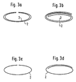
- the folded tapes 2 are shown in cross section above the roller 6 in FIG. 3a and in FIGS. 3a to 3d.
- the folded tapes are heated by the subsequent heated godet 6, so that the layers lying one on top of the other can additionally glue together.
- FIG 3 only four different folding devices 10, 11a, 11b, 11c, 11d are shown as examples.
- the folding device 10, 11a, two tapes 2 are fed, which only converge in the area of the folding device approximately congruently one above the other.
- the folding device 10, 11b, two congruent foil tapes lying one above the other are fed.
- FIG. 4 shows a folding device 10, 11 with which a single or two congruent foil tapes can be folded in such a way that the cross-sectional profile of the folded tapes shown in FIGS. 3a and 3c results.
- the folding plates 11 approach symmetrically in the passage direction as the radius of curvature becomes smaller up to a distance which corresponds approximately to the width of the unfolded middle part of the ribbons.
- the dashed lines 10 the area of the folding device is indicated, in which the curvature of the side parts causing the folding begins.
- FIG. 5 shows a folding device 10, 1, the folding sheets or folding parts 11 of which converge asymmetrically in the direction of travel as the radius of curvature becomes smaller up to a distance which corresponds approximately to the width of the unfolded middle part of the tapes 2.
- the asymmetrical formation of the parts serving for folding is indicated by the dashed line 10 ⁇ , which indicates the course of the beginning of the curvature.
- film tapes with a cross section according to FIGS. 3b and 3d can be folded in that, for example, when using a 9mm wide tape, the width of the thread guide at the exit is only about 3 mm.
- Fig.6 shows another device in which wider tapes of the coils 15, 15 'are unwound in such a way that they are fed approximately congruently one above the other to the folding device 10, 11.
- the wider unwound and superimposed tapes are pulled through the folding device 10, 11 and thereby folded onto themselves.
- the folded tapes are deflected in the manner shown and wound over a guide piece 16 onto a second spool 17 as a folded tape.
- the holder 18 for the folding device 10, 11, which is constructed in basically the same way as that described with reference to FIGS. 2 to 5, and the guide piece 16 are reciprocated in a housing 19 parallel to the axes of the coils 15, 17 movably mounted so that the coil 18 can be wound uniformly over the entire width.
- the wide tapes can of course also be delivered directly from a stretching section.
Landscapes
- Engineering & Computer Science (AREA)
- Mechanical Engineering (AREA)
- Textile Engineering (AREA)
- Laminated Bodies (AREA)
- Folding Of Thin Sheet-Like Materials, Special Discharging Devices, And Others (AREA)
- Shaping Of Tube Ends By Bending Or Straightening (AREA)
- Woven Fabrics (AREA)
- Treatment Of Fiber Materials (AREA)
- Decoration Of Textiles (AREA)
- Ropes Or Cables (AREA)
- Shaping By String And By Release Of Stress In Plastics And The Like (AREA)
- Air Bags (AREA)
- Materials For Medical Uses (AREA)
Description
- Die Erfindung betrifft ein Verfahren zur Herstellung zumindest einfach gefalteter Bändchen aus thermoplastischem Kunststoff, vorzugsweise zur Herstellung hochfester Gewebe, bei dem die Bändchen vor ihrem Aufspulen auf die zur Weiterverarbeitung vorgesehene Spule auf sich gefaltet werden.
- Großvolumige, sogenannte Containersäcke bestehen aus einem reißfesten Gewebe aus verstreckten Bändchen aus thermoplastischem Kunststoff, die diesem Gewebe eine so große Festigkeit verleihen, daß die Containersäcke mit Füllgewichten von beispielsweise mehr als 1t belastet werden können. Um die Füllgewichte noch weiter erhöhen zu können, ist es erforderlich, das Quadratmetergewicht des Gewebes zu erhöhen.
- Aus FR-A-1 306 629 ist ein Verfahren nach dem Oberbegriff des Patentanspruchs 1 zur Herstellung mehrlagiger, auf sich selbst gefalteter Bändchen aus thermoplastischem Kunststoff bekannt, bei dem die Bändchen verstreckt und vor oder nach ihrer Verstreckung auf sich gefaltet werden, wobei die Bändchen vor ihrem Aufspulen auf eine zur Weiterverarbeitung vorgesehene Spule und vor ihrer Thermofixierung auf sich gefaltet werden. Trotz der Thermofixierung läßt sich nicht mit Sicherheit ausschließen, daß die Bändchen später auffedern können, so daß sich Schwierigkeiten bei der Weiterverarbeitung ergeben.
- Aufgabe der Erfindung ist es daher, ein Verfahren der eingangs angegebenen Art zu schaffen, bei dem mit Sicherheit vermieden ist, daß sich die Bändchen nach ihrer Thermofixierung wieder auffalten.
- Erfindungsgemäß wird diese Aufgabe durch das kennzeichnende Merkmal des Patentanspruchs gelöst.
- Die Bändchen bestehen im wesentlichen aus einer Mischung aus 90-70% Polypropylen und 10-30% eines Kunstoffes. Propylene eignen sich besonders gut zur Herstellung von Bändchen, da insbesondere bei diesen durch uniaxiales Recken eine räumliche Orientierung der Ketten erreicht werden kann, die zu einer Festigkeitssteigerung führt. Andererseits neigen jedoch Polypropylenbändchen nach ihrer Faltung wieder zum Auffalten, da diese nicht oder nur wenig miteinander verkleben, und auch durch Thermofixierung die Faltung nicht sicher fixiert werden kann. Werden jedoch den Polypropylenen Kunststoffe, die unter Wärme eine größere Adhäsion aufweisen als das Grundmaterial Propylen, in einer Menge von 10 bis 30 % zugemischt, wird die Faltung stabil, da die aufeinandergefalteten Lagen unter Wärmeeinwirkung miteinander verkleben. Auf diese Weise wird die unerwünschte Auffaltung der gefalteten Bändchen mit Sicherheit vermieden.
- Eine Vorrichtung zur Herstellung von auf sich gefalteten, verstreckten und thermofixierten Bändchen nach dem erfindungsgemäßen Verfahren kann aus einem Streck- und Fixierwerk mit Galetten, über die die Bändchenschar in Form aufeinanderfolgender, gegensinnig offener Schlaufen läuft, bestehen. Dabei sind zwischen zwei Galetten Faltbleche geschaltet, von denen jedes aus einem zu dem einlaufenden Bändchen im wesentlichen parallelen Bodenblech und aus an dieses seitlich anschließenden, schalenförmigen Faltblechen besteht, deren Öffnungen einander zugewandt sind und die sich einander in Laufrichtung bei kleiner werdendem Krümmungsradius bis auf einen Abstand annähern, der etwa der Breite der ungefalteten Mittelteile der Bändchen entspricht. Soll ein einander überlappendes Falten der eingeschlagenen Seitenteile der Bändchen erfolgen, nähern sich die einander zugewandten schalenförmigen Faltbleche einander in Laufrichtung bei kleiner werdendem Krümmungsradius in unsymmetrischer Form bis auf einen Abstand an, der etwa der Breite der ungefalteten Mittelteile der Bändchen entspricht.
- Ausführungsbeispiele der Erfindung werden nachstehend anhand der Zeichnung näher erläutert. In dieser zeigt
- Fig. 1
- eine Seitenansicht einer Bändchenreckstrecke in schematischer Darstellung,
- Fig. 2
- eine zwischen zwei Galetten des Streckwerks der Bändchenreckanlage angeordnete Falteinrichtung für die Bändchen im Längsschnitt,
- Fig. 3
- eine Ansicht der Falteinrichtung in Richtung des Pfeils in Fig. 2.
- Fig.3a bis Fig.3d
- Schnitte durch die in den Falteinrichtungen gefalteten Bändchen zur Darstellung des Profils der gefalteten Bändchen,
- Fig.4
- eine Falteinrichtung zur symmetrischen Faltung der Bändchen in Draufsicht und Rückenansicht
- Fig.5
- eine Falteinrichtung zum überlappenden Falten der Seitenteile der Bändchen in Draufsicht und Rückansicht und
- Fig.6
- eine Vorrichtung zum Falten kalter verstreckter Bändchen auf sich selbst in schematischer Seitenansicht.
- In der schematisch dargestellten Bänchenreckanlage nach Fig.1 läuft eine Schar von aufeinanderliegenden Bändchen in Schlaufenform über die Walzen 1 eines Haltwerkes. Von dem Haltewerk läuft die Schar der übereinanderliegenden Bänchen 1 in einen Heißluftofen 3 ein, der üblicher Bauart ist. Die aus dem Heißluftofen 3 austretender Schar der Bändchen 2 durchläuft sodann ein sogenanntes Streck- und Fixierwerk 4. Dieses besteht aus den Galetten 5 bis 7, von denen eine oder mehrere beheizt sind. Die Galetten 5 bis 7 bilden das sogenannte Streckwerk. Im Anschluß an die letzte beheizte Walze oder Galette durchläuft die Schar der Bändchen 2 den sogenannten Fixierteil des Streck- und Fixierwerkes. Dieser wird durch die Galetten 8 und 9 gebildet, deren Umfangsgeschwindigkeit kleiner ist als die Umfangsgeschwindigkeit der letzten Galette 7 des Streckwerkes, so daß die einzelnen Bändchen 2 zurückschrumpfen können und dabei fixiert werden.
- Wie aus Fig.2 ersichtlich ist, ist zwischen der Galette 5, auf die die übereinander liegenden Bändchen auflaufen, und der Galette 6 eine Einrichtung zum Falten der einzelnen Bändchen vorgesehen. Diese Einrichtung besteht im wesentlichen aus einer ebenen Grundplatte 10, die von einer in Laufrichtung der Bändchen zusammenlaufenden geschlitzten konischen Abdeckung 11 umgeben ist. Das Faltstück ist auf einem gehäusefesten Träger 12 einstellbar montiert, der, wie aus Fig.3 ersichtlich ist, seitliche Schwenkarme 13 aufweist. In diesen seitlichen Schwenkarmen 13 ist eine Walze 14 gelagert, die in nicht dargestellter Weise sowohl in der mit vollen Linien dargestellten Arbeitsstellung als auch in der inneren neutralen Stellung festgelegt werden kann. Durch die Falteinrichtung werden die Bändchen 2 auf sich gefaltet. Die gefalteten Bändchen 2 sind oberhalb der Walze 6 in Fig.3 und in den Fig.3a bis 3d im Querschnitt dargestellt. Die gefalteten Bändchen werden durch die nachfolgende beheizte Galette 6 aufgeheizt, so daß die aufeinanderliegenden Lagen zusätzlich noch miteinander verkleben können.
- In Fig.3 sind nur beispielhaft vier unterschiedliche Falteinrichtungen 10,11a, 11b, 11c, 11d dargestellt. Der Falteinrichtung 10, 11a, werden zwei Bändchen 2 zugeführt, die erst im Bereich der Falteinrichtung etwa deckungsgleich übereinanderliegend zusammenlaufen.
- Der Falteinrichtung 10, 11b, werden zwei deckungsgleiche übereinander liegende Folienbändchen zugeführt.
- In die Falteinrichtungen 10,11c und 10,11d laufen einlagige Folienbändchen ein, wobei die Falteinrichtung 10,11d die Seitenteile des Folienbändchens derart einander überlappend einschlägt, daß sich ein dreilagiges Folienbändchen mit dem aus Fig.3d ersichtlichen Querschnitt ergibt.
- Aus Fig.4 ist eine Falteinrichtung 10,11 ersichtlich, mit dem ein einzelnes oder zwei deckungsgleich übereinanderliegende Folienbändchen derart gefaltet werden können, daß sich das aus den Fig.3a und 3c ersichtliche Querschnittsprofil der gefalteten Bändchen ergibt. Zu diesem Zweck nähern sich bei der Falteinrichtung 10,11 nach Fig.4 die Faltbleche 11 in Durchlaufrichtung bei kleiner werdendem Krümmungsradius symmetrisch bis auf einen Abstand an, der etwa der Breite des ungefalteten Mittelteils der Bändchen entspricht. In Fig.4 ist durch die gestrichelten Linien 10′ der Bereich der Falteinrichtung angedeutet, in dem die Krümmung der die Faltung bewirkenden Seitenteile beginnt.
- Aus Fig.5 ist eine Falteinrichtung 10,11 ersichtlich, dessen Faltbleche oder Einfaltteile 11 sich einander in Laurichtung bei kleiner werdendem Krümmungsradius unsymmetrisch bis auf einen Abstand einander annähern, der etwa der Breite des ungefalteten Mittelteils der Bändchen 2 entspricht. Die unsymmetrische Ausbildung der der Faltung dienenden Teile ist durch die gestrichelte Linie 10˝ angedeutet, die den Verlauf des Beginns der Krümmung anzeigt.
- Auch mit der Falteinrichtung nach Fig.4 lassen sich Folienbändchen mit einem Querschnitt nach den Fig.3b und 3d dadurch falten, daß beispielsweise bei Verwendung eines 9mm breiten Bändchens die Breite des Fadenführers am Ausgang nur etwa 3 mm beträgt.
- Durch Verwenden von Faltblechen, die an ihrem Ausgang schmaler sind als die Hälfte der Bändchenbreite, lassen sich Mehrfachfaltungen erreichen, die aber nicht immer in genau kontrollierter Weise erfolgen.
- Fig.6 zeigt eine andere Vorrichtung, bei der breitere Bändchen von den Spulen 15,15′ in der Weise abgewickelt werden, daß diese etwa deckungsgleich übereinanderliegend der Falteinrichtung 10,11 zugeführt werden. Die breiteren abgewickelten und übereinanderliegenden Bändchen werden durch die Falteinrichtung 10,11 gezogen und dadurch auf sich gefaltet. Die gefalteten Bändchen werden in der dargestellten Weise umgelenkt und über ein Führungsstück 16 auf eine zweite Spule 17 als auf sich gefaltete Bändchen aufgewickelt. Der Halter 18 für die Falteinrichtung 10,11, die in grundsätzlich gleicher Weise aufgebaut ist, wie die anhand der Fig.2 bis 5 beschriebenen, und das Führungsstück 16 sind in einem Gehäuse 19 parallel zu den Achsen der Spulen 15,17 hin- und herbewegbar gelagert, um die Spule 18 über die gesamte Breite gleichmäßig bewickeln zu können.
- Anstatt von den Spulen 15,15′ können die breiten Bändchen selbstverständlich auch direkt von einer Reckstrecke angeliefert werden.
Claims (1)
- Verfahren zur Herstellung zumindest einfach gefalteter Bändchen aus thermoplastischem Kunststoff, vorzugsweise zur Herstellung hochfester Gewebe, bei dem die Bändchen vor ihrem Aufspulen auf die zur Weiterverarbeitung vorgesehene Spule auf sich gefaltet werden,
dadurch gekennzeichnet,
daß die Bändchen im wesentlichen aus einer Mischung aus 90 - 70 % Polypropylen und 10 - 30 % eines Kunststoffes bestehen, der unter Wärme eine größere Adhäsion aufweist als das Grundmaterial Polypropylen.
Applications Claiming Priority (4)
| Application Number | Priority Date | Filing Date | Title |
|---|---|---|---|
| DE3842764 | 1988-12-19 | ||
| DE3842764 | 1988-12-19 | ||
| DE3909092A DE3909092A1 (de) | 1988-12-19 | 1989-03-20 | Verfahren und vorrichtung zur herstellung mehrlagiger verstreckter baendchen |
| DE3909092 | 1989-03-20 |
Publications (3)
| Publication Number | Publication Date |
|---|---|
| EP0374599A2 EP0374599A2 (de) | 1990-06-27 |
| EP0374599A3 EP0374599A3 (de) | 1991-02-27 |
| EP0374599B1 true EP0374599B1 (de) | 1995-08-02 |
Family
ID=25875344
Family Applications (1)
| Application Number | Title | Priority Date | Filing Date |
|---|---|---|---|
| EP89122562A Expired - Lifetime EP0374599B1 (de) | 1988-12-19 | 1989-12-07 | Verfahren zur Herstellung mehrlagiger verstreckter Bändchen |
Country Status (9)
| Country | Link |
|---|---|
| US (1) | US5085566A (de) |
| EP (1) | EP0374599B1 (de) |
| JP (1) | JPH02210081A (de) |
| CN (1) | CN1025597C (de) |
| AT (1) | ATE125774T1 (de) |
| BR (1) | BR8906546A (de) |
| CA (1) | CA2005797C (de) |
| DE (2) | DE3909092A1 (de) |
| ES (1) | ES2075846T3 (de) |
Families Citing this family (7)
| Publication number | Priority date | Publication date | Assignee | Title |
|---|---|---|---|---|
| JP3498879B2 (ja) * | 1995-12-27 | 2004-02-23 | 本田技研工業株式会社 | 車両用シートベルト装置 |
| DE19756257A1 (de) * | 1997-12-17 | 1999-07-01 | Sahm Georg Fa | Verfahren und Vorrichtung zur Herstellung von mehrlagigen Bändchen aus Kunststoff |
| US6319457B1 (en) * | 1999-08-27 | 2001-11-20 | Viskase Corporation | Method for extruding tubular film |
| ITBO20040790A1 (it) * | 2004-12-23 | 2005-03-23 | S I M A Societa Ind Meccaniche | Apparato ad ingombro contenuto per il trascinamento dei nastri di materia plastica ad esempio di propilene o di poetilene nei procedimenti noti per la produzione di reggetta rafia o d'altri tipi di nastri |
| PT1915249E (pt) * | 2005-11-21 | 2008-11-25 | Lohia Starlinger Ltd | Método para a produção de fitas de película cortada orientadas |
| CN104552903A (zh) * | 2013-10-09 | 2015-04-29 | 常州市伟宇精密机械有限公司 | 一种薄膜拉丝机及塑料扁丝的折叠方法 |
| CN107723922A (zh) * | 2017-11-30 | 2018-02-23 | 际华三五五皮革皮鞋有限公司 | 一种穿条制作设备及穿条制作方法 |
Family Cites Families (21)
| Publication number | Priority date | Publication date | Assignee | Title |
|---|---|---|---|---|
| NL127318C (de) * | 1958-09-24 | |||
| FR1306629A (fr) * | 1961-05-17 | 1962-10-19 | Dow Chemical Co | Procédé pour l'obtention de microbandes filamentaires de section transversale labyrinthique et microbandes obtenues par ce procédé |
| US3372222A (en) * | 1965-08-06 | 1968-03-05 | Dow Chemical Co | Process for preparing filamentary microtapes of labyrinthian cross section |
| DE1510636A1 (de) * | 1965-09-01 | 1970-04-09 | Hoechst Ag | Dekorativer Textilstrang und daraus hergestellte Gewebe |
| US3356783A (en) * | 1966-02-04 | 1967-12-05 | Dow Chemical Co | Process for preparing filamentary microtapes of labyrinthian cross section |
| US3448187A (en) * | 1966-08-26 | 1969-06-03 | Dow Chemical Co | Process for preparing filamentary microtapes of labyrinthian cross section |
| GB1182352A (en) * | 1967-01-31 | 1970-02-25 | Ici Ltd | Production of Coherent Elongated Shaped Structures from Ribbons or Tapes |
| GB1172038A (en) * | 1967-11-09 | 1969-11-26 | Ici Ltd | Process for the Production of Oriented Polyolefin Tapes |
| US3514368A (en) * | 1968-03-27 | 1970-05-26 | Acme Backing Corp | Laminated plastic yarns and method and apparatus for making the same |
| US3503106A (en) * | 1968-06-27 | 1970-03-31 | Avisun Corp | Continuous techniques for making flat woven synthetic fabrics |
| FR2094490A5 (en) * | 1970-06-23 | 1972-02-04 | Seine & Lys | Packaging string - formed from extruded expanded polyolefine sheet |
| JPS4828757A (de) * | 1971-08-25 | 1973-04-16 | ||
| FR2158727A5 (de) * | 1971-10-29 | 1973-06-15 | Cohen Elie | |
| JPS49114671A (de) * | 1973-03-05 | 1974-11-01 | ||
| JPS5259749A (en) * | 1975-11-11 | 1977-05-17 | Katagi Goseikagaku Kk | Synthetic resin twistless string and its manufacture |
| JPS5844128Y2 (ja) * | 1979-03-16 | 1983-10-06 | クロバ−株式会社 | 裁縫用バイアステ−プ作成具 |
| US4252550A (en) * | 1979-05-01 | 1981-02-24 | Glaswerk Schuller Gmbh | Method and apparatus for the integration of newly formed filaments into a continuous strand |
| GB8426351D0 (en) * | 1984-10-18 | 1984-11-21 | Lamberg Ind Res Ass | Treating tape |
| JPH0713323B2 (ja) * | 1985-08-22 | 1995-02-15 | 三菱油化株式会社 | ポリプロピレン延伸テ−プヤ−ンの製造方法 |
| FR2599295B1 (fr) * | 1986-05-27 | 1988-12-23 | Gennesson Patrick | Procede de fabrication d'un film plastique pour notamment la solidarisation temporaire de plusieurs produits et le film obtenu par le procede |
| GB2193734A (en) * | 1986-08-07 | 1988-02-17 | Orbit Weaving Machinery Limite | Fabric folding machine |
-
1989
- 1989-03-20 DE DE3909092A patent/DE3909092A1/de not_active Withdrawn
- 1989-12-07 EP EP89122562A patent/EP0374599B1/de not_active Expired - Lifetime
- 1989-12-07 ES ES89122562T patent/ES2075846T3/es not_active Expired - Lifetime
- 1989-12-07 DE DE58909371T patent/DE58909371D1/de not_active Expired - Fee Related
- 1989-12-07 AT AT89122562T patent/ATE125774T1/de not_active IP Right Cessation
- 1989-12-15 CN CN89109747A patent/CN1025597C/zh not_active Expired - Fee Related
- 1989-12-18 US US07/451,344 patent/US5085566A/en not_active Expired - Lifetime
- 1989-12-18 BR BR898906546A patent/BR8906546A/pt not_active IP Right Cessation
- 1989-12-18 CA CA002005797A patent/CA2005797C/en not_active Expired - Fee Related
- 1989-12-19 JP JP1329379A patent/JPH02210081A/ja active Pending
Also Published As
| Publication number | Publication date |
|---|---|
| CN1025597C (zh) | 1994-08-10 |
| US5085566A (en) | 1992-02-04 |
| DE58909371D1 (de) | 1995-09-07 |
| JPH02210081A (ja) | 1990-08-21 |
| CA2005797A1 (en) | 1990-06-19 |
| ES2075846T3 (es) | 1995-10-16 |
| EP0374599A2 (de) | 1990-06-27 |
| CA2005797C (en) | 1999-06-01 |
| EP0374599A3 (de) | 1991-02-27 |
| BR8906546A (pt) | 1990-09-04 |
| CN1043660A (zh) | 1990-07-11 |
| DE3909092A1 (de) | 1990-06-21 |
| ATE125774T1 (de) | 1995-08-15 |
Similar Documents
| Publication | Publication Date | Title |
|---|---|---|
| DE2721771C2 (de) | Verfahren zur Herstellung einseitig offener Säcke mit einem tragenden Außensack und einem dichtenden Innensack | |
| EP0498962A1 (de) | Verfahren und Einrichtung zur Herstellung eines Wickels | |
| DE602006000666T2 (de) | Vorrichtung und Verfahren zur Herstellung von wellenförmigen Bändern | |
| DE69001697T2 (de) | Einwickeln von laenglichen gegenstaenden. | |
| DE69824869T2 (de) | Verfahren zur herstellung dehnbarer verpackungsfolien | |
| EP0374599A2 (de) | Verfahren zur Herstellung mehrlagiger verstreckter Bändchen | |
| EP0307785B1 (de) | Verfahren und Vorrichtung zur Herstellung doppellagiger verstreckter Bändchen | |
| EP0101575A2 (de) | Spiralband | |
| DE3106947A1 (de) | "spulvorrichtung zum aufspulen von flachfaeden zu zylindrischen kreuzspulen" | |
| DE1635481B2 (de) | Maschine zur herstellung eines endlosen fadengeleges | |
| DE2151071A1 (de) | Verfahren und Vorrichtung zur Herstellung einachsig verstreckter,nur schwer in Laengsrichtung schlitzbarer Erzeugnisse | |
| DE69009906T2 (de) | Tragetasche mit in den verstärkungsbereichen ausgeschnittenen grifflöchern sowie verfahren und vorrichtung zu ihrer herstellung. | |
| DE2144694A1 (de) | ||
| EP0196492A1 (de) | Verfahren und Einrichtung zur Erzeugung eines rohrförmigen Halbfabrikates aus Kunststoff für die Herstellung von Säcken | |
| DE3821404A1 (de) | Verfahren und vorrichtung zur herstellung doppelagiger verstreckter baendchen | |
| EP1015369B1 (de) | Verfahren und vorrichtung zur herstellung von mehrlagigen bändchen aus kunststoff | |
| DE3742915A1 (de) | Verfahren und vorrichtung zur herstellung doppellagiger verstreckter baendchen | |
| AT392806B (de) | Sackgewebe | |
| CH715759A1 (de) | Hybrid-Garn sowie Vorrichtung und Verfahren zur Herstellung eines Hybridgarns. | |
| WO2008119570A2 (de) | Einrichtung zum flachlegen eines folienschlauches zu einem flachmaterial | |
| DE2720631C2 (de) | Verfahren und Vorrichtung zur Herstellung eines Klebfutters für versteifende Ausfütterungen von Bekleidungen und Möbeln | |
| DE2236286B2 (de) | Vliesstoffverstärktes Papier mit einer Verstärkung aus einem offenen Netzwerk | |
| DE2807590C3 (de) | Tütenband sowie Verfahren und Vorrichtung zur Herstellung eines solchen | |
| DE2840664C2 (de) | Verfahren und Vorrichtung zum Ablegen von laufenden Filament- oder Faserkabeln | |
| DE2827160A1 (de) | Rohrfoermige verpackung |
Legal Events
| Date | Code | Title | Description |
|---|---|---|---|
| PUAI | Public reference made under article 153(3) epc to a published international application that has entered the european phase |
Free format text: ORIGINAL CODE: 0009012 |
|
| AK | Designated contracting states |
Kind code of ref document: A2 Designated state(s): AT DE ES FR GB IT |
|
| PUAL | Search report despatched |
Free format text: ORIGINAL CODE: 0009013 |
|
| AK | Designated contracting states |
Kind code of ref document: A3 Designated state(s): AT DE ES FR GB IT |
|
| 17P | Request for examination filed |
Effective date: 19910326 |
|
| 17Q | First examination report despatched |
Effective date: 19921105 |
|
| GRAA | (expected) grant |
Free format text: ORIGINAL CODE: 0009210 |
|
| AK | Designated contracting states |
Kind code of ref document: B1 Designated state(s): AT DE ES FR GB IT |
|
| REF | Corresponds to: |
Ref document number: 125774 Country of ref document: AT Date of ref document: 19950815 Kind code of ref document: T |
|
| REF | Corresponds to: |
Ref document number: 58909371 Country of ref document: DE Date of ref document: 19950907 |
|
| GBT | Gb: translation of ep patent filed (gb section 77(6)(a)/1977) |
Effective date: 19950814 |
|
| ITF | It: translation for a ep patent filed | ||
| REG | Reference to a national code |
Ref country code: ES Ref legal event code: FG2A Ref document number: 2075846 Country of ref document: ES Kind code of ref document: T3 |
|
| ET | Fr: translation filed | ||
| PLBE | No opposition filed within time limit |
Free format text: ORIGINAL CODE: 0009261 |
|
| STAA | Information on the status of an ep patent application or granted ep patent |
Free format text: STATUS: NO OPPOSITION FILED WITHIN TIME LIMIT |
|
| 26N | No opposition filed | ||
| PGFP | Annual fee paid to national office [announced via postgrant information from national office to epo] |
Ref country code: DE Payment date: 19990318 Year of fee payment: 11 |
|
| PGFP | Annual fee paid to national office [announced via postgrant information from national office to epo] |
Ref country code: GB Payment date: 19991122 Year of fee payment: 11 |
|
| PGFP | Annual fee paid to national office [announced via postgrant information from national office to epo] |
Ref country code: FR Payment date: 19991216 Year of fee payment: 11 Ref country code: ES Payment date: 19991216 Year of fee payment: 11 |
|
| PGFP | Annual fee paid to national office [announced via postgrant information from national office to epo] |
Ref country code: AT Payment date: 19991220 Year of fee payment: 11 |
|
| PG25 | Lapsed in a contracting state [announced via postgrant information from national office to epo] |
Ref country code: GB Free format text: LAPSE BECAUSE OF NON-PAYMENT OF DUE FEES Effective date: 20001207 Ref country code: AT Free format text: LAPSE BECAUSE OF NON-PAYMENT OF DUE FEES Effective date: 20001207 |
|
| GBPC | Gb: european patent ceased through non-payment of renewal fee |
Effective date: 20001207 |
|
| PG25 | Lapsed in a contracting state [announced via postgrant information from national office to epo] |
Ref country code: FR Free format text: LAPSE BECAUSE OF NON-PAYMENT OF DUE FEES Effective date: 20010831 |
|
| REG | Reference to a national code |
Ref country code: FR Ref legal event code: ST |
|
| PG25 | Lapsed in a contracting state [announced via postgrant information from national office to epo] |
Ref country code: DE Free format text: LAPSE BECAUSE OF NON-PAYMENT OF DUE FEES Effective date: 20011002 |
|
| PG25 | Lapsed in a contracting state [announced via postgrant information from national office to epo] |
Ref country code: ES Free format text: LAPSE BECAUSE OF NON-PAYMENT OF DUE FEES Effective date: 20011208 |
|
| REG | Reference to a national code |
Ref country code: ES Ref legal event code: FD2A Effective date: 20020112 |
|
| PG25 | Lapsed in a contracting state [announced via postgrant information from national office to epo] |
Ref country code: IT Free format text: LAPSE BECAUSE OF NON-PAYMENT OF DUE FEES;WARNING: LAPSES OF ITALIAN PATENTS WITH EFFECTIVE DATE BEFORE 2007 MAY HAVE OCCURRED AT ANY TIME BEFORE 2007. THE CORRECT EFFECTIVE DATE MAY BE DIFFERENT FROM THE ONE RECORDED. Effective date: 20051207 |