EP0367551A2 - Système de commande pour convertisseur de couple d'une transmission automatique - Google Patents
Système de commande pour convertisseur de couple d'une transmission automatique Download PDFInfo
- Publication number
- EP0367551A2 EP0367551A2 EP89311216A EP89311216A EP0367551A2 EP 0367551 A2 EP0367551 A2 EP 0367551A2 EP 89311216 A EP89311216 A EP 89311216A EP 89311216 A EP89311216 A EP 89311216A EP 0367551 A2 EP0367551 A2 EP 0367551A2
- Authority
- EP
- European Patent Office
- Prior art keywords
- hydraulic pressure
- spool
- pressure
- control
- control system
- Prior art date
- Legal status (The legal status is an assumption and is not a legal conclusion. Google has not performed a legal analysis and makes no representation as to the accuracy of the status listed.)
- Granted
Links
Images


Classifications
-
- F—MECHANICAL ENGINEERING; LIGHTING; HEATING; WEAPONS; BLASTING
- F16—ENGINEERING ELEMENTS AND UNITS; GENERAL MEASURES FOR PRODUCING AND MAINTAINING EFFECTIVE FUNCTIONING OF MACHINES OR INSTALLATIONS; THERMAL INSULATION IN GENERAL
- F16H—GEARING
- F16H61/00—Control functions within control units of change-speed- or reversing-gearings for conveying rotary motion ; Control of exclusively fluid gearing, friction gearing, gearings with endless flexible members or other particular types of gearing
- F16H61/14—Control of torque converter lock-up clutches
- F16H61/143—Control of torque converter lock-up clutches using electric control means
Definitions
- the present invention relates to a torque converter for an automatic transmission having a lock-up clutch, more specifically to a slip control valve system for the lock-up clutch.
- a lock-up clutch mechanism for providing a direct connection between engine output member and input member of the transmission under a predetermined vehicle operating condition wherein there occurs no amplification of a torque, or no change in torque from an engine so that a fuel consumption performance of the vehicle is improved.
- the lock-up clutch mechanism When the lock-up clutch mechanism is engaged, the torque from the engine is transmitted bypassing the torque converter to the transmission through the lock-up clutch mechanism.
- the fuel consumption performance can be improved because there is no energy loss caused by a fluid friction in the torque converter.
- Japanese Patent Public Disclosure (KOKAI) No. 62-297567 laid open to the public on December 24, 1987, discloses a slip control system for a transmission of motor vehicle having a torque converter and lock-up clutch mechanism wherein the lock-up clutch mechanism is constituted by a converter cover connected with an engine output shaft and a damper piston connected with a turbine shaft with the damper piston being brought into frictional engagement with the converter cover in accordance with a hydraulic pressure introduced into hydraulic chambers formed at front and back side of the damper piston.
- the transmission is adapted to carries out a slip control in which the lock-up clutch allows a certain slippage so as to take selectively a lock-up condition wherein an engine torque is transmitted through only the lock-up clutch mechanism, a converter condition wherein the engine torque is transmitted through only the torque converter and a slip condition wherein the engine torque is transmitted through both the lock-up clutch and the torque converter.
- Japanese Patent Public Disclosure No. 57-33253 (corresponding to U.S.P. No.4,468,988 issued on September 4, 1984) laid open to the public in 1982, discloses a slip control system for establishing a proper slip condition wherein respective rotation speeds of an input and output members of the torque converter are detected and a hydraulic pressure for controlling the lock-up clutch is controlled for converging a rotation speed difference between the input and output members to a predetermined value by means of a feedback control.
- U.S.P. Nos.4,580,671, 4,618,041, 4,669,441, 4,687,083, and 4,468,988 also disclose conventional transmission control systems respectively.
- a control system for a torque converter of an automatic transmission comprising lock-up clutch device provided in a torque converter for connecting an input and output members of the torque converter directly, engaging disengaging hydraulic device for controlling an engaging and disengaging action of the lock-up clutch device, shift valve device provided with a first and second spools in series for controlling an introduction of a driving hydraulic pressure introduced into the hydraulic device, said first spool being subjected to a first hydraulic pressure at a first end thereof, the second spool being subjected to a second hydraulic pressure at a second end thereof opposite to said first end of the first spool, said first and second spool being subjected to a third hydraulic pressure therebetween, first control device for controlling said first hydraulic pressure, second control device for controlling said second hydraulic pressure, adjusting valve for controlling the driving hydraulic pressure introduced into the engaging or disengaging hydraulic device, third control device for controlling a hydraulic pressure for controlling the adjusting valve.
- the first and second spools are moved in the same direction when the first control device changes the first hydraulic pressure from high to low or low to high.
- the first spool stays at its position and only the second spool is moved by virtue of the third hydraulic pressure.
- the shift valve can take selectively a first position wherein both the first and second spool are positioned at one side in a bore of the shift valve, a second position wherein the first and second spool are positioned at the other side in the bore, and a third position wherein the first spool is positioned at the one side and the second spool is positioned at the other side.
- the shift valve selectively takes the three different positions of the spools in accordance with vehicle operating condition to switch a hydraulic pressure introducing path for the lock-up clutch mechanism so that the lock-up mechanism establishes a lock-up condition when a hydraulic pressure is introduced only into the engaging hydraulic device, a converter condition when a hydraulic pressure is introduced only to the disengaging hydraulic device and a slip condition when a hydraulic pressure is introduced into both the engaging and disengaging hydraulic devices.
- the third control device controls a controlling hydraulic pressure for the adjusting valve so that the adjusting valve adjusts the hydraulic pressure for the disengaging device based on the controlling hydraulic pressure.
- This control of the hydraulic pressure for the disengaging device enables a pressure difference between the engaging and disengaging device to be changed during the slip condition so that a slippage in the lock-up clutch mechanism during the slip condition can be controlled with or without step.
- the third control device may be controlled by means of a feedback control in which a speed difference between engine and turbine speed is detected for the better slip control.
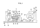
- FIG. 1 there is shown a schematic view of an automatic transmission 10.
- the transmission 10 is provided with a torque converter 20 and a multiple stage transmission gear mechanism 30.
- the gear mechanism 30 is provided with a plurality of frictional element such as clutch, brake and the like for switching a power transmitting path to selectively establish a desirable gear stage among a first through fourth stage in a range D, the first through third stage in a range 2, the first and the second stage in a range 1, and a range R.
- the torque converter 20 is provided with a pump 22 mounted on one side of a case 21 fixed to an engine output shaft 1 for rotating together with the shaft 1, a turbine 23 facing the pump 22 and rotatably mounted on the other side of the case 21 for being driven by the pump 22 through a hydraulic oil, and a stator disposed between the pump 22 and the turbine 23 for amplifying the torque when a speed ratio of the turbine 23 to the pump 22 is smaller than a predetermined value.
- the torque converter 20 is also provided with a lock-up clutch 26 for directly connecting the engine output shaft 1 or an input member of the torque converter and a turbine 23 or an output member of the torque converter 20.
- the gear mechanism 30 is constituted by Ravigneaux-type planetary gear mechanism.
- the gear mechanism 30 is provided with a small sun gear 31 slidably mounted on the turbine shaft 27 and a large sun gear 32 slidably mounted on the turbine shaft 27 at a rear position of the small sun gear 31, a plurality of short pinion gears 33 meshed with the small sun gear 31, long pinion gear meshed with the short pinion gears 33 at a front portion and with the large sun gear 32 at a rear portion thereof, a carrier 35 rotatably carrying the long pinion gear 34 and the short pinion gears 33, and a ring gear 36 meshed with a front portion of the long pinion gear 34.
- a forward clutch 41 and a first one-way clutch 51 in series between the turbine shaft 27 and the small sun gear 31.
- a coast clutch 42 in parallel with the clutches 41 and 51.
- a reverse clutch 44 is disposed between the turbine shaft 27 and the large sun gear 32.
- a 2-4 brake 45 constituted a band brake is provided between the large sun gear 32 and the reverse clutch 44 for fixing the large sun gear 32.
- a 3-4 clutch 43 is disposed between the turbine shaft 27 and the carrier 35.
- a second one-way clutch 52 and a low & reverse brake 46 for fixing the carrier 35 in parallel with each other.
- the ring gear 36 is connected with an output gear 14 so that a rotative power is transmitted from the output gear 14 to
- the forward clutch 41 is engaged and the first and second one-way clutches 51 and 52 are locked.
- the output torque of the torque converter 20 is introduced from the turbine shaft 27 to the small sun gear 31 of the planetary gear mechanism through the forward clutch 41 and the one-way clutch 51.
- the carrier 35 is locked by virtue of the second one-way clutch 52 so that no differential operation occurs in the planetary gear mechanism when the power is tansmitted from the small sun gear 31 to the ring gear 36 through the short pinion gear 33 and the long pinion gear 34.
- the first gear stage having a large reduction speed ratio corresponding to a gear ratio of the small sun gear 31 to the ring gear 36 can be obtained.
- the forward clutch 41 is engaged to lock the one-way clutch 51 and the 2-4 brake 45 is engaged to fix the large sun gear 32 and to race the second one-way clutch 52.
- the power transmitted from the turbine shaft 27 to the small sun gear 31 is transmitted to the long pinion gear 34 through the short sun gear 33 to rotate the long pinion gear 34 around the large sun gear 32 which is fixed in this situation.
- the carrier 35 is rotated.
- the rotation speed of the ring gear 36 is increased compared with the first stage due to the rotation of the carrier 35 (rotation of the long pinion gear around the large sun gear 32) so that the second stage having a smaller reduction speed ratio than the first stage can be established.
- the 2-4 brake 45 is disengaged and the 3-4 clutch 43 is engaged in the above mentioned condition of the second stage.
- the rotative power of the turbine shaft 27 is transmitted to the small sun gear 31 through the forward clutch 41 and the first one-way clutch 51 and concurrently to the carrier 35 through the 3-4 clutch 43.
- the planetary gear mechanism is integrally rotated as if one piece parts so that the third stage in which the ring gear 36 is rotated with the same speed as the turbine shaft 27.
- the 2-4 brake 45 which is disengaged in the third stage is engaged again.
- the rotation of the turbine shaft 27 is transmitted to the carrier 35 from the 3-4 clutch 43 to rotate the long pinion gear 34 around the large sun gear 32.
- the large sun gear 32 is fixed by the 2-4 brake 45 so that the long pinion gear 34 is rotated around the large sun gear 32 and concurrently rotated by itself.
- This causes the rotation of the ring gear 36 meshed with the long pinion gear 34 to be increased by the self-rotation of the long pinion gear 34 in addition to the rotation of the carrier 35 ( rotation of the turbine shaft) so that the fourth stage of an over drive condition can be established.
- the reverse clutch 44 and the low & reverse brake 46 are engaged so that the rotation of the turbine shaft 27 is introduced into the large sun gear 32 and the carrier 35 is fixed. Consequently, the rotation is transmitted through an integrated gear train or through the large sun gear 32 and the long pinion gear 34 to the ring gear 36 so that a speed reduction ratio corresponding to a gear ratio of the ring gear 36 to the large sun gear 32 can be obtained. In this case, the ring gear 36 is rotated in a direction opposite to those of the turbine shaft 27 and the large sun gear 32. Thus, the reverse condition can be established.
- the one-way clutch 51 which transmits the rotation in the first through the third stage and the second one-way clutch 52 which bears a counter force in the first stage race under a coasting condition of the vehicle.
- the coast clutch 42 in parallel with the one-way clutch 51 is engaged in the third stage of the range D, the second and third stages of the range 2, the first and second stages of the range 1 and the low & reverse brake 46 in parallel with the second one-way clutch 52 is engaged in the first stage of the range 1 so that an engine brake effect can be obtained in those conditions.
- the table 1 shows a relationship between the respective gear stages and operations of the frictional elements 41-46 and the one-way clutches 51 and 52 of the transmission.
- reference * means that the corresponding element is raced under a coasting condition.
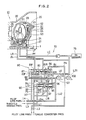
- FIG. 2 shows a hydraulic control circuit 70 for controlling the lock-up clutch 26.
- the hydraulic circuit 70 is incorporated into an entire hydraulic control unit for controlling the whole automatic transmission as a part of it. Hydraulic control circuits for controlling a hydraulic pressure introduced into actuators of the respective frictional elements 41-46 are omitted from the illustration.
- the torque converter 20 is provided with the lock-up clutch 26 between the turbine 23 and the converter cover 61.
- the lock-up clutch 26 is constituted by a torsion damper 63 rotating integrally with the turbine shaft 27, a damper piston 62, and a friction plate (not shown) facing to a peripheral portion of the damper piston 62.
- the damper piston 62 divides an inner space of the converter cover 61 into a R-chamber 65 adjacent to the turbine 23 and a F-chamber 64 adjacent to the converter cover 61.
- the damper piston 62 is brought into a frictional engagement with the frictional plate by an engaging force in accordance with a pressure difference between the R-chamber 65 and the F-chamber 64.
- the lock-up clutch 26 selectively takes, according to the frictional engaging condition, a lock-up condition or engaged clutch condition wherein the rotation of the engine output shaft 1 is directly transmitted to the turbine shaft 27, a converter condition or disengaged clutch condition wherein the rotation of the engine output shaft 1 is transmitted to the turbine shaft 27 through the converter cover 61 and the turbine 23, and a slip condition wherein the converter cover 61 is brought into slidable engagement with the damper piston 62 so that the rotation of the engine output shaft 1 is transmitted through the pump 22 and the turbine 23 and partially through the lock-up clutch 26 to the turbine shaft 27.
- the hydraulic circuit 70 is provided with a lock-up shift valve 80 which selectively takes three positions corresponding to the above three conditions of the lock-up clutch 26, a lock-up control valve 90 for introducing a hydraulic pressure into the F-chamber 64 through the shift valve 80, a duty solenoid valve 101 for controlling a second pilot pressure of the shift valve 80 and the control valve 90 by means of a duty control, and a lock-up solenoid valve 102 for controlling a first pilot pressure of the shift valve 80 by means of an ON-OFF control.
- the three positions of the shift valve 80 mean a first position wherein the hydraulic pressure is introduced only into the R-chamber 65, a second position wherein the hydraulic pressure is introduced only into the F-chamber 64, and a third position wherein the hydraulic pressure is introduced into both the R-chamber 65 and the F-chamber 64.
- the hydraulic circuit 70 is provided with various hydraulic passages such as, a torque converter line L1 in which a hydraulic pressure from the pump 22 is adjusted to a predetermined line pressure by virtue of a regulator valve (not shown), a first pilot line L2 for introducing the first pilot pressure into the shift valve 80, a throttle modulator line L3 into which a throttle modulator pressure adjusted to a value corresponding to a throttle opening of the engine through a throttle modulator valve and a duty solenoid valve (not shown) is introduced, and a second pilot line L4 into which a predetermined second pilot pressure is introduced after being reduced by virtue of a solenoid reducing valve (not shown).
- a torque converter line L1 in which a hydraulic pressure from the pump 22 is adjusted to a predetermined line pressure by virtue of a regulator valve (not shown)
- a first pilot line L2 for introducing the first pilot pressure into the shift valve 80
- a throttle modulator line L3 into which a throttle modulator pressure adjusted to a value corresponding to a throttle opening of the engine
- the torque converter line L1 is divided into a line L11 connected to a port 82R of the shift valve 80 and a line L12 connected to a port 92F of the control valve 90.
- spools 83 and 84 of the shift valve 80 are positioned at a right position or the first position. In this position, a port 81R is connected to the port 82R so that the line L11 introduces a hydraulic pressure of the torque converter into a line LR through the ports 81R and 82R.
- the line LR is connected with the R-chamber 65 through the pump 22 of the torque converter 20.
- the line LF is connected with the F-chamber 64.
- the hydraulic pressures in the R-chamber 65 and the F-chamber 64 are determined by the hydraulic pressures from the lines LR and LF. Since the lock-up clutch 26 is operated by an engaging force corresponding to a pressure difference between the R-chamber 65 and the F-chamber 64, the lock-up engaging force is determined by a pressure difference between a line pressure Pr of the line LR and a line pressure Pf of the line LF.
- the shift valve 80 provides only the line LR with the torque converter pressure so that the pressure difference between the R-chamber 65 and the F-chamber 64 is maximized.
- the lock-up condition or the engaged condition of the lock-up clutch 26 can be established.
- the first pilot line L2 is connected with a port 86 of the shift valve 80 through an orifice and with the solenoid valve 102 through a line L21.
- the solenoid valve 102 allows the first pilot line L2 to be drained in the ON-condition thereof so that the pilot pressure acting on a right end surface of the spool 84 as illustrated is reduced.
- the throttle modulator line L3 is connected with a port 93 of the control valve 90 to introduce the throttle modulator pressure into the port 93 as a pilot pressure for the control valve 90.
- the throttle modulator pressure is adjusted by virtue of the throttle modulator valve and the duty solenoid valve (not shown) in a manner that the value is increased as the throttle opening is increased.
- the second pilot line L4 is divided into a line 41 and a line 42.
- the line 41 is connected with a port 88 formed on a central portion of the shift valve 80 to introduce a predetermined hydraulic pressure such as 4 kg/cm2 as a pilot pressure between the spools 83 and 84.
- the line 42 is connected with a port 87 of the shift valve 80 through an orifice, with a port 96 of the control valve 90 through a line 44 and with the duty solenoid valve 101 through a line 43.
- a line L6 is connected with a port 89 of the shift valve 80 to connect the port 89 to an oil cooler 75.
- a line LC in which a check valve is intervened connects the F-chamber 64 of the torque converter 20 with the oil cooler 75.
- the shift valve 80 is provided with the spool 83 arranged within a sleeve thereof and urged by a spring 85 toward right, the spool 84 arranged rightward of the spool 83 in the sleeve and movable relative to the spool 83. there is disposed a spring 85a between the spools 83 and 84 as a retainer for providing smooth movements of the spools 83 and 84.
- the left end surface of the spool 83 is subjected to a pilot pressure Pd from the line L42 and the right end surface 84a of the spool 84 is subjected to a pilot pressure Ps from the line L2.
- the spool 84 is provided with an enlarged portion at the right end thereof so that the right end surface 84a is subjected a larger pressure than the left end surface of the spool 83 because of the larger area than that of the left end surface of the spool 83.
- the control valve 90 is provided with the spool 95 arranged with in a sleeve thereof and urged by a spring 99 rightward as illustrated.
- the spool 95 is subjected to the throttle modulator pressure (hereinafter referred to as Pm) from the line L3 through a port 93 at a left end surface thereof and subjected to the line pressure of the line L13 at a stepped portion 95c formed on a left land portion thereof through the line L14 in which an orifice is intervened and a port 94.
- Pm throttle modulator pressure
- the spool 95 is subjected to a duty pressure Pd of a line 44 at a right end surface 95a thereof and also subjected to a line pressure of the line L12 or the torque converter pressure at a stepped portion 95b formed on a right land portion thereof through the line 15 and the port 97.
- the duty ratio of the solenoid valve 101 is controlled to 0% so that the duty pressure Pd0 of the second pilot line L4 after being slightly reduce by the orifice is introduced into the left end surface of the spool 83 through the port 97.
- the solenoid valve 102 is in an OFF condition so that the pilot pressure Ps of the first pilot line L2 is introduced into the end surface 84a of the spool 84 through the port 86.
- the pilot pressure Pc of the line L41 is normally introduced between the spools 83 and 84 through the port 88.
- both the spools 83 and 84 are stayed at left positions by an upper half portion over a horizontal center line of the spools as illustrated in Figure 3A.
- the solenoid valve 102 is turned on as the duty ratio of the solenoid 101 is maintained at a value of 0 % so that the pilot pressure Ps of the line L2 is reduced.
- the resilient force of the spring 85 acting on the spool 83 overcomes the force acting on the end surface 84a of the spool 84 due to the pilot pressure so that the spool 83 is moved rightward together with the spool 84 in the illustration.
- the port 82R of shift valve 80 is brought into a connection with the port 81 R and the port 81F is brought into connection with a drain line D.
- the first position of the shift valve 80 is established, which is shown by a lower half portion divided by the horizontal center line of the spools 83 and 84 in Figure 2.
- the torque converter pressure is introduced into the R-chamber 65 through the line LR and the pump 22, while the line LF is drained to release the hydraulic pressure in the F-chamber 64.
- the damper piston 62 is brought into frictional engagement with the frictional plate due to the pressure difference between the R-chamber 65 and the F-chamber 64 to establish the lock-up condition of the lock-up clutch 26.
- the duty ratio of the duty solenoid valve 101 is controlled beyond a predetermined value, for example, 20% as the solenoid valve 102 is maintained at the ON condition thereof so that the duty pressure Pd on the left end surface of the spool 83 is reduced.
- the spool 83 is moved in a left direction due to the pilot pressure Pc normally acting between the spools 83 and 84 while the spool 84 is stayed at the right position.
- the spool 83 is retained at a place where a rightward force due to the resilient force of the spring 85 and the duty pressure Pd is balanced with the leftward force due to the pilot pressure Pc.
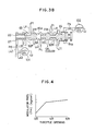
- the shift valve 80 takes the third position as shown in Figure 3B.
- control valve 90 controls the torque converter pressure in accordance with the duty ratio of the duty solenoid valve 101 and the throttle modulator pressure Pm of the throttle modulator line L3.
- the spool 95 is subjected to a rightward force due to the resilient force of the spring 99, throttle modulator pressure Pm at a left land portion and subjected to a line pressure of the line L14 separated from the line L13 through an orifice at a stepped portion 95c formed on a middle portion of the left land portion thereof. This is effected to suppress a fluctuation of the torque converter pressure Pr on the R-chamber 65 and the line pressure Pf on the F-chamber 64.
- Figure 4 shows a relationship between the throttle opening and the throttle modulator pressure Pm.
- Figure 5 shows a relationship between the duty ratio of the duty solenoid valve and the duty pressure Pd, and
- Figure 6 shows a relationship of the throttle opening, the duty ratio, the pressure difference between the line pressures Pr and Pf.
- the throttle modulator pressure Pm is increased as the throttle opening is increased.
- the duty pressure Pd is reduced due to the increase of the duty ratio.
- the control valve 90 is controlled based on the duty pressure Pd and the throttle modulator pressure Pm for an improved and responsive control of the pressure of R and F-chambers 65 and 64.
- the line pressure Pf which determines the F-chamber 64 is controlled based on the control valve 90 when the shift valve 80 is set at the third position for establishing the slip condition of the lock-up clutch 26.
- the torque converter pressure in the line L11 is introduced to the line LR to constitute the line pressure Pr which determines the pressure in the R-chamber 65 so that the pressure difference dP between the line pressures Pr and Pf can be controlled by the control valve 90 based on the pressure difference between the duty pressure Pd and the throttle modulator pressure Pm.
- the duty solenoid valve 101 which controls the duty pressure Pd is controlled by means of a feedback control so as to reduce a speed difference between the engine and the turbine 23 within a certain level.
- the throttle modulator pressure Pm is increased as the throttle opening is increased.
- the spool 95 is moved due to the increase of the throttle opening to reduce the line pressure Pf so that the pressure in the F-chamber 64 is reduced to displace the lock-up clutch 26 toward the disengaged condition.
- the duty pressure Pd and the throttle modulator pressure Pm are controlled independently from each other so that the pressure difference Pd can be widely controlled.
- the control valve 90 is controlled based on not only the speed difference for the feedback control but also the throttle opening. This makes the slip control responsive.
- the control valve 90 intervenes the line L15 and the line L14 so that a pressure fluctuation can be reduced during the slip control of the lock-up clutch 26.
- the three different conditions of the lock-up clutch 26 can be readily established by switching the positions of the single shift valve 80.
- the engaging force of the lock-up clutch can be smoothly controlled through a control for the control valve 90.
Landscapes
- Engineering & Computer Science (AREA)
- General Engineering & Computer Science (AREA)
- Mechanical Engineering (AREA)
- Control Of Fluid Gearings (AREA)
Applications Claiming Priority (2)
| Application Number | Priority Date | Filing Date | Title |
|---|---|---|---|
| JP275894/88 | 1988-10-31 | ||
| JP63275894A JPH0745906B2 (ja) | 1988-10-31 | 1988-10-31 | 流体継手のスリップ制御装置 |
Publications (3)
| Publication Number | Publication Date |
|---|---|
| EP0367551A2 true EP0367551A2 (fr) | 1990-05-09 |
| EP0367551A3 EP0367551A3 (fr) | 1991-03-27 |
| EP0367551B1 EP0367551B1 (fr) | 1994-08-31 |
Family
ID=17561922
Family Applications (1)
| Application Number | Title | Priority Date | Filing Date |
|---|---|---|---|
| EP89311216A Expired - Lifetime EP0367551B1 (fr) | 1988-10-31 | 1989-10-31 | Système de commande pour convertisseur de couple d'une transmission automatique |
Country Status (4)
| Country | Link |
|---|---|
| US (1) | US4989702A (fr) |
| EP (1) | EP0367551B1 (fr) |
| JP (1) | JPH0745906B2 (fr) |
| DE (1) | DE68917860T2 (fr) |
Cited By (4)
| Publication number | Priority date | Publication date | Assignee | Title |
|---|---|---|---|---|
| EP0452887A2 (fr) * | 1990-04-18 | 1991-10-23 | Mazda Motor Corporation | Système de commande pour un convertisseur de couple |
| EP0537818A1 (fr) * | 1991-10-15 | 1993-04-21 | General Motors Corporation | Système de commande hydraulique pour transmissions automatiques |
| EP0814285A2 (fr) * | 1996-06-07 | 1997-12-29 | Ford Motor Company Limited | Transmission automatique à plusiers vitesses et convertisseur de couple pontable |
| US6231480B1 (en) * | 1997-05-12 | 2001-05-15 | Mazda Motor Corporation | Lockup control system for fluid coupling of automatic transmission |
Families Citing this family (19)
| Publication number | Priority date | Publication date | Assignee | Title |
|---|---|---|---|---|
| JP2825289B2 (ja) * | 1989-10-16 | 1998-11-18 | マツダ株式会社 | 流体継手のスリップ制御装置 |
| DE3938724C2 (de) * | 1989-11-23 | 1998-04-30 | Mannesmann Sachs Ag | Hydrodynamischer Drehmomentwandler mit Überbrückungskupplung |
| JP2621649B2 (ja) * | 1990-11-26 | 1997-06-18 | 日産自動車株式会社 | ロックアップクラッチ制御装置 |
| US5214984A (en) * | 1990-12-06 | 1993-06-01 | Jatco Corporation | Pressure control system for automotive automatic power transmission with feature of fluid pressure dependent actuator control |
| US5383379A (en) * | 1991-06-07 | 1995-01-24 | Honda Giken Kogyo Kabushiki Kaisha | Hydraulic pressure control for automatic transmission |
| DE4121586C2 (de) * | 1991-06-29 | 2001-06-21 | Mannesmann Sachs Ag | Hydrodynamischer Drehmomentwandler mit Kühlölkreislauf |
| JP3076439B2 (ja) * | 1992-01-28 | 2000-08-14 | ジヤトコ・トランステクノロジー株式会社 | ロックアップクラッチの制御装置 |
| US5233890A (en) * | 1992-03-31 | 1993-08-10 | Saturn Corporation | Transmission torque converter clutch disable control |
| US5251734A (en) * | 1992-05-08 | 1993-10-12 | Chrysler Corporation | Hydraulic controls for lock-up clutch of a torque converter assembly |
| US5372226A (en) * | 1993-06-24 | 1994-12-13 | Ford Motor Company | System for preventing inadvertent application of torque converter lock-up clutch |
| EP0684910B1 (fr) * | 1993-12-29 | 1999-03-31 | Hyundai Motor Company | Systeme de commande hydraulique pour transmission automatique |
| US5701982A (en) * | 1994-07-11 | 1997-12-30 | Nippondenso Co., Ltd. | Lockup control system for automatic transmission |
| US5531302A (en) * | 1994-09-02 | 1996-07-02 | General Motors Corporation | Controlled capacity torque converter clutch lock-up transition control |
| JP2928734B2 (ja) * | 1994-10-31 | 1999-08-03 | 本田技研工業株式会社 | 車両用クラッチ機構の作動状態判定装置 |
| JP3644996B2 (ja) * | 1995-01-31 | 2005-05-11 | 本田技研工業株式会社 | 油圧作動式変速機の制御装置 |
| US6990996B2 (en) * | 2002-04-29 | 2006-01-31 | Sonnax Industries, Inc. | Torque converter clutch regulator valve assembly and method of installation |
| US7104273B1 (en) | 2003-04-28 | 2006-09-12 | Sonnax Industries, Inc. | Torque converter clutch regulator valve assembly and method of installation |
| JP4054778B2 (ja) * | 2004-03-31 | 2008-03-05 | ジヤトコ株式会社 | 自動変速機の制御装置 |
| DE102008000679A1 (de) * | 2008-03-14 | 2009-09-17 | Zf Friedrichshafen Ag | Hydraulische Steuerungsanordnung zum Steuern eines variablen Fluidvolumenstroms |
Citations (3)
| Publication number | Priority date | Publication date | Assignee | Title |
|---|---|---|---|---|
| US3985046A (en) * | 1975-06-23 | 1976-10-12 | Caterpillar Tractor Co. | Control valve for a torque converter lock-up clutch or the like |
| US4468988A (en) * | 1980-08-04 | 1984-09-04 | Mitsubishi Jidosha Kogyo Kabushiki Kaisha | Slip control system for a clutch |
| US4706790A (en) * | 1986-07-17 | 1987-11-17 | General Motors Corporation | Gain scheduling technique for a closed loop slip control system |
Family Cites Families (13)
| Publication number | Priority date | Publication date | Assignee | Title |
|---|---|---|---|---|
| DE3050078A1 (en) * | 1979-11-29 | 1982-03-18 | Nissan Motor | Hydraulic control type automatic transmission |
| JPS5733253A (en) * | 1980-08-04 | 1982-02-23 | Mitsubishi Motors Corp | Torque transmitter |
| JPS5999158A (ja) * | 1982-11-30 | 1984-06-07 | Aisin Warner Ltd | 車両用無段自動変速機の流体継手用ロツクアツプクラツチ制御機構 |
| JPS59137658A (ja) * | 1983-01-27 | 1984-08-07 | Mazda Motor Corp | 自動変速機のロツクアツプ制御装置 |
| JPS59187161A (ja) * | 1983-03-24 | 1984-10-24 | Mazda Motor Corp | 自動変速機のロツクアツプ制御装置 |
| JPS59219567A (ja) * | 1983-05-27 | 1984-12-10 | Mazda Motor Corp | 自動変速機のロツクアツプ制御装置 |
| JPS6084464A (ja) * | 1983-10-14 | 1985-05-13 | Nissan Motor Co Ltd | 自動変速機の油圧制御装置 |
| JPS6084465A (ja) * | 1983-10-17 | 1985-05-13 | Honda Motor Co Ltd | 車両用自動変速機における流体伝動装置の直結制御装置 |
| JPH0621649B2 (ja) * | 1983-12-30 | 1994-03-23 | アイシン・エィ・ダブリュ株式会社 | 車両用自動変速機の流体継手のロツクアツプクラツチ制御装置 |
| US4660693A (en) * | 1984-04-04 | 1987-04-28 | Toyota Jidosha Kabushiki Kaisha | Hydraulic pressure control apparatus for use in automatic transmission |
| JPS6198627A (ja) * | 1984-10-17 | 1986-05-16 | Mazda Motor Corp | 自動車のパワ−ユニツト |
| JPS61206868A (ja) * | 1985-03-11 | 1986-09-13 | Nissan Motor Co Ltd | トルクコンバ−タのスリツプ制御装置 |
| JPS62297567A (ja) * | 1986-06-16 | 1987-12-24 | Honda Motor Co Ltd | 車両用変速機における流体トルクコンバ−タ用クラツチの作動制御方法 |
-
1988
- 1988-10-31 JP JP63275894A patent/JPH0745906B2/ja not_active Expired - Fee Related
-
1989
- 1989-10-30 US US07/428,763 patent/US4989702A/en not_active Expired - Fee Related
- 1989-10-31 EP EP89311216A patent/EP0367551B1/fr not_active Expired - Lifetime
- 1989-10-31 DE DE68917860T patent/DE68917860T2/de not_active Expired - Fee Related
Patent Citations (3)
| Publication number | Priority date | Publication date | Assignee | Title |
|---|---|---|---|---|
| US3985046A (en) * | 1975-06-23 | 1976-10-12 | Caterpillar Tractor Co. | Control valve for a torque converter lock-up clutch or the like |
| US4468988A (en) * | 1980-08-04 | 1984-09-04 | Mitsubishi Jidosha Kogyo Kabushiki Kaisha | Slip control system for a clutch |
| US4706790A (en) * | 1986-07-17 | 1987-11-17 | General Motors Corporation | Gain scheduling technique for a closed loop slip control system |
Cited By (7)
| Publication number | Priority date | Publication date | Assignee | Title |
|---|---|---|---|---|
| EP0452887A2 (fr) * | 1990-04-18 | 1991-10-23 | Mazda Motor Corporation | Système de commande pour un convertisseur de couple |
| EP0452887A3 (en) * | 1990-04-18 | 1992-01-29 | Mazda Motor Corporation | Control system for torque converter |
| US5339935A (en) * | 1990-04-18 | 1994-08-23 | Mazda Motor Corporation | Control system for torque converter |
| EP0537818A1 (fr) * | 1991-10-15 | 1993-04-21 | General Motors Corporation | Système de commande hydraulique pour transmissions automatiques |
| EP0814285A2 (fr) * | 1996-06-07 | 1997-12-29 | Ford Motor Company Limited | Transmission automatique à plusiers vitesses et convertisseur de couple pontable |
| EP0814285A3 (fr) * | 1996-06-07 | 1999-12-08 | Ford Motor Company Limited | Transmission automatique à plusiers vitesses et convertisseur de couple pontable |
| US6231480B1 (en) * | 1997-05-12 | 2001-05-15 | Mazda Motor Corporation | Lockup control system for fluid coupling of automatic transmission |
Also Published As
| Publication number | Publication date |
|---|---|
| DE68917860D1 (de) | 1994-10-06 |
| DE68917860T2 (de) | 1995-04-27 |
| US4989702A (en) | 1991-02-05 |
| EP0367551A3 (fr) | 1991-03-27 |
| JPH0745906B2 (ja) | 1995-05-17 |
| JPH02120568A (ja) | 1990-05-08 |
| EP0367551B1 (fr) | 1994-08-31 |
Similar Documents
| Publication | Publication Date | Title |
|---|---|---|
| EP0367551B1 (fr) | Système de commande pour convertisseur de couple d'une transmission automatique | |
| JP2748298B2 (ja) | 自動変速機の油圧制御装置 | |
| US4270636A (en) | Lock-up control system for a torque converter including a timing arrangement | |
| US4476747A (en) | Timing control valve in automatic transmission control apparatus | |
| US6835147B2 (en) | Hydraulic pressure controller for automatic transmission | |
| US5339935A (en) | Control system for torque converter | |
| US4722251A (en) | Hydraulic circuit for controlling an automatic transmission | |
| US4995285A (en) | Fail-safe hydraulic control valves in an automatic transmission | |
| US4474084A (en) | Shift device of hydraulic control system for automatic transmission | |
| US4462280A (en) | Manual valve for hydraulic control system for automatic transmission | |
| JP2892056B2 (ja) | 自動変速機 | |
| JP3186760B2 (ja) | 自動変速機の油圧制御回路 | |
| US5651751A (en) | Shift control system of an automatic transmission used in a vehicle | |
| JP3076446B2 (ja) | 自動変速機の制御装置 | |
| US5409427A (en) | Automatic transmission control system | |
| US4903550A (en) | Hydraulic control device for automatic transmission | |
| EP0725239A2 (fr) | Dispositif de commande pour une transmission de véhicule actionnée hydrauliquement | |
| US5038638A (en) | Hydraulic control device for an automatic transmission | |
| US5842951A (en) | Speed change control system for automatic transmission | |
| EP0791767B1 (fr) | Dispositif de commande hydraulique pour transmission de véhicule | |
| US4565267A (en) | Direct-coupling clutch control device for a torque converter in vehicular automatic transmission | |
| JP2917272B2 (ja) | 車両用自動変速機の油圧制御装置 | |
| US4779492A (en) | Twin type hydraulic pressure control device with individual line pressure regulation valves for two stage automatic transmission | |
| JPH09177959A (ja) | 自動変速機の制御装置 | |
| JP3516525B2 (ja) | 自動変速機の油圧制御装置 |
Legal Events
| Date | Code | Title | Description |
|---|---|---|---|
| PUAI | Public reference made under article 153(3) epc to a published international application that has entered the european phase |
Free format text: ORIGINAL CODE: 0009012 |
|
| AK | Designated contracting states |
Kind code of ref document: A2 Designated state(s): DE FR GB |
|
| PUAL | Search report despatched |
Free format text: ORIGINAL CODE: 0009013 |
|
| AK | Designated contracting states |
Kind code of ref document: A3 Designated state(s): DE FR GB |
|
| 17P | Request for examination filed |
Effective date: 19910920 |
|
| 17Q | First examination report despatched |
Effective date: 19930325 |
|
| GRAA | (expected) grant |
Free format text: ORIGINAL CODE: 0009210 |
|
| AK | Designated contracting states |
Kind code of ref document: B1 Designated state(s): DE FR GB |
|
| REF | Corresponds to: |
Ref document number: 68917860 Country of ref document: DE Date of ref document: 19941006 |
|
| ET | Fr: translation filed | ||
| PLBE | No opposition filed within time limit |
Free format text: ORIGINAL CODE: 0009261 |
|
| STAA | Information on the status of an ep patent application or granted ep patent |
Free format text: STATUS: NO OPPOSITION FILED WITHIN TIME LIMIT |
|
| 26N | No opposition filed | ||
| PGFP | Annual fee paid to national office [announced via postgrant information from national office to epo] |
Ref country code: FR Payment date: 19961009 Year of fee payment: 8 |
|
| PGFP | Annual fee paid to national office [announced via postgrant information from national office to epo] |
Ref country code: GB Payment date: 19961022 Year of fee payment: 8 |
|
| PG25 | Lapsed in a contracting state [announced via postgrant information from national office to epo] |
Ref country code: GB Free format text: LAPSE BECAUSE OF NON-PAYMENT OF DUE FEES Effective date: 19971031 Ref country code: FR Free format text: THE PATENT HAS BEEN ANNULLED BY A DECISION OF A NATIONAL AUTHORITY Effective date: 19971031 |
|
| GBPC | Gb: european patent ceased through non-payment of renewal fee |
Effective date: 19971031 |
|
| REG | Reference to a national code |
Ref country code: FR Ref legal event code: ST |
|
| PGFP | Annual fee paid to national office [announced via postgrant information from national office to epo] |
Ref country code: DE Payment date: 20061026 Year of fee payment: 18 |
|
| PG25 | Lapsed in a contracting state [announced via postgrant information from national office to epo] |
Ref country code: DE Free format text: LAPSE BECAUSE OF NON-PAYMENT OF DUE FEES Effective date: 20080501 |