EP0361753B1 - Mécanisme de détection d'absence de papier et de position de départ - Google Patents
Mécanisme de détection d'absence de papier et de position de départ Download PDFInfo
- Publication number
- EP0361753B1 EP0361753B1 EP89309483A EP89309483A EP0361753B1 EP 0361753 B1 EP0361753 B1 EP 0361753B1 EP 89309483 A EP89309483 A EP 89309483A EP 89309483 A EP89309483 A EP 89309483A EP 0361753 B1 EP0361753 B1 EP 0361753B1
- Authority
- EP
- European Patent Office
- Prior art keywords
- paper
- lever
- carriage
- printer
- groove
- Prior art date
- Legal status (The legal status is an assumption and is not a legal conclusion. Google has not performed a legal analysis and makes no representation as to the accuracy of the status listed.)
- Expired - Lifetime
Links
Images


Classifications
-
- B—PERFORMING OPERATIONS; TRANSPORTING
- B41—PRINTING; LINING MACHINES; TYPEWRITERS; STAMPS
- B41J—TYPEWRITERS; SELECTIVE PRINTING MECHANISMS, i.e. MECHANISMS PRINTING OTHERWISE THAN FROM A FORME; CORRECTION OF TYPOGRAPHICAL ERRORS
- B41J29/00—Details of, or accessories for, typewriters or selective printing mechanisms not otherwise provided for
- B41J29/46—Applications of alarms, e.g. responsive to approach of end of line
- B41J29/48—Applications of alarms, e.g. responsive to approach of end of line responsive to breakage or exhaustion of paper or approach of bottom of paper
Definitions
- This invention relates to printers, and more particularly to printers having a mechanism for detecting a paper-out condition and a column zero position.
- Optical devices have also been used to detect a paper-out condition. These optical devices ordinarily are equipped with a light emitting diode (LED) to shine on the paper and a photo transistor to receive the light reflected from the paper. These optical devices are very sensitive to ambient light levels and therefore must be shielded from any outside light source, but still must be open to the extent that the light is permitted to shine on the paper and reflect back. They are also susceptible to debris dropping from the paper or from the printer mechanism, which debris may obscure the light path.
- LED light emitting diode
- end position of the carriage has been detected by simple electromechanial switches which are very sensitive and difficult to adjust. They also tend to be rather short lived.
- Optical reflection devices as mentioned above have also been used for detecting the end position of the carriage.
- a pad associated with the carriage or the head has been used to interrupt a light beam between an LED and a photo transistor.
- a printer having a lever for detecting a paper out condition.
- the lever has one end biassed against the paper on a platen and when the paper runs out the end moves into a groove in the platen. As that happens the other end of the lever moves to block the path between a light emitter and receiver thereby providing an indication of the paper out condition.
- a lever attached to the carriage contacts the detection lever arm, moving it from its normal state and causing the LED to transmit light to the photo transistor.
- a printer for printing characters on paper comprising a platen having a groove, a carriage supporting a printhead that traverses the paper which is supported by the platen and covers the groove and a detection mechanism comprising a pivoted lever having an end which in a normal state is pressed against the part of the paper covering the groove, and another part for selectively blocking light communication between a light emitting means and a light detecting means, the detection mechanism indicating a paper-out condition by the end of the lever moving into the groove so as to change the position of the other part of the lever relative to the light communication path, characterised in that the end of the lever is pressed against the paper by a spring, in that in the normal state the other part of the lever blocks light communication between the emitting and detecting means and in the paper-out condition the other part of the lever does not block light communication between the emitting and receiving means, and in that the carriage has associated with it a contacting means positioned to contact and move the lever out of its normal state to allow light communication between the emitting and receiving means, and in that
- a printer for printing characters on paper employs a mechanism to detect a paper-out condition and column zero position.
- This mechanism uses a detection lever arm which is spring loaded and passes through a high resolution optical sensor.
- the optical sensor includes an LED that emits light to a photo transistor. In the normal operating position, the detection lever arm blocks the sensor beam.
- the printer platen which supports the paper, has a groove formed therein.
- the groove is dimensioned to receive the upper end of the detection lever arm when there is no paper covering the platen and the groove.
- the upper end moves into the groove due to the force exerted by the spring.
- the lower end of the detection lever arm which in its normal position, blocks the sensor beam, moves out and the optical transistor receives light from the LED, providing a signal indicating that there is a paper-out condition.
- the printhead (thermal in this preferred embodiment) is mounted on a carriage which traverses the width of the paper for printing in one or both directions.
- An activation arm is attached to the carriage so that when the carriage is moved to the extreme left position, the activation arm engages the detection lever arm, pushing the lower end out of its normal position so that the optical transistor receives light from the LED, providing a signal indicative of the column zero position.
- the principal object of this invention is to provide a printer having a mechanism for detecting both a paper-out condition and a column zero position.
- Another object of this invention is to provide an optical sensor for a paper-out detector that relies on direct communication between an LED and a photo transistor without need for reflection.
- Still another object of this invention is to provide a printer with a detection mechanism for a paper-out condition and a column zero position that is not sensitive to debris, adjustment and paper thickness.
- Figure 1 is a perspective drawing of a portable terminal which incorporates the printer of this invention.
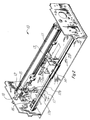
- Figure 2 is a cutaway perspective of the printer of this invention.
- Figures 3a and 3b are cutaway front views illustrating a paper-in and a paper-out condition, respectively.
- Figure 4 is a cutaway front view illustrating a column zero position.
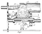
- Figure 5 is a cutaway front view illustrating a paper-out condition about to be changed to a column zero position.
- Figure 6 is a schematic diagram of the generation of the paper-out and column zero signal.
- the printer of this invention has a common mechanism for detecting both paper-out condition and a column zero position in a novel manner. For an understanding of the mechanism, turn first to Figure 1.
- FIG. 1 illustrates portable terminal 1 which incorporates printer 10.
- printer 10 is a thermal printer but an ink jet printer also is alternatively employed.
- the printer could be a wire matrix printer or any other type printer, with a movable carriage for printing on paper.
- FIG 2 is a cutaway perspective of printer 10 illustrating platen 11 having groove 12 formed therein.
- Carriage 14 is shown riding on guide rod 23 and having activation arm 13 attached.
- Carriage 14 carries printhead 22 (see Fig. 5).
- Activation arm 13 is positioned and intended to strike activation lever arm 16 when carriage 14 moves to the left.
- Activation lever arm 16 rotates about pivot point 18.
- Torsion spring 15 bears against the upper end of detection lever arm 16 and the lower end of lever arm 16, as shown in the normal state, blocks light from LED 17a from passing to photo transistor 17b, both of optical sensor 17.
- Figure 3a is a sectional front view illustrating detection lever arm 16 in its normal state with its lower end 16b positioned within optical sensor 17 and with its upper end 16a urged, by spring 15, against paper 21. Paper 21 is shown riding on platen 11, over groove 12.
- Figure 3b illustrates platen 11 with no paper 21 in place.
- spring 15 has urged the upper end 16a of detection lever arm 16 into groove 12, moving lower end 16b out of optical sensor 17, thereby enabling a light path between LED 17a and photo transistor 17b, providing a signal, indicating a paper-out condition.
- Figure 4 is a cutaway front view illustrating the column zero position. Detection lever arm 16 is shown with lower end 16b having been moved away from optical sensor 17, pivoted at point 18. Note that detection lever arm 16 is moved in the opposite direction from the paper-out condition.
- Figure 5 is a cutaway front section showing detection lever arm 16 in the paper-out position but with activation arm 13 contacting detection lever arm 16 as carriage 14 carrying printhead 22 moves to the left. As the motion of carriage 14 continues, activation arm 13 pushes detection lever arm 16 to the left side of optical sensor 17 as indicated in Figure 4.
- Figure 6 schematically illustrates LED 17a in association with photo transistor 17b within optical sensor 17.
- the collector of photo transistor 17b passes signal PO/COL0 through terminals EB and EA, ultimately to AND gate 25, forcing the interrupt signal to be sent to a microprocessor which is part of printer 10.
- the PO/COL0 signal is sent through buffer 26 to identify the interrupt.
- FIG. 3a paper 21 is shown covering platen 11 and also covering groove 12, formed in platen 11.
- FIG 4 illustrates detection lever arm 16 in the column zero position having had lower end 16b pivoted on pivot 18 to the left of optical sensor 17.
- a PO/COL0 signal is again sent, generating an interrupt to the microprocessor through AND gate 25.
- Column zero is not an ordinary, operational condition. Column zero occurs only upon starting or resetting of the system. Otherwise, during normal operation, column zero cannot occur because the system always return to column one, under control of the microprocessor. Therefore, if signal PO/COL0 occurs during normal operation, it must signify a paper-out condition. The operation of the microprocessor is not part of this invention and will not be described herein.
- Figure 5 illustrates a condition where paper-out has been detected as shown by the position of detection lever arm 16.
- activation arm 13 is shown contacting lever arm 16, and as carriage 14 proceeds on guide 23 to the left, lever arm 16 will be moved to the left indicating a column zero position.
Claims (4)
- Imprimante (10) pour l'impression de caractères sur du papier (21) comprenant un cylindre d'impression (11) présentant une rainure (12), un chariot (14) supportant une tête d'impression (22) qui vient en contact avec le papier (21) qui est supporté par le rouleau d'impression (11) et couvre la rainure (12) et un mécanisme de détection comprenant un levier pivotant (16) qui comporte une extrémité (16A) qui, à l'état normal, est pressée contre la partie du papier recouvrant la rainure (12) et une autre partie (16B) destinée à bloquer de manière sélective la communication lumineuse entre un organe émetteur de lumière (17A) et un organe détecteur de lumière (17B), le mécanisme de détection indiquant une condition d'absence de papier grâce à l'extrémité (16A) du levier (16) venant se placer dans la rainure (12) de manière à changer la position de l'autre partie du levier par rapport au trajet de communication lumineuse, caractérisée en ce que
l'extrémité (16A) du levier est pressée contre le papier (21) par un ressort,
en ce que,
dans l'état normal, l'autre partie (16B) du levier (16) bloque la communication lumineuse entre l'organe émetteur et l'organe détecteur (17A,17B) et, dans la condition d'absence de papier, l'autre partie (16B) du levier (16) ne bloque pas la communication lumineuse entre l'organe émetteur et l'organe récepteur (17A,17B)
et en ce que
le chariot comporte, un organe de contact qui lui est associé et qui est positionné pour venir en contact et déplacer le levier (16) hors de son état normal pour permettre la communication lumineuse entre l'organe émetteur et l'organe détecteur (17A,17B) indiquant de ce fait une position de départ de la tête d'impression (22). - Imprimante selon la revendication 1, dans laquelle l'organe de contact comprend un bras d'actionnement (13) fixé au chariot (14) et positionné pour appuyer sur le levier (16) lorsque le chariot se déplace vers la position terminale gauche, ce qui force l'autre partie (16B) à sortir de l'état normal dans un état de communication lumineuse, de manière à indiquer une position de départ.
- Imprimante selon la revendication 1 ou 2, dans laquelle l'axe de rotation du levier (16) est perpendiculaire à la direction de déplacement du chariot (14).
- Imprimante selon la revendication 1,2 ou 3, dans laquelle le ressort est un ressort spiral monté avec son axe parallèle à l'axe de rotation du levier.
Applications Claiming Priority (2)
| Application Number | Priority Date | Filing Date | Title |
|---|---|---|---|
| US07/251,435 US4881840A (en) | 1988-09-30 | 1988-09-30 | Printer having paper-out and column zero detection mechanism |
| US251435 | 1994-05-31 |
Publications (3)
| Publication Number | Publication Date |
|---|---|
| EP0361753A2 EP0361753A2 (fr) | 1990-04-04 |
| EP0361753A3 EP0361753A3 (en) | 1990-10-24 |
| EP0361753B1 true EP0361753B1 (fr) | 1994-05-04 |
Family
ID=22951960
Family Applications (1)
| Application Number | Title | Priority Date | Filing Date |
|---|---|---|---|
| EP89309483A Expired - Lifetime EP0361753B1 (fr) | 1988-09-30 | 1989-09-19 | Mécanisme de détection d'absence de papier et de position de départ |
Country Status (4)
| Country | Link |
|---|---|
| US (1) | US4881840A (fr) |
| EP (1) | EP0361753B1 (fr) |
| JP (1) | JP2860120B2 (fr) |
| DE (1) | DE68915096T2 (fr) |
Families Citing this family (15)
| Publication number | Priority date | Publication date | Assignee | Title |
|---|---|---|---|---|
| US5158221A (en) * | 1988-05-24 | 1992-10-27 | Ricoh Company, Ltd. | Automatic document feeder capable of feeding a document in the form of a computer form |
| DE3934398A1 (de) * | 1989-10-11 | 1991-04-25 | Mannesmann Ag | Einrichtung zum ausloesen eines kipphebels, mittels dessen kipphebelarmen jeweils ein gebersignal erzeugbar ist, insbesondere zum abtasten blattfoermiger aufzeichnungstraeger in belegverarbeitungsgeraeten |
| JP2717138B2 (ja) * | 1990-09-12 | 1998-02-18 | セイコープレシジョン株式会社 | センサによる設定方法 |
| US5746521A (en) * | 1996-12-20 | 1998-05-05 | Intermec Corporation | Thermal printhead with integrated printhead position sensor |
| JP4686843B2 (ja) * | 1999-12-06 | 2011-05-25 | セイコーエプソン株式会社 | 記録装置用の検出装置、及び、これを備えた記録装置 |
| JP2002273911A (ja) | 2001-03-15 | 2002-09-25 | Seiko Epson Corp | インクジェットプリンタ |
| US7228965B2 (en) * | 2004-09-25 | 2007-06-12 | International Paper Company | Integrated appliance container for support during assembly transport and display |
| JP5440214B2 (ja) * | 2010-01-29 | 2014-03-12 | セイコーエプソン株式会社 | シート材検知装置及び記録装置 |
| JP5520731B2 (ja) * | 2010-07-27 | 2014-06-11 | 株式会社沖データ | 媒体検知装置及び画像形成装置 |
| JP2013249186A (ja) * | 2012-06-04 | 2013-12-12 | Seiko Epson Corp | 記録装置、及び、記録装置における検出構造 |
| GB2515993B (en) * | 2013-04-08 | 2016-04-27 | Innovative Tech Ltd | A banknote and voucher handling apparatus |
| US9509877B1 (en) | 2015-06-25 | 2016-11-29 | Hewlett-Packard Development Company, L.P. | Indication of whether print job is a cut media or continuous media print job |
| CN111565935B (zh) | 2018-01-18 | 2021-12-10 | 惠普发展公司,有限责任合伙企业 | 具有传感器的打印机滑架 |
| CN112319065B (zh) * | 2018-10-26 | 2022-05-27 | 深圳市汉森软件有限公司 | 喷墨打印机小车防撞方法、装置及计算机可读存储介质 |
| CN111550982B (zh) * | 2020-04-21 | 2021-12-17 | 宁夏共享机床辅机有限公司 | 物料检测装置与带有该装置的微波烘干设备 |
Family Cites Families (7)
| Publication number | Priority date | Publication date | Assignee | Title |
|---|---|---|---|---|
| US2293283A (en) * | 1940-03-14 | 1942-08-18 | Dow Raymond | Typewriter attachment |
| US2320110A (en) * | 1941-04-29 | 1943-05-25 | George A Walker | Electric indicator for typewriters |
| JPS5625488A (en) * | 1979-08-09 | 1981-03-11 | Canon Inc | Printer |
| JPS5787983A (en) * | 1980-11-21 | 1982-06-01 | Toshiba Corp | Typing machine |
| JPS5845987A (ja) * | 1981-09-16 | 1983-03-17 | Seikosha Co Ltd | ドツトプリンタの印字開始位置決定方法 |
| JPS61102280A (ja) * | 1984-10-25 | 1986-05-20 | Oki Electric Ind Co Ltd | プリンタの印字媒体検出機構 |
| US4800402A (en) * | 1988-01-07 | 1989-01-24 | Calcomp Inc. | Plotter paper sizing system |
-
1988
- 1988-09-30 US US07/251,435 patent/US4881840A/en not_active Expired - Lifetime
-
1989
- 1989-09-19 EP EP89309483A patent/EP0361753B1/fr not_active Expired - Lifetime
- 1989-09-19 DE DE68915096T patent/DE68915096T2/de not_active Expired - Fee Related
- 1989-09-29 JP JP1255102A patent/JP2860120B2/ja not_active Expired - Fee Related
Also Published As
| Publication number | Publication date |
|---|---|
| DE68915096D1 (de) | 1994-06-09 |
| DE68915096T2 (de) | 1994-08-18 |
| EP0361753A3 (en) | 1990-10-24 |
| JPH02212182A (ja) | 1990-08-23 |
| US4881840A (en) | 1989-11-21 |
| JP2860120B2 (ja) | 1999-02-24 |
| EP0361753A2 (fr) | 1990-04-04 |
Similar Documents
| Publication | Publication Date | Title |
|---|---|---|
| EP0361753B1 (fr) | Mécanisme de détection d'absence de papier et de position de départ | |
| US4793605A (en) | Paper detector of printer | |
| US7549814B1 (en) | Compact low paper sensor mechanism | |
| EP0574332A2 (fr) | Imprimante thermique avec un capteur sans contact pour déterminer le type de support | |
| US6386676B1 (en) | Reflective type media sensing methodology | |
| EP0900754B1 (fr) | Dispositif optique de détection des supports d'impression dans des imprimantes | |
| US4897670A (en) | Thermal transfer printer | |
| US5139351A (en) | Thermal recording apparatus having a movable platen roller | |
| US6599041B1 (en) | Sheet movement sensor | |
| US5082384A (en) | Paper detecting apparatus for printer | |
| US7777174B2 (en) | Image forming apparatus including a recording medium detector with a light shield | |
| US4859099A (en) | Automatic paper loading apparatus for printer having paper bail actuating device | |
| JP2007535738A (ja) | 自動車用の操作要素 | |
| US4793723A (en) | Mechanism for detecting end of ink ribbon in a ribbon cassette | |
| JP2694884B2 (ja) | プリンタ | |
| US4639607A (en) | Device for sensing a recording medium in a line printer | |
| JP2002264355A (ja) | 液面検知装置およびインクジェットプリンタ | |
| JP4338301B2 (ja) | プリンタ | |
| US4030589A (en) | Data processing machine | |
| JPH03275A (ja) | プリンタ | |
| US6073928A (en) | Sheet end detecting mechanism | |
| JPH08217326A (ja) | 印字装置における用紙検知装置 | |
| JPH03197162A (ja) | シリアルプリンタ | |
| JPH05149721A (ja) | プリンタ用ギヤツプセンサ | |
| JP3228329B2 (ja) | ホームポジションにおけるキャリッジの検知装置 |
Legal Events
| Date | Code | Title | Description |
|---|---|---|---|
| PUAI | Public reference made under article 153(3) epc to a published international application that has entered the european phase |
Free format text: ORIGINAL CODE: 0009012 |
|
| AK | Designated contracting states |
Kind code of ref document: A2 Designated state(s): DE FR GB IT |
|
| PUAL | Search report despatched |
Free format text: ORIGINAL CODE: 0009013 |
|
| AK | Designated contracting states |
Kind code of ref document: A3 Designated state(s): DE FR GB IT |
|
| 17P | Request for examination filed |
Effective date: 19910417 |
|
| 17Q | First examination report despatched |
Effective date: 19921116 |
|
| GRAA | (expected) grant |
Free format text: ORIGINAL CODE: 0009210 |
|
| ITF | It: translation for a ep patent filed |
Owner name: BARZANO' E ZANARDO ROMA S.P.A. |
|
| AK | Designated contracting states |
Kind code of ref document: B1 Designated state(s): DE FR GB IT |
|
| REF | Corresponds to: |
Ref document number: 68915096 Country of ref document: DE Date of ref document: 19940609 |
|
| ET | Fr: translation filed | ||
| PLBE | No opposition filed within time limit |
Free format text: ORIGINAL CODE: 0009261 |
|
| STAA | Information on the status of an ep patent application or granted ep patent |
Free format text: STATUS: NO OPPOSITION FILED WITHIN TIME LIMIT |
|
| 26N | No opposition filed | ||
| REG | Reference to a national code |
Ref country code: GB Ref legal event code: IF02 |
|
| PGFP | Annual fee paid to national office [announced via postgrant information from national office to epo] |
Ref country code: GB Payment date: 20060804 Year of fee payment: 18 |
|
| PGFP | Annual fee paid to national office [announced via postgrant information from national office to epo] |
Ref country code: FR Payment date: 20060906 Year of fee payment: 18 |
|
| PGFP | Annual fee paid to national office [announced via postgrant information from national office to epo] |
Ref country code: DE Payment date: 20060929 Year of fee payment: 18 |
|
| PGFP | Annual fee paid to national office [announced via postgrant information from national office to epo] |
Ref country code: IT Payment date: 20060930 Year of fee payment: 18 |
|
| GBPC | Gb: european patent ceased through non-payment of renewal fee |
Effective date: 20070919 |
|
| PG25 | Lapsed in a contracting state [announced via postgrant information from national office to epo] |
Ref country code: DE Free format text: LAPSE BECAUSE OF NON-PAYMENT OF DUE FEES Effective date: 20080401 |
|
| REG | Reference to a national code |
Ref country code: FR Ref legal event code: ST Effective date: 20080531 |
|
| PG25 | Lapsed in a contracting state [announced via postgrant information from national office to epo] |
Ref country code: FR Free format text: LAPSE BECAUSE OF NON-PAYMENT OF DUE FEES Effective date: 20071001 |
|
| PG25 | Lapsed in a contracting state [announced via postgrant information from national office to epo] |
Ref country code: GB Free format text: LAPSE BECAUSE OF NON-PAYMENT OF DUE FEES Effective date: 20070919 |
|
| PG25 | Lapsed in a contracting state [announced via postgrant information from national office to epo] |
Ref country code: IT Free format text: LAPSE BECAUSE OF NON-PAYMENT OF DUE FEES Effective date: 20070919 |