EP0361753B1 - Printer having paper-out and column zero detection mechanism - Google Patents
Printer having paper-out and column zero detection mechanism Download PDFInfo
- Publication number
- EP0361753B1 EP0361753B1 EP89309483A EP89309483A EP0361753B1 EP 0361753 B1 EP0361753 B1 EP 0361753B1 EP 89309483 A EP89309483 A EP 89309483A EP 89309483 A EP89309483 A EP 89309483A EP 0361753 B1 EP0361753 B1 EP 0361753B1
- Authority
- EP
- European Patent Office
- Prior art keywords
- paper
- lever
- carriage
- printer
- groove
- Prior art date
- Legal status (The legal status is an assumption and is not a legal conclusion. Google has not performed a legal analysis and makes no representation as to the accuracy of the status listed.)
- Expired - Lifetime
Links
Images


Classifications
-
- B—PERFORMING OPERATIONS; TRANSPORTING
- B41—PRINTING; LINING MACHINES; TYPEWRITERS; STAMPS
- B41J—TYPEWRITERS; SELECTIVE PRINTING MECHANISMS, i.e. MECHANISMS PRINTING OTHERWISE THAN FROM A FORME; CORRECTION OF TYPOGRAPHICAL ERRORS
- B41J29/00—Details of, or accessories for, typewriters or selective printing mechanisms not otherwise provided for
- B41J29/46—Applications of alarms, e.g. responsive to approach of end of line
- B41J29/48—Applications of alarms, e.g. responsive to approach of end of line responsive to breakage or exhaustion of paper or approach of bottom of paper
Landscapes
- Controlling Sheets Or Webs (AREA)
- Handling Of Sheets (AREA)
- Accessory Devices And Overall Control Thereof (AREA)
- Geophysics And Detection Of Objects (AREA)
Description
- This invention relates to printers, and more particularly to printers having a mechanism for detecting a paper-out condition and a column zero position.
- In the past, paper-out detection has been done using a limit switch. These switches are very sensitive to changes in paper thickness and are difficult to adjust.
- Optical devices have also been used to detect a paper-out condition. These optical devices ordinarily are equipped with a light emitting diode (LED) to shine on the paper and a photo transistor to receive the light reflected from the paper. These optical devices are very sensitive to ambient light levels and therefore must be shielded from any outside light source, but still must be open to the extent that the light is permitted to shine on the paper and reflect back. They are also susceptible to debris dropping from the paper or from the printer mechanism, which debris may obscure the light path.
- In the prior art, end position of the carriage has been detected by simple electromechanial switches which are very sensitive and difficult to adjust. They also tend to be rather short lived. Optical reflection devices as mentioned above have also been used for detecting the end position of the carriage. Also, a pad associated with the carriage or the head has been used to interrupt a light beam between an LED and a photo transistor.
- In US-A-4,690,577 there is disclosed a printer having a lever for detecting a paper out condition. The lever has one end biassed against the paper on a platen and when the paper runs out the end moves into a groove in the platen. As that happens the other end of the lever moves to block the path between a light emitter and receiver thereby providing an indication of the paper out condition.
- In the present invention, a lever attached to the carriage contacts the detection lever arm, moving it from its normal state and causing the LED to transmit light to the photo transistor.
- There is no known mechanism in the prior art which employs essentially the same components for both the paper-out condition and column zero position detection. This invention also eliminates the sensitivity to debris, adjustment and paper thickness, transferring a gross mechanical movement to a very precise optical beam. Ambient light has no appreciable effect on this optical sensor.
- According to the present invention there is provided a printer for printing characters on paper, comprising a platen having a groove, a carriage supporting a printhead that traverses the paper which is supported by the platen and covers the groove and a detection mechanism comprising a pivoted lever having an end which in a normal state is pressed against the part of the paper covering the groove, and another part for selectively blocking light communication between a light emitting means and a light detecting means, the detection mechanism indicating a paper-out condition by the end of the lever moving into the groove so as to change the position of the other part of the lever relative to the light communication path,
characterised in that
the end of the lever is pressed against the paper by a spring,
in that
in the normal state the other part of the lever blocks light communication between the emitting and detecting means and in the paper-out condition the other part of the lever does not block light communication between the emitting and receiving means,
and in that
the carriage has associated with it a contacting means positioned to contact and move the lever out of its normal state to allow light communication between the emitting and detecting means thereby indicating a column zero position of the printhead. - In one embodiment a printer for printing characters on paper (roll, fan fold and single sheet) employs a mechanism to detect a paper-out condition and column zero position. This mechanism uses a detection lever arm which is spring loaded and passes through a high resolution optical sensor. The optical sensor includes an LED that emits light to a photo transistor. In the normal operating position, the detection lever arm blocks the sensor beam.
- The printer platen, which supports the paper, has a groove formed therein. The groove is dimensioned to receive the upper end of the detection lever arm when there is no paper covering the platen and the groove. The upper end moves into the groove due to the force exerted by the spring. The lower end of the detection lever arm, which in its normal position, blocks the sensor beam, moves out and the optical transistor receives light from the LED, providing a signal indicating that there is a paper-out condition.
- The printhead (thermal in this preferred embodiment) is mounted on a carriage which traverses the width of the paper for printing in one or both directions. An activation arm is attached to the carriage so that when the carriage is moved to the extreme left position, the activation arm engages the detection lever arm, pushing the lower end out of its normal position so that the optical transistor receives light from the LED, providing a signal indicative of the column zero position.
- The principal object of this invention is to provide a printer having a mechanism for detecting both a paper-out condition and a column zero position.
- Another object of this invention is to provide an optical sensor for a paper-out detector that relies on direct communication between an LED and a photo transistor without need for reflection.
- Still another object of this invention is to provide a printer with a detection mechanism for a paper-out condition and a column zero position that is not sensitive to debris, adjustment and paper thickness.
- These and other objects of this invention will be made evident in the detailed description that follows:
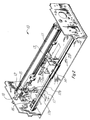
- Figure 1 is a perspective drawing of a portable terminal which incorporates the printer of this invention.
- Figure 2 is a cutaway perspective of the printer of this invention.
- Figures 3a and 3b are cutaway front views illustrating a paper-in and a paper-out condition, respectively.
- Figure 4 is a cutaway front view illustrating a column zero position.
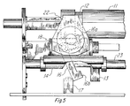
- Figure 5 is a cutaway front view illustrating a paper-out condition about to be changed to a column zero position.
- Figure 6 is a schematic diagram of the generation of the paper-out and column zero signal.
- The printer of this invention has a common mechanism for detecting both paper-out condition and a column zero position in a novel manner. For an understanding of the mechanism, turn first to Figure 1.
- Figure 1 illustrates
portable terminal 1 which incorporates printer 10. In this preferred embodiment, printer 10 is a thermal printer but an ink jet printer also is alternatively employed. The printer could be a wire matrix printer or any other type printer, with a movable carriage for printing on paper. - Figure 2 is a cutaway perspective of printer 10 illustrating platen 11 having
groove 12 formed therein.Carriage 14 is shown riding onguide rod 23 and havingactivation arm 13 attached. Carriage 14 carries printhead 22 (see Fig. 5).Activation arm 13 is positioned and intended to strikeactivation lever arm 16 whencarriage 14 moves to the left.Activation lever arm 16 rotates aboutpivot point 18.Torsion spring 15 bears against the upper end ofdetection lever arm 16 and the lower end oflever arm 16, as shown in the normal state, blocks light from LED 17a from passing to photo transistor 17b, both ofoptical sensor 17. - Figure 3a is a sectional front view illustrating
detection lever arm 16 in its normal state with itslower end 16b positioned withinoptical sensor 17 and with itsupper end 16a urged, byspring 15, againstpaper 21.Paper 21 is shown riding on platen 11, overgroove 12. - Figure 3b illustrates platen 11 with no
paper 21 in place. Under these circumstances,spring 15 has urged theupper end 16a ofdetection lever arm 16 intogroove 12, movinglower end 16b out ofoptical sensor 17, thereby enabling a light path between LED 17a and photo transistor 17b, providing a signal, indicating a paper-out condition. - Figure 4 is a cutaway front view illustrating the column zero position.
Detection lever arm 16 is shown withlower end 16b having been moved away fromoptical sensor 17, pivoted atpoint 18. Note thatdetection lever arm 16 is moved in the opposite direction from the paper-out condition. - Figure 5 is a cutaway front section showing
detection lever arm 16 in the paper-out position but withactivation arm 13 contactingdetection lever arm 16 ascarriage 14 carryingprinthead 22 moves to the left. As the motion ofcarriage 14 continues,activation arm 13 pushesdetection lever arm 16 to the left side ofoptical sensor 17 as indicated in Figure 4. - Figure 6 schematically illustrates LED 17a in association with photo transistor 17b within
optical sensor 17. The collector of photo transistor 17b passes signal PO/COL0 through terminals EB and EA, ultimately to ANDgate 25, forcing the interrupt signal to be sent to a microprocessor which is part of printer 10. At the same time, the PO/COL0 signal is sent throughbuffer 26 to identify the interrupt. - Turn first to Figures 3a and 3b. In Figure 3a,
paper 21 is shown covering platen 11 and also coveringgroove 12, formed in platen 11. - In Figure 3b, it can be seen that
paper 21 is no longer present and therefore theupper end 16a fits intogroove 12, causinglower end 16b to move away fromoptical sensor 17. Then, as can be seen in Figure 6, signal PO/COL0 is sent from photo transistor 17b by way of excitation from LED 17a, to ANDgate 25. ANDgate 25 is ordinarily high, and when signal PO/COL0 is received, its output goes low as an interrupt output. The interrupt is received by the microprocessor in the printer which then takes remedial action, based upon the program that responds to the interrupt. - Figure 4 illustrates
detection lever arm 16 in the column zero position having hadlower end 16b pivoted onpivot 18 to the left ofoptical sensor 17. - Referring again to Figure 6, a PO/COL0 signal is again sent, generating an interrupt to the microprocessor through AND
gate 25. - Column zero is not an ordinary, operational condition. Column zero occurs only upon starting or resetting of the system. Otherwise, during normal operation, column zero cannot occur because the system always return to column one, under control of the microprocessor. Therefore, if signal PO/COL0 occurs during normal operation, it must signify a paper-out condition. The operation of the microprocessor is not part of this invention and will not be described herein.
- Figure 5 illustrates a condition where paper-out has been detected as shown by the position of
detection lever arm 16. In Figure 5,activation arm 13 is shown contactinglever arm 16, and ascarriage 14 proceeds onguide 23 to the left,lever arm 16 will be moved to the left indicating a column zero position. - It may be that there is a paper-out condition simultaneously present with a column zero position. In that case, a microprocessor moves
carriage 14 to the starting position of column one. If signal PO/COL0 is still present, then a paper-out condition exists, and remedial action must be taken. - Those skilled in the art may alter specific configurations shown herein without departing from the scope of this invention which is limited only by the appended claims.
Claims (4)
- A printer (10) for printing characters on paper (21), comprising a platen (11) having a groove (12), a carriage (14) supporting a printhead (22) that traverses the paper (21) which is supported by the platen (11) and covers the groove (12) and a detection mechanism comprising a pivoted lever (16) having an end (16A) which in a normal state is pressed against the part of the paper (21) covering the groove (12), and another part (16B) for selectively blocking light communication between a light emitting means (17A) and a light detecting means (17B), the detection mechanism indicating a paper-out condition by the end (16A) of the lever (16) moving into the groove (12) so as to change the position of the other part of the lever relative to the light communication path,
characterised in that
the end (16A) of the lever is pressed against the paper (21) by a spring (15),
in that
in the normal state the other part (16B) of the lever (16) blocks light communication between the emitting and detecting means (17A,17B) and in the paper-out condition the other part (16B) of the lever (16) does not block light communication between the emitting and receiving means (17A,17B),
and in that
the carriage (14) has associated with it a contacting means positioned to contact and move the lever (16) out of its normal state to allow light communication between the emitting and detecting means (17A,17B) thereby indicating a column zero position of the printhead (22). - A printer according to claim 1 wherein the contacting means comprises an activation arm (13), attached to the carriage (14), positioned to bear against the lever (16) when the carriage (14) moves to the left end position, causing the other part (16B) to move out of the normal state into a state of light communication, indicating a column zero position.
- A printer according to claim 1 or 2 wherein the axis of rotation of the lever (16) is perpendicular to the direction of travel of the carriage (14).
- A printer according to claim 1, 2 or 3 wherein the spring is a coil spring mounted with its axis parallel to the axis of rotation of the lever.
Applications Claiming Priority (2)
| Application Number | Priority Date | Filing Date | Title |
|---|---|---|---|
| US07/251,435 US4881840A (en) | 1988-09-30 | 1988-09-30 | Printer having paper-out and column zero detection mechanism |
| US251435 | 1988-09-30 |
Publications (3)
| Publication Number | Publication Date |
|---|---|
| EP0361753A2 EP0361753A2 (en) | 1990-04-04 |
| EP0361753A3 EP0361753A3 (en) | 1990-10-24 |
| EP0361753B1 true EP0361753B1 (en) | 1994-05-04 |
Family
ID=22951960
Family Applications (1)
| Application Number | Title | Priority Date | Filing Date |
|---|---|---|---|
| EP89309483A Expired - Lifetime EP0361753B1 (en) | 1988-09-30 | 1989-09-19 | Printer having paper-out and column zero detection mechanism |
Country Status (4)
| Country | Link |
|---|---|
| US (1) | US4881840A (en) |
| EP (1) | EP0361753B1 (en) |
| JP (1) | JP2860120B2 (en) |
| DE (1) | DE68915096T2 (en) |
Families Citing this family (15)
| Publication number | Priority date | Publication date | Assignee | Title |
|---|---|---|---|---|
| US5158221A (en) * | 1988-05-24 | 1992-10-27 | Ricoh Company, Ltd. | Automatic document feeder capable of feeding a document in the form of a computer form |
| DE3934398A1 (en) * | 1989-10-11 | 1991-04-25 | Mannesmann Ag | DEVICE FOR RELEASING A ROCKER ARM, BY WHICH A ROCKER ARM CAN BE GENERATED IN ANY SENSOR SIGNAL, IN PARTICULAR FOR SCANING SHEET-SHAPED RECORD CARRIERS IN PAPER PROCESSING DEVICES |
| JP2717138B2 (en) * | 1990-09-12 | 1998-02-18 | セイコープレシジョン株式会社 | Setting method by sensor |
| US5746521A (en) * | 1996-12-20 | 1998-05-05 | Intermec Corporation | Thermal printhead with integrated printhead position sensor |
| JP4686843B2 (en) * | 1999-12-06 | 2011-05-25 | セイコーエプソン株式会社 | Detection device for recording apparatus and recording apparatus provided with the same |
| JP2002273911A (en) * | 2001-03-15 | 2002-09-25 | Seiko Epson Corp | Ink jet printer |
| US7228965B2 (en) * | 2004-09-25 | 2007-06-12 | International Paper Company | Integrated appliance container for support during assembly transport and display |
| JP5440214B2 (en) * | 2010-01-29 | 2014-03-12 | セイコーエプソン株式会社 | Sheet material detection apparatus and recording apparatus |
| JP5520731B2 (en) * | 2010-07-27 | 2014-06-11 | 株式会社沖データ | Medium detection apparatus and image forming apparatus |
| JP2013249186A (en) * | 2012-06-04 | 2013-12-12 | Seiko Epson Corp | Recording apparatus and detection structure in recording apparatus |
| GB2515993B (en) * | 2013-04-08 | 2016-04-27 | Innovative Tech Ltd | A banknote and voucher handling apparatus |
| US9509877B1 (en) | 2015-06-25 | 2016-11-29 | Hewlett-Packard Development Company, L.P. | Indication of whether print job is a cut media or continuous media print job |
| CN111565935B (en) | 2018-01-18 | 2021-12-10 | 惠普发展公司,有限责任合伙企业 | Printer carriage with sensor |
| CN112319065B (en) * | 2018-10-26 | 2022-05-27 | 深圳市汉森软件有限公司 | Method and device for preventing carriage of ink-jet printer from collision and computer readable storage medium |
| CN111550982B (en) * | 2020-04-21 | 2021-12-17 | 宁夏共享机床辅机有限公司 | Material detection device and microwave drying equipment with same |
Family Cites Families (7)
| Publication number | Priority date | Publication date | Assignee | Title |
|---|---|---|---|---|
| US2293283A (en) * | 1940-03-14 | 1942-08-18 | Dow Raymond | Typewriter attachment |
| US2320110A (en) * | 1941-04-29 | 1943-05-25 | George A Walker | Electric indicator for typewriters |
| JPS5625488A (en) * | 1979-08-09 | 1981-03-11 | Canon Inc | Printer |
| JPS5787983A (en) * | 1980-11-21 | 1982-06-01 | Toshiba Corp | Typing machine |
| JPS5845987A (en) * | 1981-09-16 | 1983-03-17 | Seikosha Co Ltd | Deciding method for print starting position of dot printer |
| JPS61102280A (en) * | 1984-10-25 | 1986-05-20 | Oki Electric Ind Co Ltd | Printing medium detecting mechanism for printer |
| US4800402A (en) * | 1988-01-07 | 1989-01-24 | Calcomp Inc. | Plotter paper sizing system |
-
1988
- 1988-09-30 US US07/251,435 patent/US4881840A/en not_active Expired - Lifetime
-
1989
- 1989-09-19 EP EP89309483A patent/EP0361753B1/en not_active Expired - Lifetime
- 1989-09-19 DE DE68915096T patent/DE68915096T2/en not_active Expired - Fee Related
- 1989-09-29 JP JP1255102A patent/JP2860120B2/en not_active Expired - Fee Related
Also Published As
| Publication number | Publication date |
|---|---|
| DE68915096D1 (en) | 1994-06-09 |
| JPH02212182A (en) | 1990-08-23 |
| EP0361753A3 (en) | 1990-10-24 |
| US4881840A (en) | 1989-11-21 |
| DE68915096T2 (en) | 1994-08-18 |
| JP2860120B2 (en) | 1999-02-24 |
| EP0361753A2 (en) | 1990-04-04 |
Similar Documents
| Publication | Publication Date | Title |
|---|---|---|
| EP0361753B1 (en) | Printer having paper-out and column zero detection mechanism | |
| US4793605A (en) | Paper detector of printer | |
| US7549814B1 (en) | Compact low paper sensor mechanism | |
| EP0574332A2 (en) | Thermal printer having a noncontact sensor for determining media type | |
| US6386676B1 (en) | Reflective type media sensing methodology | |
| EP0900754B1 (en) | An optical device for detecting the printing media in printers | |
| US4897670A (en) | Thermal transfer printer | |
| US5139351A (en) | Thermal recording apparatus having a movable platen roller | |
| US6599041B1 (en) | Sheet movement sensor | |
| US5082384A (en) | Paper detecting apparatus for printer | |
| US7777174B2 (en) | Image forming apparatus including a recording medium detector with a light shield | |
| JPH0420394B2 (en) | ||
| US4859099A (en) | Automatic paper loading apparatus for printer having paper bail actuating device | |
| JP2007535738A (en) | Operation elements for cars | |
| US4793723A (en) | Mechanism for detecting end of ink ribbon in a ribbon cassette | |
| JP2694884B2 (en) | Printer | |
| US4639607A (en) | Device for sensing a recording medium in a line printer | |
| JP2002264355A (en) | Level detector and ink jet printer | |
| JP4338301B2 (en) | Printer | |
| US4030589A (en) | Data processing machine | |
| JPH03275A (en) | Printer | |
| US6073928A (en) | Sheet end detecting mechanism | |
| JPH08217326A (en) | Sheet detection device in printer | |
| JPH03197162A (en) | Serial printer | |
| JPH05149721A (en) | Gap sensor for printer |
Legal Events
| Date | Code | Title | Description |
|---|---|---|---|
| PUAI | Public reference made under article 153(3) epc to a published international application that has entered the european phase |
Free format text: ORIGINAL CODE: 0009012 |
|
| AK | Designated contracting states |
Kind code of ref document: A2 Designated state(s): DE FR GB IT |
|
| PUAL | Search report despatched |
Free format text: ORIGINAL CODE: 0009013 |
|
| AK | Designated contracting states |
Kind code of ref document: A3 Designated state(s): DE FR GB IT |
|
| 17P | Request for examination filed |
Effective date: 19910417 |
|
| 17Q | First examination report despatched |
Effective date: 19921116 |
|
| GRAA | (expected) grant |
Free format text: ORIGINAL CODE: 0009210 |
|
| ITF | It: translation for a ep patent filed |
Owner name: BARZANO' E ZANARDO ROMA S.P.A. |
|
| AK | Designated contracting states |
Kind code of ref document: B1 Designated state(s): DE FR GB IT |
|
| REF | Corresponds to: |
Ref document number: 68915096 Country of ref document: DE Date of ref document: 19940609 |
|
| ET | Fr: translation filed | ||
| PLBE | No opposition filed within time limit |
Free format text: ORIGINAL CODE: 0009261 |
|
| STAA | Information on the status of an ep patent application or granted ep patent |
Free format text: STATUS: NO OPPOSITION FILED WITHIN TIME LIMIT |
|
| 26N | No opposition filed | ||
| REG | Reference to a national code |
Ref country code: GB Ref legal event code: IF02 |
|
| PGFP | Annual fee paid to national office [announced via postgrant information from national office to epo] |
Ref country code: GB Payment date: 20060804 Year of fee payment: 18 |
|
| PGFP | Annual fee paid to national office [announced via postgrant information from national office to epo] |
Ref country code: FR Payment date: 20060906 Year of fee payment: 18 |
|
| PGFP | Annual fee paid to national office [announced via postgrant information from national office to epo] |
Ref country code: DE Payment date: 20060929 Year of fee payment: 18 |
|
| PGFP | Annual fee paid to national office [announced via postgrant information from national office to epo] |
Ref country code: IT Payment date: 20060930 Year of fee payment: 18 |
|
| GBPC | Gb: european patent ceased through non-payment of renewal fee |
Effective date: 20070919 |
|
| PG25 | Lapsed in a contracting state [announced via postgrant information from national office to epo] |
Ref country code: DE Free format text: LAPSE BECAUSE OF NON-PAYMENT OF DUE FEES Effective date: 20080401 |
|
| REG | Reference to a national code |
Ref country code: FR Ref legal event code: ST Effective date: 20080531 |
|
| PG25 | Lapsed in a contracting state [announced via postgrant information from national office to epo] |
Ref country code: FR Free format text: LAPSE BECAUSE OF NON-PAYMENT OF DUE FEES Effective date: 20071001 |
|
| PG25 | Lapsed in a contracting state [announced via postgrant information from national office to epo] |
Ref country code: GB Free format text: LAPSE BECAUSE OF NON-PAYMENT OF DUE FEES Effective date: 20070919 |
|
| PG25 | Lapsed in a contracting state [announced via postgrant information from national office to epo] |
Ref country code: IT Free format text: LAPSE BECAUSE OF NON-PAYMENT OF DUE FEES Effective date: 20070919 |