EP0348662A2 - Gestion d'objet et système de délivrance ayant des capacités multiples de résolution d'objet - Google Patents
Gestion d'objet et système de délivrance ayant des capacités multiples de résolution d'objet Download PDFInfo
- Publication number
- EP0348662A2 EP0348662A2 EP89109025A EP89109025A EP0348662A2 EP 0348662 A2 EP0348662 A2 EP 0348662A2 EP 89109025 A EP89109025 A EP 89109025A EP 89109025 A EP89109025 A EP 89109025A EP 0348662 A2 EP0348662 A2 EP 0348662A2
- Authority
- EP
- European Patent Office
- Prior art keywords
- data
- image
- record
- management
- delivery system
- Prior art date
- Legal status (The legal status is an assumption and is not a legal conclusion. Google has not performed a legal analysis and makes no representation as to the accuracy of the status listed.)
- Withdrawn
Links
Images


Classifications
-
- G—PHYSICS
- G06—COMPUTING; CALCULATING OR COUNTING
- G06F—ELECTRIC DIGITAL DATA PROCESSING
- G06F16/00—Information retrieval; Database structures therefor; File system structures therefor
- G06F16/20—Information retrieval; Database structures therefor; File system structures therefor of structured data, e.g. relational data
- G06F16/28—Databases characterised by their database models, e.g. relational or object models
- G06F16/289—Object oriented databases
-
- G—PHYSICS
- G06—COMPUTING; CALCULATING OR COUNTING
- G06F—ELECTRIC DIGITAL DATA PROCESSING
- G06F16/00—Information retrieval; Database structures therefor; File system structures therefor
- G06F16/50—Information retrieval; Database structures therefor; File system structures therefor of still image data
- G06F16/53—Querying
- G06F16/532—Query formulation, e.g. graphical querying
Definitions
- the invention disclosed broadly relates to data processing systems and, more particularly, relates to an object management and delivery system (OMDS) and having multiple object-resolution capability.
- OMDS object management and delivery system
- the disclosed object management and delivery system is particularly suited for use as an image retrieval/storage system.
- Ganske et al (U.S. Patent 4,139,901) is directed to a document storage and retrieval system including a plurality of remotely disposed control terminals and microfiche carousel document storage files with means for converting microfiche images thereon into video signals representative of the document and for transferring these video signals to a buffer storage unit associated with a requesting control terminal.
- Gilbert U.S. Patent 4,164,024 is directed to an information retrieval system which provides a retrievable updatable display of a permanent microfilm record.
- An updated display is accomplished by forming a display of a projected permanent microfilm record onto a gas panel display, and supplanting updated portions by blanking or by overwriting predetermined portions of the display with updated information.
- Johnson et al (U.S. Patent 4,174,890) is directed to a microfilm utilization device wherein a special bar code is printed along the edge of the microfilm, and wherein an automatic call-up feature can be used so that any given photographic area along a length of the microfilm can be selected in response to the push of a button. Thereafter, any image on the microfilm may be selected for projection by a manual movement in second and third dimensions of a simple lens-positioning mechanism.
- Sukonick et al (U.S. Patent 4,197,590) is directed to a computer graphic display system including a random access raster memory for storing data to be displayed. Zoom, pan, split-screen and XOR features can be utilized for the manipulation of a displayed image.
- Ovshinsky et al (U.S. Patent 4,205,387) is directed to a data storage and retrieval system wherein miniaturized heating heads are used to produce a selection of sizes of alpha-numeric, pictorial or digital coded images on a heat-responsive recording medium.
- Kimoto U.S. Patent 4,485,454
- retrieval data are stored to include a number of codes.
- Operator keying requirements for the retrieval of documents are minimized because an operator can input desired codes, and the system will then search for and display a number of selectable retrieval data containing the desired codes.
- Smutek et al (U.S. Patent 4,553,206) is directed to an image storage and retrieval technique in which digitized information is broken up into blocks of a fixed byte size, and each block stored in memory has a header associated therewith, the header identifying the digitized information, detailing how the image was digitized and compressed, and having an address of any other block containing related information for the same image, thereby to create between blocks a chaining by which all blocks related to an image can be quickly located once a first block is located using an index.
- Froessl (U.S. Patent 4,553,261) is directed to a document and data handling system wherein each document is marked with a unique identifier code and then scanned, digitally encoded, and then stored. The system also includes conversion of digitally encoded portions into machine code.
- Kato (U.S. Patent 4,574,395) is directed to a picture image filing apparatus which avoids manual input of retrieval data.
- Retrieval data to be used in retrieving picture image data from an image memory are carried at a predetermined location on an original document itself, and are converted to computer data by the application of a pattern recognition process to digitized data signals from a scanning operation applied to the predetermined location.
- Yoneyama et al (U.S. Patent 4,601,003) is directed to a document storage and rearrangement system which gives a user a visual perception of an actual office storage operation.
- a first picture image pattern provides an operator with a model image representation of a typical office work location, i.e., a desk, filing cabinet, waste basket, etc., and a second picture image pattern presents a visual representation of the document contents of one of the many file folders stored in the system.
- Ciampa et al (U.S. Patent 4,635,136) is directed to a method and apparatus for storing a massive inventory of labeled images (e.g., corresponding to real estate parcels), wherein each labeled image is stored on and produced from a different frame of a video disk.
- labeled images e.g., corresponding to real estate parcels
- Van Tyne (U.S. Patent 4,672,186) is directed to a digital document scanning system including a scanner which permits the presence or absence of a document to be detected and allows dynamic adjustment of threshold levels, thereby accommodating documents which utilize shaded backgrounds.
- Hirose et al (U.S. Patent 4,727,589) is directed to a picture data storage/retrieval system where a plurality of picture data storage/retrieval apparatuses are connected to each other through a communication line, and wherein a given apparatus can request a registration, retrieval or deletion of picture data in a another apparatus.
- Berarducci (WO 87/04826) is directed to a multi-processor apparatus having two data busses and being especially suitable for use in processing digital image signals, wherein data can be transferred from a processor to a memory unit while at the same time data are being transferred from a memory unit to a processor.
- Morton (WO 87/05767) and Morton (WO 87/05768) are directed to a digital image communications network having dual communication channels, i.e., a control channel which handles communication data, and an image channel used for the exclusive transmission of images.
- the prior art has failed to provide an object management and delivery system (OMDS) which will provide fast access time for either magnetic or optical disk storage, will have a minimized communications traffic on the communications networks used by the object management and retrieval system, and yet will maintain the availability of high resolution images for occasional high resolution requirements when the object management and retrieval system is utilized for image storage/retrieval. Further, the prior art has failed to provide an object management and retrieval system which can perform desired object-related operations with only a modicum of interactions between the operations of a host computing system and said object management and retrieval system.
- OMDS object management and delivery system
- a further object of the invention is to provide an improved object management and delivery system which imposes a lower traffic volume on communications systems connected therewith.
- Still a further object of the invention is to provide an improved image storage/retrieval system which has a fast access time for stored images, has a reduced impact on the communications traffic, and yet provides for the availability of high resolution images.
- a further object of the invention is to provide an improved data processing system wherein an object management and delivery system can perform desired object-related operations with only a modicum of interaction between the operations of a host computing system and said object management and delivery system.
- Another object of the invention is to provide an improved data processing system wherein an object management and delivery system can perform object capture, prefetch, display, print and/or modify operations with only a modicum of interaction between the operations of a host computer system and said object management and delivery system.
- an object management and delivery system particularly suited as an image storage/retrieval system having the multiple image resolution capability disclosed herein.
- a data processing system for the storage/retrieval and display of objects and document images, and includes a workstation having a document input scanner coupled thereto for digitizing document images at a first resolution, an image display unit for displaying digitized document images at a second resolution which is less than the first resolution and a printer for printing digitized document images at a third resolution greater than the second resolution, the workstation being coupled to an object storage and delivery manager (OSDM) and storage.
- OSDM object storage and delivery manager
- the system includes in the workstation a higher resolution bit plane memory having an input coupled to the document scanner for receiving a digitized document image at the first resolution.
- the system further includes a higher resolution image compression unit coupled to the higher resolution bit plane memory and having an output coupled to the image host computer, for compressing an object or the first resolution digitized document image and outputting a first compressed image record to the object storage and delivery manager for storage.
- a higher resolution image compression unit coupled to the higher resolution bit plane memory and having an output coupled to the image host computer, for compressing an object or the first resolution digitized document image and outputting a first compressed image record to the object storage and delivery manager for storage.
- the system further includes a first object storage unit coupled to the object storage and delivery manager for storing compressed records of objects and images digitized at the first resolution, the object storage and delivery manager storing the first compressed image record in the first object storage unit.
- the system further includes a resolution modification unit having an input, coupled to the higher resolution bit plane memory, for reducing the resolution of the first resolution digitized object or document image to the second resolution and for outputting a second resolution digitized object or document image.
- a resolution modification unit having an input, coupled to the higher resolution bit plane memory, for reducing the resolution of the first resolution digitized object or document image to the second resolution and for outputting a second resolution digitized object or document image.
- the system further includes in the workstation a lower resolution bit plane memory having an input coupled to the resolution modification unit for receiving the second resolution digitized object or document image.
- the image display unit has an input coupled to the lower resolution bit plane memory for receiving the second resolution digitized image or document image for display.
- the system additionally includes a lower resolution image compression unit coupled to the lower resolution bit plane memory and having an output coupled to the image host computer, for compressing the second resolution digitized object or document image and outputting a second compressed image object or record to the object storage and delivery manager for storage, the second compressed image object or record being smaller in size than the first compressed object or image record.
- a lower resolution image compression unit coupled to the lower resolution bit plane memory and having an output coupled to the image host computer, for compressing the second resolution digitized object or document image and outputting a second compressed image object or record to the object storage and delivery manager for storage, the second compressed image object or record being smaller in size than the first compressed object or image record.
- the system further includes a second object storage unit coupled to the object storage and delivery manager for storing compressed records of objects or images digitized at the second resolution, the object storage and delivery manager storing the second compressed object or image record in the second object storage unit.
- the system further includes a higher resolution object decompression unit, having an input coupled to the object storage and delivery manager, for receiving and decompressing the first compressed object or image record from the first object storage unit to restore the first resolution digitized object or document image.
- a higher resolution object decompression unit having an input coupled to the object storage and delivery manager, for receiving and decompressing the first compressed object or image record from the first object storage unit to restore the first resolution digitized object or document image.
- the system further includes an object or image scaling unit, having an input coupled to the higher resolution object decompression unit, for converting the first resolution digitized object or document image into a third resolution digitized object or document image having the third resolution.
- an object or image scaling unit having an input coupled to the higher resolution object decompression unit, for converting the first resolution digitized object or document image into a third resolution digitized object or document image having the third resolution.
- the system further includes a printer having an input coupled to the image scaling unit, for receiving the third resolution digitized object or document image for printing.
- a lower resolution object decompression unit having an input coupled to the object storage and deliver manager, for receiving and decompressing the second compressed object or image record from the second object storage unit to restore the second resolution digitized object or document image.
- the lower resolution bit plane memory has an input coupled to the lower resolution object decompression unit for receiving the second resolution digitized object or document image for display on the image display unit.
- the resulting system reduces communications traffic on the network because of the smaller compressed data records which are transmitted for the low resolution operations. Access time for storing and reading the lower resolution compressed data records is also reduced; however, this lower traffic and faster access time are obtained without sacrificing the availability of high resolution compressed data records which are occasionally needed for printing and other high resolution operations.
- the resulting method allows an object delivery and management system to perform object capture, prefetch, display, print and/or modify operations with only a modicum of interactions between the operations of a host computer system and the object management and delivery system.
- the invention relates to an object management and delivery system having multiple object-resolution capability.
- An "object” is defined as any stream of data bits.
- Digitized data which are derived from signals resulting from, and related to, objects and which may be utilized in reproduction of the objects, are referred to as "object data".
- This object data may be stored or transmitted using magnetic, electronic or optical techniques and, further, transmission may be conducted in the digital or analog form.
- Object data related to a single or multi-page document will be referred to as a "record”.
- object was purposely given a comprehensive definition so as not to limit the scope of the invention.
- inventive object management and delivery system is particularly suited for use as an image storage/retrieval system wherein object data are more specifically "image data" which are derived from signals resulting from, and related to, electronic scanning of documents, and which may be utilized in reproduction of images representative of the documents.
- image data are more specifically "image data” which are derived from signals resulting from, and related to, electronic scanning of documents, and which may be utilized in reproduction of images representative of the documents.
- the documents may be of current interest and/or purely of historic interest and the documents may contain information printed or typewritten by machine, printed or written by hand, or pictures, drawings and other forms of representations commonly referred to as "graphics". It is very often necessary to access selected documents for various purposes within a short time from a large volume of documents. Not all of the information contained in the documents may be of importance. In addition, documents may be of greater or lesser degrees of importance, depending upon the type and contents of the documents as well as the nature of the organization.
- each office has a need for being able to obtain a listing of documentation maintained in a given file associated with a particular customer and to readily examine a copy of any one of the particular documents so listed. In this way, each insurance claims officer can be fully informed of the background situation involved with any transaction or any given claim being handled through his or any other office of the company.
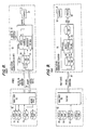
- FIGS. 1 and 2 are architectural diagrams including the dual density digital image system of the present invention.
- OMDS object management and delivery system 12
- HCS host computing system 13
- the installation operating system may represent an operating system in existence before installation of the image system
- the host operating system 13 may include, for example, a file management system 19 (hereinafter "FMS") which is connected to data terminals 18 and which maintains an electronic data base (not shown) having work files containing data pertinent to a particular subject (e.g., an insurance customer file). Due to storage and access time limitations associated with such a system, the data base of the file management system 19 typically contained an index with abbreviated comments as to objects, e.g. hardcopy documents associated with that subject. Without the object management and retrieval system of the present invention, a user would have to manually retrieve or request a stored hardcopy in order to view a representation of a desired document.
- FMS file management system 19
- Each of the data terminals 18 is part of a workstation 20 which further includes at least an image terminal 21. While in the presently preferred embodiment the data terminal 18 and image terminal 21 for each workstation are provided as discrete devices to segregate the operation of the operating system 13 (i.e., to allow the operating system to operate in the event of an image system failure), an embodiment is also envisioned where the data terminal and image terminal devices for each workstation 20 are incorporated into a single device.
- Each of the image terminals 21 is connected to a communication network 38 (e.g., a token ring network including a network controller) which is connected to an object storage and delivery manager 48 (hereinafter OSDM).
- OSDM object storage and delivery manager 48
- the OSDM 48 is able to communicate with the file management system 19 regarding document registration, document retrieval and routing requests (all to be described below), and in response thereto is able to retrieve object data stored in an object storage and to provide this object data to one or more of the image terminals 21 through the communication network 38.
- the OSDM comprises an object storage manager (OSM).
- the object storage comprises, for example, a magnetic disk DASD (Data Acquisition and Storage Device) 50, 60, magnetic DASD controller 49, optical library 52, back-up optical drive 53 and optical controller 51 all connected via network 39.
- the hardware and software of the OMDS 12 und operating system 13 at a given installation may be close together (e.g., in the same room) or widely disbursed (e.g., on different floors) as long as the important communication link 17 between the two is maintained.
- the organizational installation 10, including the OMDS 12 and operating system 13 may be in a first city (e.g., Washington, D.C.)
- installation 10a (FIG. 1) is an example of a installation which can be located quite a distance away from the first installation, e.g., in Los Angeles.
- the invention is not limited and may be applied in multiple concurrent installations, with each installation being able to retrieve object data from any other installation. For sake of simplicity and ease of discussion, only two installations are shown.
- file management system 19 can request object data from OSDM 48a via communications link 16.
- file management processor 19a can request object data from OSDM 48.
- object data are not transferred back to the requesting file management system, but instead must be routed to the requesting installation's local image terminal (e.g., 21) through the OSDM (e.g., 48) which is associated with the requesting installation.
- the file management systems can request object data from a distant image system through the communication links 16 or 16a, the object data must be routed to the OSDM of the requesting installation through the communication link 15.
- an OSDM may require retrieval of object data which it does not own (i.e., data which are not stored in it's associated object store, but are instead stored in the object store of a different image host processor (e.g., 48a)).
- the OSDM is able to use a communication link 15 to request and retrieve needed object data.
- the communication exchange is between two OSDMs, such a communication can be coined a "mirror" operation.
- FIG. 2. depicts a single workstation 20 (excluding a data terminal) and its connection over a network line 38 to the object host and storage 40. Although there is only a single workstation 20 depicted, it should be apparent from FIG. 1 that there may be many workstations 20 connected in a local area network to a single object host and storage 40 or to a plurality of object hosts and storages 40.
- Document input scanner 22 is coupled through an adapter 22′ (FIG. 3) to the system bus 37 of the workstation.
- the document input scanner 22 digitizes document images at a first resolution which, in this example, is a 200 pel per inch resolution.
- a first resolution which, in this example, is a 200 pel per inch resolution.
- FIGS. 4 and 5 an example is given in FIGS. 4 and 5 of how the line A - B is depicted in a high resolution digitization of FIG. 4 and a lower resolution digitization of FIG. 5.
- the line A - B is digitized into pel elements in a 16 x 16 matrix resulting in a total of 256 bits for a bit plane representation of the image area.
- the resolution is cut in half so that the image area is divided into an 8 x 8 matrix, and 64 bits are required for the bit plane representing the image area.
- Image display unit 30 is coupled to the workstation for displaying a digitized object or document image at the second lower resolution which in this example is 100 pels and is illustrated by the lower resolution image in FIG. 5.
- printer 46 is coupled to the workstation for printing digitized objects and document images at a third resolution of 300 pels per inch. This resolution is greater than the input resolution from the document scanner 22, which is 200 pels per inch. As will be appreciated by one skilled in the art, the 300 pel per inch printing resolution has been adopted to advantageously render the preferred embodiment consistent with current printing standards. The processing and adaptation of originally scanned 200 pel per inch object or image data into 300 pel per inch data for printing are well known in the art and are not the subject of the invention.
- the workstation image terminal is coupled over a communication adapter 36 (FIG. 2 or 3) and the network line 38 to the object host and storage 40.
- the communication adapter 36 may be, for example, an IBM token ring adapter.
- a higher resolution bit plane memory 24 has its input coupled to the document scanner 22 for receiving a digitized document image at the first, higher resolution of 200 pels, such as that represented in FIG. 4.
- the system memory 41 for the workstation 20 can be envisioned as being partitioned into several instruction code regions and several storage or buffer regions. One of the storage regions in memory 41 is set aside for the high resolution bit plane 24. In practice these several instruction code regions and buffer regions may be provided in a single memory means or several memory means.
- a higher resolution object compression unit 32 having an input coupled to the higher resolution bit plane memory 24 and an output coupled through the compressed higher resolution data buffer 34, and thus this output is available to the communication adapter 36 and the line 38 connected to the object host processor 48 in the object host and storage 40.
- the compression unit 32 compresses the first or higher resolution digitized object or document image such as that depicted in FIG. 4, and outputs a first compressed object record to the object host computer 48 for storage.
- Object or image compression can be performed in a variety of ways which are well known in the art.
- a simple approach applying run length encoding principles can be explained to compress an exemplary digitized bit plane image.
- the line A - B has been digitized in the bit plane 24 into an array of black and white pels, where each white pel is represented by a zero binary value, and each black pel is represented by a one binary value, for a total of 256 bits in the bit plane 24.
- a simple run length encoding technique always starts with a white pel in a row, and then the number of consecutive white pels along the row is counted. For a 16 x 16 matrix, there will not be more than sixteen consecutive pels having the same black or white value; therefore, a four-bit representation for each run can be used.
- a next four-bit expression is used to count the number of consecutive next pels of the same color.
- the first two pels starting at the left side are white; therefore, a first four-bit value of 0010 can be used to run length encode the first two pels.
- the third pel in the first row is a black pel, and there is only a single black pel. Therefore, the next four-bit expression for the row is 0001, the number of black pels equaling one.
- the technique for this exemplary run length encoding stops generating four-bit run length coding numbers so that the last consecutive run of like colored pels is not numbered at all, and the difference from the value of sixteen gives the remaining run length and coded value for the final number of pels. In this case, its thirteen white pels complete the first row in FIG. 4.
- compressed higher resolution data such as that shown in FIG. 4 are generated by the object compression unit 32 and stored in the buffer 34.
- a first object storage unit 50 is a magnetic disk DASD (Data Acquisition and Storage Device) which is coupled to the image object host processor 48 for storing compressed records of objects or images digitized at the first, high resolution such as that shown in FIG. 4.
- the object host processor 48 controls the storing of the first, higher resolution compressed image records in the compressed higher resolution data storage 50.
- a resolution modification unit 26 has an input coupled to the higher resolution bit plane memory 24, for reducing the resolution of the first digitized object or document image corresponding, for example to that shown in FIG. 4 to a second, lower resolution object or image, such as that shown, for example in FIG. 5. This lower resolution is then outputted as a second resolution digitized document object to the lower resolution bit plane memory 28.
- resolution modification unit 26 can be embodied in the memory 41 as a resolution modification code 26′ which can be executed by the CPU 35 in the workstation.
- the resolution modification unit operates to make the transition from a high resolution bit plane representation such as that shown in FIG. 4, to the bit plane representation shown in FIG. 5, by converting from a higher resolution matrix (e.g., a 16 x 16 matrix) down to a lower resolution matrix (e.g., an 8 x 8 matrix).
- the workstation 20 further includes a lower resolution bit plane memory 28, which has an input coupled to the resolution modification unit 26, for receiving the second, lower resolution digitized object or document image.
- the lower resolution bit plane 28 can also be embodied as a partitioned portion of the memory 41.
- the image display unit 30 has an input, coupled to the lower resolution bit plane memory 28, for receiving the second, lower resolution digitized object or document image for display.
- Lower resolution object compression unit 56 has an input coupled to the lower resolution bit plane memory 28, and an output coupled through the compressed lower resolution data buffer 58 to the communication adapter 36 and thus the network line 38 connected to the object host processor 48 of the object host and storage 40.
- the object compression unit 56 compresses the second, lower resolution digitized object document or image, and outputs a second object record to the object host computer 48 for storage.
- the second, lower compressed object record is smaller in size than the first, higher compressed object record, as can be seen, for example, in a comparison of FIGS. 4 and 5, where the compressed higher resolution data from the run length encoding operation occupies 128 bits, and the run length encoded version of the compressed lower resolution data occupies 48 bits.
- the object host and storage 40 also includes a second storage unit 60 in the form of a magnetic disk DASD (Data Acquisition and Storage Device) which is coupled to the object host processor 48 for storing compressed records of objects or images digitized at the second, lower resolution corresponding, for example, to FIG. 5.
- the object host processor 48 controls the storage of the second, lower resolution compressed object records in the second image storage unit 60.
- Higher resolution decompression unit 42 has an input coupled from the network line 38 through the communication adapter 36 and the compressed higher resolution data buffer 34, for receiving and decompressing the first higher resolution ccmpressed objects, and for decompressing the first object records from the first object storage device 50, to restore the first, higher resolution digitized object or document image.
- the higher resolution data decompression unit can be embodied as a part of the image compression/decompression processor 39 which is connected over the system bus to the CPU 35 in the workstation 20.
- the compression units 32 and 56 and the decompression units 42 and 62 in the workstation 20 can all be embodied in the same image compression/decompression processor 39.
- An example of such a processor is described in the U. S. Patent 4,610,027, by Anderson, et al., "Method for Converting a Bit Map of an Image to a Run Length or Run End Representation," assigned to the International Business Machines Corporation, and incorporated herein by reference.
- An object scaling unit 44 has an input coupled to the higher resolution object decompression unit 42, and converts the first, higher resolution digitized object into a third resolution digitized document object having a third resolution which, in this example, is 300 pels per inch.
- This third resolution is adapted for the printer 46 which has an input coupled through the printer adapter 46′ to the object scaling unit 44.
- the printer is capable of printing a high resolution image, and the scaling unit 44 will convert the higher resolution 200 pel image, which has been accessed from the object host and storage 40, into the appropriate resolution for driving the printer 46.
- Reference to FIG. 2 will show that the object scaling unit 44 can be embodied in an executable code which is the object scaling code 44′ stored in the memory 41 and executed by the CPU 35.
- the resulting system reduces communications traffic on the network because smaller compressed data records are available for transmission for low resolution operations. Access time for storing and reading lower resolution compressed data records is also reduced; however, because of the image system's concurrent ability also to maintain high resolution object data in the high resolution magnetic disk DASD 50 or the permanent optical storage 52 (discussed ahead), this lower traffic and faster access time are obtained without sacrificing the availability of high resolution compressed data records which are occasionally needed for the high resolution printer and other high resolution operations.
- Magnetic disk DASD storage 50 and 60 represents a preferable storage facility where a lower resolution record is being maintained, or, where a record is "active" in the sense that the record has recently been entered into the OMDS and/or the record is one which will likely be requested or modified soon.
- magnetic disk DASD storage is typically limited in terms of storage space.
- a third object storage unit 52 can be included which, for example, can be a high capacity optical storage device suitable for the permanent storage of digitized objects.
- the third image storage device 52 is coupled to the object host processor 48 and stores compressed records of object digitized at the first, higher resolution.
- the presently preferred embodiment contemplates a transfer of these records to storage in the permanent third object storage device 52.
- the storage operation for a transfer from active to permanent storage is illustrated by the flow diagram of FIG. 6.
- the host processor 48 will transfer the first, higher resolution compressed records from the first storage DASD 50 to the third optical storage device 52 after a predetermined aging period, for example, 30 days.
- This aging period enables systems' operators to have current digital object records on hand on the DASD storage device 50 over a predetermined interval of time, such as 30 days, during which operations with the stored objects will usually be completed.
- the object host computer 48 in response to requests from the command input unit 25 at a workstation 20, will selectively access a first, high resolution compressed object record from the first storage DASD 50.
- the object host processor 48 will selectively access the first high resolution compressed image record from the third storage, or the optical storage device 52.
- the host processor 48 will be able to determine an elapsed period associated with an object by deriving this information from chronological digits of a permanent object name (discussed ahead) associated with the record.
- the host processor 48 will discard the second, lower resolution compressed object records, such as the exemplary record shown in FIG. 5, from the second storage DASD 60 after the expiration of the predetermined period (e.g., 30 days). Thereafter, if a request is made at the command input unit 25 to retrieve a copy of a digitized object for display on the display device 30, the following operations would be followed.
- the predetermined period e.g. 30 days
- the host processor 48 will access higher resolution (e.g., the 200 pel per inch) object data record of the digitized object from the permanent optical storage 52.
- the compressed high resolution record will be decompressed in the high resolution data decompression unit 42 of the workstation 20.
- the resulting digitized high resolution object will be directed over line 54 to the higher resolution bit plane memory 24 where it will be applied to the resolution modification unit 26, thereby resulting in a lower resolution object which is applied to the lower resolution bit plane memory 28 for application to the image display 30.
- This operation is depicted in the flow diagram of FIG. 7 for the display operation.
- the dual density capability of the image retrieval/storage system is further explained in co-pending application "Dual Density Digital Image System".
- the invention has produced a method which allows an object management and delivery (OMDS) system to perform desired object-related requests with only a modicum of interaction between the operations of a host computing system (e.g., the previously discussed file management system) and the OMDS.
- OMDS object management and delivery
- modicum of interaction is defined as a small or moderate amount of interaction.
- a non-exhaustive list of typical interactions include: object-related requests transferred from the FMS to the OMDS; object registration data transferred from the OMDS to notify the FMS that an object record has been stored; and/or error data transferred from the OMDS to notify the FMS when the OMDS encounters and error in trying to perform an object operation request by the FMS.
- a single or multi-page document 1 arrives at the organizational installation, e.g., at a mailroom.
- a request is sent from a workstation (hereinafter "WS") data terminal to the file management system (hereinafter "FMS") via processing path P2 for a temporary document ID.
- a temporary document ID can be any type of ID number (e.g., "ABC” or any other randomly generated number), as long as a different temporary document ID is assigned upon each request to distinguish different respective documents.
- a temporary document ID is assigned by the FMS and returned via processing path P3 and is posted (e.g., via manual handwriting or machine printing) on the document 1.
- the temporary document ID may be posted on a non-important area (e.g., on a back-side), of the document, on simply the first page or, for extra safety, on each page of the document.
- a step S4 the FMS generates and sends to the OMDS associated with the requesting WS data terminal, a permanent document name coordinated with the name with the temporary document I.D. currently associated with the document.
- the receipt and storage of the permanent document name in the OMDS act as an authorization to allow input scanning of a document having associated temporary document ID.
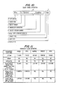
- FIG. 10 A presently preferred object-naming convention is illustrated in FIG. 10.
- a first name portion 6 generated by the FMS comprises: application digits "UF” specifying an application (e.g., insurance division, parking ticket division, etc.) to which the object is relevant; state code “ss” specifying a geographical or other location data; object number “Ccc.Uccccccc” including a uniqueness number "U”; object version number “V” which would typically be some default value (e.g., " ⁇ ” unless a later version of an object is created later in same day) and chronologic digits "mmddyy” specifying the date the object was received.
- application digits "UF” specifying an application (e.g., insurance division, parking ticket division, etc.) to which the object is relevant
- state code “ss” specifying a geographical or other location data
- object number “Ccc.Uccccccccc” including a uniqueness number "U”
- object version number "V” which would typically be some default value (e.g., " ⁇ ” unless
- step S5 the document 1 is manually transported as indicated by processing path P5 to a WS document scanner station. It should be noted that this transport operation may occur over a substantial period of time (e.g., hours, days, weeks) and typically will result in the document being transported to a WS document scanner station which is remote from the WS data terminal used to originally request the temporary document ID.
- a WS document scanner station which is remote from the WS data terminal used to originally request the temporary document ID.
- step S6 the temporary document ID transposed on the document is entered into the image terminal 21 and is sent as indicated by processing path P6 to the OSDM to verify correctness and storage authorization.
- step S7 the OSDM returns an indication represented by processing path P7 of whether or not the temporary document ID entered is invalid or valid. If invalid, the OSDM reports an error and processing jumps to step S6 to allow a user to reenter the temporary document ID. (Alternatively, processing could jump to END.) If valid, the OSDM returns a verification indicating that scanning is authorized for that document.
- step S8 the document is scanned via scanner 22, the image data quality is verified by an operator viewing an image monitor or printout of the document, and the image data is sent to the OSDM.
- step S9 the OSDM stores the object data as a record using the permanent document name.
- the record is "active" in the sense that it was recently input into the system and there is a likelihood that the record may be requested or modified, in a preferred embodiment the record would be stored in magnetic DASD 50 or 60 to accommodate prompt retrieval and/or modification.
- first name portion 6 (discussed above) is generated by the FMS
- second name portion 7 (FIG. 10) is generated by the OSDM.
- First digital "t” indicates object type, for example, one version of the digit "t” might indicate that the object is of legal significance (e.g., customer correspondence).
- Second digit "x” indicates copy type, e.g., that scanning was conducted from an original document or a photocopy.
- digits "pp" indicate the resolution (e.g., 100 pels per inch or 200 pels per inch) of the object data contained in the record.
- step S10 steps S6 to S10 are repeated if a capture is also to be conducted at a different resolution.
- storage for a document in a capture operation is conducted to store both a low resolution (e.g., a 100 pel per inch) record and a high resolution (e.g., a 200 pel per inch) record.
- a low resolution e.g., a 100 pel per inch
- a high resolution e.g., a 200 pel per inch
- the low resolution record is stored because an object will typically be an active object for a short period of time thereafter (e.g., 30 days), and the low resolution record will represent an alternative where data retrieval and network traffic are minimized. Note that retrieval and transmission of a low resolution record is especially preferred where an object image is to be displayed on the preferred 100 pel per inch image monitor.
- the high resolution record is stored to provide sufficient object data which can be used to perform a high-quantity printing reproduction of the original document, and also, for the expected permanent storage of the object record as a high resolution record.
- inventive OMDS can be constructed to allow an operator to override this default situation.
- step S11 the OMDS notifies the FMS that an object data record associated with that permanent object name has been stored.
- the FMS can be constructed to thus update a listing of documentation of a subject workfile associated with said object. Operators at workstations 20 would thus be able to access an image reproduction of the object, whether by display on an image monitor or by printing.
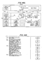
- FIG. 6 is a data flow diagram showing further details of the capture or store operation.
- the image system 12 comprises an object storage which includes low resolution DASD 60, high resolution DASD 50 and optical storage 52.
- the IHP could store records at random or at the next sequential storage location and then search the index of each magnetic disk and optical disk to retrieve an object.
- the preferred embodiment of the invention makes use of the permanent object name and storage management rules (discussed below) to determine the appropriate (for storage) or likely (for retrieval) place of record storage.
- the OMDS can interrogate the state code digits "SS" of the object name (FIG. 10) to determine whether object storage is in the current (i.e., local) object storage or at a remote object storage).
- records are typically maintained in magnetic disk DASD 50 or 60 for a period of at least 30 days.
- the OMDS can make an assumption and make an initial attempt to retrieve the desired object from magnetic disk DASD. Upon failure of this attempt, the OMDS could then attempt retrieval from optical storage.
- the "txpp" digits of the record's object name can further be used to increase the operating speed efficiency of storage and retrieval operation.
- a record may be stored in different storage apparatus during different periods of the record's life. Further, it may be desired to apply different storage rules and life span rules to different types of records.
- a "prefetch" operation is useful in situations where it is known that a particular record will be requested within a short period of time.
- an insurance business environment may have a set-up where correspondence inquires are followed up with a bank of telephone operators making telephone solicitations to potential customers.
- correspondence inquiries could be scanned and converted into records when received, and the FMS could then maintain a work queue of outstanding inquiries and periodically make a request for a "prefetch" of records pertaining to telephone solicitations which are to be conducted shortly.
- step S20 the FMS selects an object record from the work queue or a request is made from a WS data terminal.
- a prefetch command is built and transferred to the OMDS likely to own the object data or record for the desired document. (Note that the state code digits "SS" of the document name (FIG. 10) may prove useful in a determihation of whether a local or remote storage is suspected.) If the OMDS 12 is determined likely to own the record, the prefetch command is transferred via processing path P21a. In contrast, if a remote OMDS 12a is determined likely to own the record, the prefetch command is transferred via dashed (---) processing path P21b.
- step S22 a retrieval command is built and sent to the appropriate storage facility by the OSDM a copy of the desired object data record is retrieved, and the copy is transferred to the OSDM associated with the requesting FMS or WS data terminal. Note that if a remote OMDS owns the image data record for the desired object, operations utilizing dashed (---) processing paths P22a and P22b would be required. If the prefetch command was initially transferred to the remote OMDS, operations utilizing only dashed (---) processing paths P21b and P22b would be required.
- step S23 the OSDM associated with the requesting FMS or WS data terminal stores a copy of the object data record for the expected future access.
- the object data record will be stored in the OSDM if it contains sufficient storage facilities. Otherwise, the object data record will be stored in the magnetic disk DASD 50 or 60.
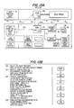
- step S30 an object display request is made by an operator at a WS data terminal as indicated by processing path P30.
- the FMS receives the request and (as indicated by the processing operation P31) builds a display command.
- part of the display command will contain an object name portion 6 such as that illustrated in FIG. 10
- step S32 the FMS display command is asynchronously transferred as indicated by processing path P32 to the OSDM associated with the requesting WS data terminal.
- no response will be returned from the OSDM to the FMS, i.e., communication from the OSDM to the FMS occurs only when the OSDM encounters an error in trying to perform the display operation requested by the FMS.
- step S33 a retrieval command is built by the OSDM, the desired object data record is retrieved from the appropriate storage apparatus, and the object data record is transferred to the OSDM associated with the requesting WS data terminal. It should be noted that if a remote OMDFS owns the object data record for the desired document, dashed (---) processing paths P33a and P33b would be required.
- step S34 the object data record is transferred as indicated by processing path P34 from the OSDM to the WS image terminal for display.
- FIG. 7 is a data flow diagram showing further details of the display operation.
- print operations requests are available in the preferred embodiment, i.e., a print operation may be requested by a WS data terminal, a WS image terminal not having a printer apparatus, and a WS image terminal having a printer apparatus.
- the print operations for each type of request will be separately discussed below.
- step S40 an object print request is made by an operator at a WS data terminal as indicated by processing path P40.
- the FMS receives the request and (as indicated by the processing operation P41) builds a print command.
- part of the print command will contain an object name portion 6 such as that indicated in FIG. 10.
- step S42 the FMS print command is asynchronously transferred as indicated by processing path P42 to the OSDM associated with the requesting WS data terminal.
- no response will be returned from the OSDM to the FMS, i.e., communication from the OSDM to the FMS occurs only when the OSDM encounters an error in trying to perform the display operation requested by the FMS.
- step S43 a retrieval command is built by the OSDM, the desired object data record is retrieved from the appropriate storage apparatus, and the object data record is transferred to the IHP associated with the subject printer which is to reproduce the desired object from the object data record. It should be noted that if a remote OMDS owns the object data record for the desired object, dashed (---) processing paths P43a and P43b would be requ-reo.
- step S44 a print command is transferred as indicated by processing path P44, with object data through the printer work station (PWS) image terminal to the printer for printing.
- PWS printer work station
- FIG. 15A was purposefully constructed to illustrate that the subject printer might be at a WS which is distant from the requesting WS.
- a "print displayed page” operation is used in situations where an operator, viewing an object image at an image monitor PWS, desires to print the displayed page. Reference is made to FIGS. 16A and 16B.
- step S50 a print request is made by an operator at a PWS image terminal whereupon, in a step S51, the PWS image terminal builds a print command.
- the print command and object data are transferred to the PWS printer. Processing then continues with step S55.
- step S52b the print command is transferred via processing path P52b to the OSDM associated with the subject printer.
- part of the print command will contain an object name portion 6 such as that indicated in FIG. 10.
- step S53 a retrieval command is built by the IHP, the desired object data record is retrieved from the appropriate storage apparatus, and the object data record is transferred to the OSDM associated with the subject printer which is to reproduce the desired object from the object data record. It should be noted that, if a remote OMDS owns the object data record for the desired object, dashed (---) processing paths P53a and P53b would be required.
- step S54 a print command is transferred as indicated by processing path P54, with object data through the PWS image terminal to the printer for printing.
- step S55 any printing errors are reported to the PWS image terminal originating the print request.
- a "print displayed page to printer workstation" operation is used in situations where an operator, viewing an object image at a WS, desires to print the displayed page to a PWS which services the print requests of that WS. Reference is made to FIGS. 17A and 17B.
- step S60 a print request is made by an operator at a WS image terminal whereupon, in a step S61, the WS image terminal builds a print command.
- step S62 the print command is transferred as indicated by processing path P62 to the OSDM associated with the subject PWS printer.
- the WS image terminal contains an object data record at a resolution sufficient for printing (i.e., a 200 pel per inch record which can be expanded to a 300 pel per inch record)
- the object data record is transferred to the OSDM. Processing then jumps to a step S64.
- step 63b a retrieval command is built by the OSDM, the desired object data record is retrieved from the appropriate storage apparatus, and the object data record is transferred to the OSDM associated with the subject PWS printer. It should be noted that, if a remote OMDS owns the object data record for the desired object, dashed (---) processing paths P63b and P63c would be required.
- step S64 a print command is transferred, as indicated by processing path P64, with object data through the PWS image terminal to the printer for printing.
- step S65 any printing errors are reported to the WS image terminal originating the print request.
- FIG. 9 is a data flow diagram showing further details of a print operation.
- modify operations are available in the preferred embodiment, i.e., a modify operation may be requested to be performed without additional scanning, or to be performed with additional scanning.
- the operations for each type of modify request will be separately discusscd below.
- a "modify without scanning" operation is used in situations where, for example, a object must be modified by a deletion of excessive or extraneous pages or materials. Reference is made to FIGS. 18A and 18B.
- step S70 a modify request is made as indicated by processing path P70 by an operator at a WS image terminal, whereupon, in a step S71, the FMS builds a modify command.
- part of the modify command will contain an object name portion 6 such as indicated in FIG. 10.
- step S72 the FMS modify command is asynchronously transferred, as indicated by processing path P72, to the OSDM associated with the requesting WS data terminal.
- the OSDM associated with the requesting WS data terminal.
- no response will be returned from the OSDM to the FMS, i.e., communication from the OSDM to the FMS occurs only when the OSDM encounters an error in trying to perform the modify operation or when the OSDM sends an acknowledgement that a modified object data record has been stored.
- step S73 a retrieval command is built by the IHP, the desired object data record is retrieved from the appropriate storage apparatus, and the object data record is transferred to the OSDM associated with the requesting WS data terminal. It should be noted that, if a remote OMDS owns the object data record for the desired object, dashed (---) processing paths P73a and P73b would be required.
- step S74 the object data record is transferred, as indicated by processing path P74, from the OSDM to the WS image terminal for modification.
- step S75 the desired modification is performed (e.g., the deletion of extraneous pages) at the WS image terminal and is transferred back to the IHP with a store command, whereupon, in a step S76, the modified object data record is stored. If the object record has been subsequently modified during the same day it was initially entered into the system, or is modified several times in the same day, this will be reflected in the version digit "V" of the object name (See FIG. 10).
- step S77 the OSDM sends acknowledgement of the stored object data record to the WS image terminal.
- steps S74 to S78 are repeated if an object modify operation is to also be conducted at a different resolution, e.g., an operation may have modified a 100 pel per inch record and wish to modify the corresponding 200 pel per inch record.
- the OSDM notifies the FMS that a modified object data record has been stored. Operators at workstations would then be able to access a reproduction of the modified object, whether it be by display or an image monitor or by printing.
- a "modify with scanning" operation is used in situations where, for example, a object must be modified by an addition of new pages or materials. Reference is made to FIGS. 19A and 19B.
- a mcdify request is made as indicated by processing page P81 by an operator at a WS image terminal to signal that new object pages are to be added to an object data record, whereupon, in a step S82 a temporary object ID is returned by the FMS and is posted on the object pages either by manual handwriting or machine printing.
- the modify command is built by the FMS and the FMS modify command is asynchronously transferred as indicated by processing path P72 to the OSDM associated with the requesting WS data terminal.
- part of the modify command will contain an object name portion 6 such as that indicted in FIG. 10.
- the temporary object ID will also be transferred and associated with the modify command.
- the storage of the above in the OSDM acts to flag a modification authorization.
- step S84 the new object pages Z are manually transported, as indicated by the processing path P84 to the WS document scanner station. It should be noted that this transport operation may occur over a substantial period of time (e.g., hours, days, weeks) and typically will result in the object being transported to a WS document scanner which is remote from the WS data terminal used to originally request the temporary object ID.
- this transport operation may occur over a substantial period of time (e.g., hours, days, weeks) and typically will result in the object being transported to a WS document scanner which is remote from the WS data terminal used to originally request the temporary object ID.
- step S85 the temporary object ID transposed on the new pages is entered into the image terminal and is sent, as indicated by processing path P85, to the OSDM to verify correctness and storage authorization.
- step S86 the OSDM returns an indication represented by processing path P86 of whether or not the temporary object ID entered is invalid or valid. If invalid, the OSDM reports an error and processing jumps to step S85 to allow a user to reenter the temporary object ID. (Alternatively, processing could jump to END.) If valid, the OSDM returns a verification indicating that scanning is authorized for that object.
- step S87 a retrieval command is built by the OSDM, the desired object data record is retrieved from the appropriate storage apparatus, and the object data record is transferred to the OSDM associated with the requesting WS data terminal. It should be noted that, if a remote OMDS owns the object data record for the desired object, dashed (---) processing paths P87a and P87b would be required.
- step S88 the object data record is transferred the modified object data record is stored. If the object record has been modified subsequently during the same day it was initially entered into the system, or is modified several times in the same day, this will be reflected in the version digit "V" of the object name (See FIG. 10).
- step S91 the OSDM sends acknowledgement of the stored object data record to the WS image terminal.
- steps S87 to S92 are repeated if an object document modify operation is to also be conducted at a different resolution, e.g., an operation may have modified a 100 pel per inch record and wish to modify the corresponding 200 pel per inch record.
- the OSDM notifies the FMS that a modified object data record has been stored. Operators at workstations would then be able to access an reproduction of the modified object, whether it be by display on an image monitor or by printing.
- FIG. 8 is a data flow diagram showing further details of a modify operation.
- the resulting system reduces communications traffic on the network because of the smaller compressed data records which are transmitted for the low resolution operations. Access times for storing and reading the lower resolution compressed data records are also reduced; however, this lower traffic and faster access time are obtained without sacrificing the availability of high resolution compressed data records which are less frequently needed for printing operations and other high resolution operations.
Applications Claiming Priority (2)
| Application Number | Priority Date | Filing Date | Title |
|---|---|---|---|
| US07/211,722 US5058185A (en) | 1988-06-27 | 1988-06-27 | Object management and delivery system having multiple object-resolution capability |
| US211722 | 1988-06-27 |
Publications (2)
| Publication Number | Publication Date |
|---|---|
| EP0348662A2 true EP0348662A2 (fr) | 1990-01-03 |
| EP0348662A3 EP0348662A3 (fr) | 1992-01-29 |
Family
ID=22788085
Family Applications (1)
| Application Number | Title | Priority Date | Filing Date |
|---|---|---|---|
| EP19890109025 Withdrawn EP0348662A3 (fr) | 1988-06-27 | 1989-05-19 | Gestion d'objet et système de délivrance ayant des capacités multiples de résolution d'objet |
Country Status (4)
| Country | Link |
|---|---|
| US (1) | US5058185A (fr) |
| EP (1) | EP0348662A3 (fr) |
| JP (1) | JPH0675266B2 (fr) |
| CA (1) | CA1327411C (fr) |
Cited By (3)
| Publication number | Priority date | Publication date | Assignee | Title |
|---|---|---|---|---|
| EP0606718A2 (fr) * | 1992-12-30 | 1994-07-20 | AT&T Corp. | Protocôle de communication pour échange d'information d'interface entre un ordinateur central et un terminal |
| EP1353492A2 (fr) * | 1996-11-20 | 2003-10-15 | Fuji Photo Film Co., Ltd. | Système de stockage et d'utilisation de données d'image enregistrées par une caméra électronique |
| US6860203B2 (en) * | 2000-09-07 | 2005-03-01 | Canon Kabushiki Kaisha | Method and apparatus for printing computer generated images |
Families Citing this family (60)
| Publication number | Priority date | Publication date | Assignee | Title |
|---|---|---|---|---|
| JPH07106839B2 (ja) * | 1989-03-20 | 1995-11-15 | 株式会社日立製作所 | エレベーター制御システム |
| US5339392A (en) * | 1989-07-27 | 1994-08-16 | Risberg Jeffrey S | Apparatus and method for creation of a user definable video displayed document showing changes in real time data |
| US5301350A (en) * | 1989-10-10 | 1994-04-05 | Unisys Corporation | Real time storage/retrieval subsystem for document processing in banking operations |
| JPH03180968A (ja) * | 1989-12-08 | 1991-08-06 | Hitachi Ltd | データベース検索方法およびこれを用いる書式付き文書出力方法 |
| JPH03196266A (ja) * | 1989-12-25 | 1991-08-27 | Toshiba Corp | 画像形成記憶装置 |
| US5228122A (en) * | 1990-01-24 | 1993-07-13 | International Business Machines Corporation | Method for bypassing user unwanted display screens from a host controlled terminal |
| JP2591217B2 (ja) * | 1990-02-06 | 1997-03-19 | 日本電気株式会社 | オブジェクトクラス定義情報実装装置 |
| JPH03276463A (ja) * | 1990-03-26 | 1991-12-06 | Matsushita Electric Ind Co Ltd | オーディオビデオシステム |
| US5218455A (en) * | 1990-09-14 | 1993-06-08 | Eastman Kodak Company | Multiresolution digital imagery photofinishing system |
| US5138459A (en) | 1990-11-20 | 1992-08-11 | Personal Computer Cameras, Inc. | Electronic still video camera with direct personal computer (pc) compatible digital format output |
| JP2817856B2 (ja) * | 1990-11-29 | 1998-10-30 | キヤノン株式会社 | 画像処理装置 |
| US5274794A (en) * | 1991-01-22 | 1993-12-28 | Graphon Corporation | Method and apparatus for transferring coordinate data between a host computer and display device |
| CA2059615A1 (fr) * | 1991-01-23 | 1992-07-24 | Edward J. Neubauer | Methode de selection et de representation de donnees |
| US5258855A (en) * | 1991-03-20 | 1993-11-02 | System X, L. P. | Information processing methodology |
| US5267047A (en) * | 1991-04-30 | 1993-11-30 | International Business Machines Corporation | Apparatus and method of operation for a facsimilie subsystem in an image archiving system |
| US5297219A (en) * | 1991-06-27 | 1994-03-22 | Eastman Kodak Company | Transforms for digital images in a hierarchical environment |
| US5586240A (en) * | 1992-03-11 | 1996-12-17 | Genesis Software, Inc. | Image generation and retrieval system integrated with arbitrary application using layered interface |
| US5774882A (en) * | 1992-03-12 | 1998-06-30 | Keen; Regina D. | Credit approval system |
| US5251273A (en) * | 1992-04-15 | 1993-10-05 | International Business Machines Corporation | Data processing system and method for sequentially repairing character recognition errors for scanned images of document forms |
| US5987149A (en) | 1992-07-08 | 1999-11-16 | Uniscore Incorporated | Method for scoring and control of scoring open-ended assessments using scorers in diverse locations |
| US5673390A (en) * | 1992-09-03 | 1997-09-30 | International Business Machines Corporation | Method and system for displaying error messages |
| US5396630A (en) * | 1992-10-06 | 1995-03-07 | International Business Machines Corporation | Method and system for object management across process boundries in a data processing system |
| US5420974A (en) * | 1992-10-15 | 1995-05-30 | International Business Machines Corporation | Multimedia complex form creation, display and editing method apparatus |
| JP3221947B2 (ja) * | 1992-12-03 | 2001-10-22 | 株式会社東芝 | 業務指示処理装置 |
| US6804016B2 (en) * | 1993-01-18 | 2004-10-12 | Canon Kabushiki Kaisha | Control apparatus for a scanner/printer |
| US5437554A (en) * | 1993-02-05 | 1995-08-01 | National Computer Systems, Inc. | System for providing performance feedback to test resolvers |
| US5377350A (en) * | 1993-04-30 | 1994-12-27 | International Business Machines Corporation | System for cooperative communication between local object managers to provide verification for the performance of remote calls by object messages |
| JPH0756754A (ja) * | 1993-08-03 | 1995-03-03 | Internatl Business Mach Corp <Ibm> | マルチメディア・グループ資源割当て装置及び方法 |
| JPH0764893A (ja) * | 1993-08-31 | 1995-03-10 | Canon Inc | ネットワーク・システム |
| US5889896A (en) * | 1994-02-09 | 1999-03-30 | Meshinsky; John | System for performing multiple processes on images of scanned documents |
| US5740428A (en) * | 1995-02-07 | 1998-04-14 | Merge Technologies, Inc. | Computer based multimedia medical database management system and user interface |
| CA2172559A1 (fr) * | 1995-03-24 | 1996-09-25 | Barry H. Schwab | Systeme interactif numerique sur d'identification de produits et d'operations de vente |
| JPH08307618A (ja) * | 1995-04-27 | 1996-11-22 | Canon Inc | 画像記録装置 |
| US5821925A (en) * | 1996-01-26 | 1998-10-13 | Silicon Graphics, Inc. | Collaborative work environment supporting three-dimensional objects and multiple remote participants |
| US5896506A (en) * | 1996-05-31 | 1999-04-20 | International Business Machines Corporation | Distributed storage management system having a cache server and method therefor |
| US6396507B1 (en) * | 1996-09-13 | 2002-05-28 | Nippon Steel Corporation | Data storage/access network system for zooming image and method of the storage/access |
| US6351565B1 (en) * | 1997-02-07 | 2002-02-26 | Matsushita Electric Industrial Co, Ltd. | Data structure for image transmission, method of image transmission, image decoding apparatus, and data recording media |
| US6256712B1 (en) | 1997-08-01 | 2001-07-03 | International Business Machines Corporation | Scaleable method for maintaining and making consistent updates to caches |
| US6026413A (en) * | 1997-08-01 | 2000-02-15 | International Business Machines Corporation | Determining how changes to underlying data affect cached objects |
| US6393407B1 (en) | 1997-09-11 | 2002-05-21 | Enliven, Inc. | Tracking user micro-interactions with web page advertising |
| US6105042A (en) * | 1998-02-13 | 2000-08-15 | Cylex Systems, Inc. | Multi-user information management system adapted for efficient, remote, on-demand document management, storage and retrieval |
| US6310984B2 (en) * | 1998-04-09 | 2001-10-30 | Hewlett-Packard Company | Image processing system with image cropping and skew correction |
| US6167462A (en) * | 1998-12-11 | 2000-12-26 | Hewlett-Packard Company | Remote scanning through a computer system network |
| US20120179715A1 (en) | 1999-04-13 | 2012-07-12 | Mirror Imaging L.L.C. | Method of Obtaining An Electronically-Stored Financial Document |
| US6446072B1 (en) * | 1999-04-13 | 2002-09-03 | Michael D. Schulze | Method of obtaining an electronically-stored financial document |
| US6870547B1 (en) * | 1999-12-16 | 2005-03-22 | Eastman Kodak Company | Method and apparatus for rendering a low-resolution thumbnail image suitable for a low resolution display having a reference back to an original digital negative and an edit list of operations |
| US20030110182A1 (en) * | 2000-04-12 | 2003-06-12 | Gary Christophersen | Multi-resolution image management system, process, and software therefor |
| US20030231240A1 (en) * | 2000-12-18 | 2003-12-18 | Wilkins David C | On demand techniques for using data associated with a digital image suitable for rasterization at any resolution |
| US6810232B2 (en) | 2001-03-05 | 2004-10-26 | Ncs Pearson, Inc. | Test processing workflow tracking system |
| US6751351B2 (en) | 2001-03-05 | 2004-06-15 | Nsc Pearson, Inc. | Test question response verification system |
| US6961482B2 (en) * | 2001-03-05 | 2005-11-01 | Ncs Pearson, Inc. | System for archiving electronic images of test question responses |
| US6675133B2 (en) | 2001-03-05 | 2004-01-06 | Ncs Pearsons, Inc. | Pre-data-collection applications test processing system |
| US8526751B2 (en) * | 2001-08-24 | 2013-09-03 | International Business Machines Corporation | Managing image storage size |
| JP4261783B2 (ja) * | 2001-09-11 | 2009-04-30 | キヤノン株式会社 | 文書登録システム、方法、プログラム及び記憶媒体 |
| US20040064472A1 (en) * | 2002-09-27 | 2004-04-01 | Oetringer Eugen H. | Method and system for information management |
| US7583861B2 (en) * | 2002-11-27 | 2009-09-01 | Teramedica, Inc. | Intelligent medical image management system |
| JP2005316640A (ja) * | 2004-04-28 | 2005-11-10 | Hitachi Ltd | ダウンロード入力帳票の検証方法およびシステム |
| JP2013171370A (ja) * | 2012-02-20 | 2013-09-02 | Sony Corp | 情報処理装置、情報処理方法、プログラム、及び情報処理システム |
| US9082150B2 (en) | 2012-10-16 | 2015-07-14 | Bank Of America Corporation | Apparatus and method for management of electronic notices |
| US8868048B2 (en) * | 2012-10-16 | 2014-10-21 | Bank Of America Corporation | Apparatus and method for managing electronic transactions |
Citations (3)
| Publication number | Priority date | Publication date | Assignee | Title |
|---|---|---|---|---|
| US4553261A (en) * | 1983-05-31 | 1985-11-12 | Horst Froessl | Document and data handling and retrieval system |
| WO1986005610A1 (fr) * | 1985-03-11 | 1986-09-25 | Alpharel, Inc. | Systeme de gestion de dessins utilisant un ordinateur |
| US4727589A (en) * | 1982-11-30 | 1988-02-23 | Tokyo Shibaura Denki Kabushiki Kaisha | Picture data storage/retrieval system |
Family Cites Families (15)
| Publication number | Priority date | Publication date | Assignee | Title |
|---|---|---|---|---|
| US4197590A (en) * | 1976-01-19 | 1980-04-08 | Nugraphics, Inc. | Method for dynamically viewing image elements stored in a random access memory array |
| US4174890A (en) * | 1976-08-03 | 1979-11-20 | Bell & Howell Company | Electronically controlled microfilm photographic image utilization device |
| US4205387A (en) * | 1976-09-16 | 1980-05-27 | Energy Conversion Devices, Inc. | Data storage and retrieval system |
| US4139901A (en) * | 1977-05-04 | 1979-02-13 | Teknekron, Inc. | Document storage and retrieval system |
| US4164024A (en) * | 1977-05-09 | 1979-08-07 | Eli Gilbert | Information retrieval system for providing retrievable updateable display of a permanent microfilm record |
| JPS5779577A (en) * | 1980-11-05 | 1982-05-18 | Toshiba Corp | Retrieval device for picture information storage |
| US4672186A (en) * | 1981-10-01 | 1987-06-09 | Banctec Inc. | Digital document scanning system |
| JPS5995645A (ja) * | 1982-11-24 | 1984-06-01 | Toshiba Corp | 情報整理装置 |
| JPS59128661A (ja) * | 1983-01-14 | 1984-07-24 | Fuji Xerox Co Ltd | 画像フアイル装置 |
| US4553206A (en) * | 1983-10-03 | 1985-11-12 | Wang Laboratories, Inc. | Image storage and retrieval |
| US4635136A (en) * | 1984-02-06 | 1987-01-06 | Rochester Institute Of Technology | Method and apparatus for storing a massive inventory of labeled images |
| JPS63502535A (ja) * | 1986-02-10 | 1988-09-22 | イーストマン・コダック・カンパニー | マルチプロセッサ装置 |
| EP0292504A1 (fr) * | 1986-03-20 | 1988-11-30 | EASTMAN KODAK COMPANY (a New Jersey corporation) | Systeme de communications ayant un canal de commande et un canal image |
| JPS63503029A (ja) * | 1986-03-20 | 1988-11-02 | イーストマン・コダック・カンパニー | デジタルイメージ通信ネットワークに用いるためのワークステーション |
| US4760606A (en) * | 1986-06-30 | 1988-07-26 | Wang Laboratories, Inc. | Digital imaging file processing system |
-
1988
- 1988-06-27 US US07/211,722 patent/US5058185A/en not_active Expired - Fee Related
-
1989
- 1989-05-19 EP EP19890109025 patent/EP0348662A3/fr not_active Withdrawn
- 1989-05-25 CA CA000600675A patent/CA1327411C/fr not_active Expired - Fee Related
- 1989-06-26 JP JP1161023A patent/JPH0675266B2/ja not_active Expired - Lifetime
Patent Citations (3)
| Publication number | Priority date | Publication date | Assignee | Title |
|---|---|---|---|---|
| US4727589A (en) * | 1982-11-30 | 1988-02-23 | Tokyo Shibaura Denki Kabushiki Kaisha | Picture data storage/retrieval system |
| US4553261A (en) * | 1983-05-31 | 1985-11-12 | Horst Froessl | Document and data handling and retrieval system |
| WO1986005610A1 (fr) * | 1985-03-11 | 1986-09-25 | Alpharel, Inc. | Systeme de gestion de dessins utilisant un ordinateur |
Non-Patent Citations (1)
| Title |
|---|
| PROCEEDINGS IEEE 1985 COMPINT-COMPUTER AIDED TECHNOLOGIES 9 September 1985, MONTREAL, CA pages 313 - 320; K.R. DITTRICH ET AL.: 'A multilevel approach to design database systems and its basic mechanisms' * |
Cited By (5)
| Publication number | Priority date | Publication date | Assignee | Title |
|---|---|---|---|---|
| EP0606718A2 (fr) * | 1992-12-30 | 1994-07-20 | AT&T Corp. | Protocôle de communication pour échange d'information d'interface entre un ordinateur central et un terminal |
| EP0606718A3 (fr) * | 1992-12-30 | 1998-10-21 | AT&T Corp. | Protocôle de communication pour échange d'information d'interface entre un ordinateur central et un terminal |
| EP1353492A2 (fr) * | 1996-11-20 | 2003-10-15 | Fuji Photo Film Co., Ltd. | Système de stockage et d'utilisation de données d'image enregistrées par une caméra électronique |
| EP1353492A3 (fr) * | 1996-11-20 | 2004-05-12 | Fuji Photo Film Co., Ltd. | Système de stockage et d'utilisation de données d'image enregistrées par une caméra électronique |
| US6860203B2 (en) * | 2000-09-07 | 2005-03-01 | Canon Kabushiki Kaisha | Method and apparatus for printing computer generated images |
Also Published As
| Publication number | Publication date |
|---|---|
| JPH02103669A (ja) | 1990-04-16 |
| US5058185A (en) | 1991-10-15 |
| EP0348662A3 (fr) | 1992-01-29 |
| JPH0675266B2 (ja) | 1994-09-21 |
| CA1327411C (fr) | 1994-03-01 |
Similar Documents
| Publication | Publication Date | Title |
|---|---|---|
| US5058185A (en) | Object management and delivery system having multiple object-resolution capability | |
| US5153936A (en) | Dual density digital image system | |
| CA1282178C (fr) | Systeme de bureautique a gestion d'images integree | |
| US6592629B1 (en) | Remote document image storage and retrieval system for a multifunctional peripheral | |
| US6704118B1 (en) | Method and system for automatically and transparently archiving documents and document meta data | |
| US5682549A (en) | Image data management system for accessing image data from communication network by reading file name information stored in an IC card | |
| JPS62297977A (ja) | 画像情報記憶検索装置 | |
| GB2024561A (en) | Digital Facsimile System | |
| CN101652763A (zh) | 信息处理设备和信息处理设备的功能限制方法 | |
| Thoma et al. | A prototype system for the electronic storage and retrieval of document images | |
| CA1327242C (fr) | Systeme d'imagerie numerique a double densite | |
| JP2661348B2 (ja) | イメージ検索方法 | |
| JPH0795372A (ja) | 電子ファイリングシステム | |
| JP3387965B2 (ja) | 通信端末装置 | |
| JP3330181B2 (ja) | 画像情報処理装置および方法 | |
| JP2619853B2 (ja) | 記録媒体の管理方法 | |
| JPH07168849A (ja) | 画像情報処理装置 | |
| GB2352071A (en) | Remote storage and retrieval of document images | |
| JPS63290461A (ja) | 画像ファイルシステムの画像情報転送方法 | |
| JP3227154B2 (ja) | 画像処理システム | |
| Mathews | Document Delivery Systems for Today and Tomorrow | |
| JPH0276461A (ja) | 電子ファイルシステム | |
| JPH06318241A (ja) | 電子ファイル装置及びサーバシステム | |
| Heatwole | Processing document images on the telco network | |
| JPH04321127A (ja) | 情報処理ステーション |
Legal Events
| Date | Code | Title | Description |
|---|---|---|---|
| PUAI | Public reference made under article 153(3) epc to a published international application that has entered the european phase |
Free format text: ORIGINAL CODE: 0009012 |
|
| AK | Designated contracting states |
Kind code of ref document: A2 Designated state(s): DE FR GB IT |
|
| 17P | Request for examination filed |
Effective date: 19900419 |
|
| PUAL | Search report despatched |
Free format text: ORIGINAL CODE: 0009013 |
|
| AK | Designated contracting states |
Kind code of ref document: A3 Designated state(s): DE FR GB IT |
|
| 17Q | First examination report despatched |
Effective date: 19950609 |
|
| STAA | Information on the status of an ep patent application or granted ep patent |
Free format text: STATUS: THE APPLICATION IS DEEMED TO BE WITHDRAWN |
|
| 18D | Application deemed to be withdrawn |
Effective date: 19961203 |