EP0347633A2 - Müllsammelfahrzeug mit als Wechselbehälter ausgebildeten, auf einem Kipprahmen hin- und herverschieblich geführten Containern - Google Patents
Müllsammelfahrzeug mit als Wechselbehälter ausgebildeten, auf einem Kipprahmen hin- und herverschieblich geführten Containern Download PDFInfo
- Publication number
- EP0347633A2 EP0347633A2 EP89110048A EP89110048A EP0347633A2 EP 0347633 A2 EP0347633 A2 EP 0347633A2 EP 89110048 A EP89110048 A EP 89110048A EP 89110048 A EP89110048 A EP 89110048A EP 0347633 A2 EP0347633 A2 EP 0347633A2
- Authority
- EP
- European Patent Office
- Prior art keywords
- container
- piston
- cylinder unit
- pressure medium
- cylinder
- Prior art date
- Legal status (The legal status is an assumption and is not a legal conclusion. Google has not performed a legal analysis and makes no representation as to the accuracy of the status listed.)
- Granted
Links
Images


Classifications
-
- B—PERFORMING OPERATIONS; TRANSPORTING
- B60—VEHICLES IN GENERAL
- B60P—VEHICLES ADAPTED FOR LOAD TRANSPORTATION OR TO TRANSPORT, TO CARRY, OR TO COMPRISE SPECIAL LOADS OR OBJECTS
- B60P1/00—Vehicles predominantly for transporting loads and modified to facilitate loading, consolidating the load, or unloading
- B60P1/04—Vehicles predominantly for transporting loads and modified to facilitate loading, consolidating the load, or unloading with a tipping movement of load-transporting element
- B60P1/16—Vehicles predominantly for transporting loads and modified to facilitate loading, consolidating the load, or unloading with a tipping movement of load-transporting element actuated by fluid-operated mechanisms
- B60P1/162—Vehicles predominantly for transporting loads and modified to facilitate loading, consolidating the load, or unloading with a tipping movement of load-transporting element actuated by fluid-operated mechanisms the hydraulic system itself
-
- B—PERFORMING OPERATIONS; TRANSPORTING
- B60—VEHICLES IN GENERAL
- B60P—VEHICLES ADAPTED FOR LOAD TRANSPORTATION OR TO TRANSPORT, TO CARRY, OR TO COMPRISE SPECIAL LOADS OR OBJECTS
- B60P1/00—Vehicles predominantly for transporting loads and modified to facilitate loading, consolidating the load, or unloading
- B60P1/64—Vehicles predominantly for transporting loads and modified to facilitate loading, consolidating the load, or unloading the load supporting or containing element being readily removable
- B60P1/6418—Vehicles predominantly for transporting loads and modified to facilitate loading, consolidating the load, or unloading the load supporting or containing element being readily removable the load-transporting element being a container or similar
- B60P1/6454—Vehicles predominantly for transporting loads and modified to facilitate loading, consolidating the load, or unloading the load supporting or containing element being readily removable the load-transporting element being a container or similar the load transporting element being shifted by means of an inclined ramp connected to the vehicle
-
- Y—GENERAL TAGGING OF NEW TECHNOLOGICAL DEVELOPMENTS; GENERAL TAGGING OF CROSS-SECTIONAL TECHNOLOGIES SPANNING OVER SEVERAL SECTIONS OF THE IPC; TECHNICAL SUBJECTS COVERED BY FORMER USPC CROSS-REFERENCE ART COLLECTIONS [XRACs] AND DIGESTS
- Y10—TECHNICAL SUBJECTS COVERED BY FORMER USPC
- Y10S—TECHNICAL SUBJECTS COVERED BY FORMER USPC CROSS-REFERENCE ART COLLECTIONS [XRACs] AND DIGESTS
- Y10S414/00—Material or article handling
- Y10S414/132—Vehicle-carried storage member, e.g. portable silo and means for erecting member from attitude during transport to position of intended use
Definitions
- the invention relates to a refuse collection vehicle with containers designed as swap bodies, each with a tilting frame which can be pivoted by at least one first hydraulic pressure medium piston-cylinder unit relative to the main frame of the chassis about a transverse axis that connects both and is arranged at the rear end region of both frames , connected by releasable coupling devices and which can be extended on this tipping frame in longitudinal guides or on a link by a second hydraulic pressure medium piston-cylinder unit towards the rear or retractable towards the driver's cab, and with one the second hydraulic pressure medium piston -Cylinder unit on the floating position switching device.
- the control of the pick-up and drop-off process of a container is simplified in that first the container is a predetermined amount on the The tipping frame extends beyond the rear of the vehicle and then the tipping frame is actuated by actuating the first pressure medium piston-cylinder units until the lower region of the rear end of the container rests on the road surface.
- the second pressure medium piston-cylinder unit moving the container on the auxiliary frame is then switched to the floating position, so that the tilt frame can be tilted into the vertical by the first hydraulic cylinder without special control of the second hydraulic cylinder, in which he stands upright on his back.
- the second hydraulic cylinder can be pushed out or pushed in as required due to the floating circuit.
- the container is picked up in a correspondingly reverse manner.
- the object of the invention is therefore to provide a container vehicle of the type specified at the outset, which is provided with an anti-slip device for the container in the floating position of the second pressure medium-piston-cylinder unit.
- the possibility is to be created to set down the container by operating only one valve and actuating a parking brake of the vehicle that is accessible from the outside without bracing the depositing devices.
- this object is achieved in a container vehicle of the generic type in that the second pressure medium-piston-cylinder unit with a directional valve is connected, which has the floating position in addition to the retracted and extended positions, in which the lines leading to the cylinder chambers are connected to each other and to the return line leading to the tank, and that a controllable check valve is arranged in the line leading to the extension cylinder chamber, which Backflow of pressure medium from this blocks and that can be bridged by control lines that unlock it when the container moving on the subframe second pressure medium piston-cylinder unit in the extension direction or the pressure medium-piston-cylinder unit pivoting in the retraction direction with Pressure medium are applied.
- the container In order to set down and release a container from a container or garbage collection vehicle according to the invention, the container is moved so far back on the tipping frame, possibly with the tipping frame being raised at the same time, that the container closure flap, which lies between the driver's cab and the container, closed and the front lower edge of the container can swing freely past the driver's cab or the receiving and compression room, the so-called packer, which is arranged behind the driver's cab of a refuse collection vehicle. If the container on the tipping frame has been moved so far beyond the rear by the second pressure medium piston-cylinder unit that the rear lower edge of the container can touch the road or the ground when the tipping frame is pivoted further in the installation direction second pressure medium piston-cylinder unit can be switched to floating position.
- the check valve prevents the container from slipping undesirably under the action of gravity. If the container has touched the floor with its rear lower edge, it is moved on the tilting frame by further raising it in the direction of entry. However, since the check valve in the floating position releases the entry movement, the container can be further erected while the vehicle is being pulled back. To enable the vehicle to run to the rear during this further uprighting, the vehicle brakes must be released beforehand.
- the vertically positioned tilting frame is coupled to the latter with the second pressure medium-piston-cylinder unit extended approximately. If the first pressure medium piston-cylinder units pivoting the tilting frame are retracted to tilt the container, the check valve is released by the pressure on the entry cylinder chamber or entry cylinder chambers so that the container is in the floating position of the second pressure medium piston-cylinder unit pulls out under the force of gravity over the rear. The second pressure-piston-cylinder unit is then switched from the floating position via the directional valve to the extended position if the container can be moved into the transport position on the vehicle without hindrance.
- an OR valve is provided through a control line with the extension cylinder chamber of the second pressure medium piston-cylinder unit and through a further control line with the OR valve connected under the entry cylinder chambers of the first pressure medium piston cylinder unit , which unlocks the check valve when pressure is applied to one of the two control lines.
- an actuating device for the hand brake is provided on the control station for the hydraulic valves located outside the driver's cab, with which the hand brake can be unlocked and applied.
- the handbrake can thus also be actuated immediately if necessary with appropriate actuation of the valves.
- the refuse collection vehicle according to the invention therefore allows the container to be set down in a substantially simplified manner. Furthermore, this can also be resumed in a simplified form.
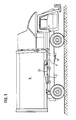
- the tilting frame 4 On the chassis 1 of the refuse collection vehicle 2, the tilting frame 4 is pivotally mounted about the non-visible transverse axis 3, which, due to the hydraulic pressure medium-piston-cylinder unit 5, lies between its position horizontally on the chassis 1 and its position perpendicular to the chassis, which can be seen from Figure 5, is pivotable.
- the container 6 is guided in a longitudinally displaceable manner in guides or by scenes on the tilting frame 4 and can be moved back and forth on the latter by a hydraulic piston-cylinder unit 7.
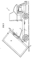
- the container 6 In order to set the container 6 down, it is first pushed on the tilting frame 4 from the position shown in FIG. 1 to the position shown in FIG. 2 so far back over the rear of the vehicle that the closure flap located in the front wall of the container closes can and when tilting the tipping frame 4 the lower front edge 9 of the container can swing past the packer without hindrance.
- the piston rod 32 is almost completely pushed out of the cylinder of the pressure medium piston-cylinder unit 7 in the retracted transport position of the container 6, while in the extended position of the container 6 shown in FIG .2 can be seen, almost completely inserted into the cylinder is.
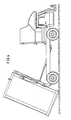
- the tilting frame 4 is tilted backwards via the pressure medium-piston-cylinder unit 5 until the rear lower edge 8 of the container 6 Touches the ground. Since the pressure medium-piston-cylinder unit 7 is switched to the floating position, the container 6 on the tilting frame 4 can be moved again towards its retracted position by further erecting the tilting frame 4 via the pressure medium-piston-cylinder unit 5. As soon as the rear lower edge 8 of the container 6 has touched the ground, the vehicle brake is released so that the vehicle 2 can roll according to the displacement of the container 6 on the tilting frame 4 in the direction of the retracted position.
- the tilting frame is in turn pivoted into its vertical position shown in FIG. 5, the locking device having been moved by the pressure medium-piston-cylinder unit 7 into a position which corresponds to the retracted position of the container.
- the tilt cylinders 5 are provided twice.
- the extension chambers 12 of the tilt cylinders 5 are connected to the hydraulic line 13 and the draw-in chambers 14 to the hydraulic line 15.
- the hydraulic lines 13, 15 lead to the directional control valve 16, which continues via the pressure line 17 to the pump 33 and to the tank Return line 18 is connected.
- the controllable check valve 24 is connected to the directional control valve 22 via a hydraulic line 25.
- the controllable check valve 24 can be unlocked via a control line 26 which is connected to the OR valve 27.
- the OR valve 27 is connected to the hydraulic line 15 by a control line 28 and to the hydraulic line 20 by a further control line 29.
- the directional control valve 22 moves in its positions a and b the piston rod 32 of the cylinder 7 back and forth, so that in the positions a and b the container on the tilting frame 4 can be retracted in the direction of the driver's cab and extended in the direction of the rear .
- the piston rod 32 of the cylinder 7 can be pulled out in the floating position, so that the container 6 can be moved in the direction of its retracted position, since the check valve 24 is acted upon in the passage direction.
- the extraction of the piston rod 32 from the cylinder 7 thus corresponds to the retracting movement of the container.
- the lowering movement of the container is blocked by the check valve 24, so that an unintentional slipping of the container with an inclined tilting frame is avoided with all the dangers that result.
- the piston rod 32 In position a of the directional control valve 22, the piston rod 32 can be pushed out and the container can be moved in the direction of the driver's cab on the tilting frame, since in this position the check valve is acted upon in the direction of passage.
- the OR valve is pressurized via the control line 28, so that the control line 26 also carries pressure and thereby the controllable check valve 24 unlocks. This unlocking is required if, in the floating position of the cylinder 7, the tilting frame has received a vertical container by coupling and this is to be tilted into its horizontal position on the chassis.
- the piston rod 32 is inserted into the cylinder in the position c of the directional valve 22.
- the hydraulic line 20 is pressurized, so that the control line 29 and the control line 26 are also pressurized and the check valve 24 is thereby unlocked.
- the hydraulic line 23 is connected to the return line 21.
- the cylinder 5 If the cylinder 5 is extended in the floating position of the piston-cylinder unit 7, the latter gives the tilting frame 4 an upright pivoting movement, with the check valve 24 preventing the container 6 from dropping unintentionally. After the container 6 has touched the ground, it pulls the refuse collection vehicle 2 to the rear.
- the floating position is effective because the check valve 24 is acted upon by the pressure medium in the passage direction.
- an unlocking device for the hand brake is expediently arranged in the area of the control station for the hydraulic control valves.
- a pulsatingly releasable brake with a spring brake cylinder can be provided, which permits a correspondingly tough controllable movement of the refuse collection vehicle.
- the locking device for coupling the slide that is displaceable on the tilting frame 4 to an eyelet 41 of the container 6.
- the locking device consists of a hook 2 which is provided with a tongue 43 which locks the eyelet 41 in the hook.
- the tongue 43 is pivotally mounted in the backdrop about a transverse axis 44. To pivot the tongue 43, it is provided with a projection 45 forming a lever, to which the piston rod 46 of a hydraulic piston-cylinder unit is articulated, the cylinder 47 of which is articulated on the link in the area of the foot of the hook 42.
- the piston rod 32 of the cylinder 7 is connected in an articulated manner to the backdrop that can be moved in guides via the connecting piece 48.
Landscapes
- Engineering & Computer Science (AREA)
- Transportation (AREA)
- Mechanical Engineering (AREA)
- Refuse-Collection Vehicles (AREA)
Abstract
Description
- Die Erfindung betrifft ein Müllsammelfahrzeug mit als Wechselbehälter ausgebildeten Containern, die jeweils mit einem Kipprahmen, der durch mindestens eine erste hydraulische Druckmittel-Kolben-Zylinder-Einheit relativ zu dem Hauptrahmen des Chassis um eine beide verbindende, am hinteren Endbereich beider Rahmen angeordnete Querachse schwenkbar ist, durch lösbare Kupplungseinrichtungen verbunden und die auf diesem Kipprahmen in Längsführungen oder auf einer Kulisse durch eine zweite hydraulische Druckmittel-Kolben-Zylinder-Einheit in Richtung zum Heck ausfahrbar oder in Richtung zum Fahrerhaus einfahrbar geführt sind, und mit einer die zweite hydraulische Druckmittel-Kolben-Zylinder-Einheit auf Schwimmstellung schaltenden Einrichtung.
- Bei einem aus der DE-OS 36 36 037 bekannten Fahrzeug dieser Art, bei dem es sich jedoch nicht speziell um ein Müllsammelfahrzeug handelt, wird die Steuerung des Aufnahme- und Absetzvorgangs eines Containers dadurch vereinfacht, daß zunächst der Container um ein vorbestimmtes Maß auf dem Kipprahmen über das Fahrzeugheck hinaus ausgefahren und anschließend der Kipprahmen durch Betätigung der ersten Druckmittel-Kolben-Zylinder-Einheiten gekippt wird, bis der untere Bereich des hinteren Endes des Behälters auf der Fahrbahnoberfläche aufliegt. Die den Container auf dem Hilfsrahmen verfahrende zweite Druckmittel-Kolben-Zylinder-Einheit wird sodann auf Schwimmstellung geschaltet, so daß der Kipprahmen ohne besondere Steuerung der zweiten Druckmittel-Kolben-Zylinder-Einheit durch den ersten Hydraulikzylinder in die Vertikale gekippt werden kann, in der er dann hochkant auf seiner hinteren Seite steht. Während des Kippens bis in die Vertikale läßt sich aufgrund der Schwimmschaltung der zweite Hydraulikzylinder in der erforderlichen Weise aus- oder einschieben. Bei dem bekannten Containerfahrzeug erfolgt das Aufnehmen des Containers in entsprechend umgekehrter Weise.
- Bei dem bekannten Containerfahrzeug besteht die Gefahr, daß der Container bei schräg stehendem Kipprahmen über das Heck des Fahrzeugs in unerwünschter Weise abrutschen kann, wenn die zweite Druckmittel-Kolben-Zylinder-Einheit auf Schwimmstellung geschaltet ist.
- Aufgabe der Erfindung ist es daher, ein Containerfahrzeug der eingangs angegeben Art zu schaffen, das mit einer Abrutschsicherung für den Container in der Schwimmstellung der zweiten Druckmittel-Kolben-Zylinder-Einheit versehen ist.
- Weiterhin soll die Möglichkeit geschaffen werden, den Container durch Bedienung nur eines Ventils unter Betätigung einer von außen zugänglichen Feststellbremse des Fahrzeugs ohne Verspannung der Absetzeinrichtungen abzusetzen.
- Erfindungsgemäß wird diese Aufgabe bei einem Containerfahrzeug der gattungsgemäßen Art dadurch gelöst, daß die zweite Druckmittel-Kolben-Zylinder-Einheit mit einem Wegeventil verbunden ist, das neben den Ein- und Ausfahrstellungen die Schwimmstellung aufweist, in der die zu den Zylinderkammern führenden Leitungen miteinander und mit der zum Tank führenden Rücklaufleitung verbunden sind, und daß in der zu der Ausfahrzylinderkammer führenden Leitung ein steuerbares Rückschlagventil angeordnet ist, das den Rückfluß von Druckmittel aus dieser sperrt und das durch Steuerleitungen überbrückbar ist, die dieses entsperren, wenn die den Container auf dem Hilfsrahmen verfahrende zweite Druckmittel-Kolben-Zylinder-Einheit in Ausfahrrichtung oder die den Hilfsrahmen verschwenkende Druckmittel-Kolben-Zylinder-Einheit in Einfahrrichtung mit Druckmittel beaufschlagt werden.
- Um einen Container von einem Container- oder Müllsammelfahrzeug nach der Erfindung abzusetzen und zu lösen, wird der Container auf den Kipprahmen, gegebenenfalls unter gleichzeitigem Aufrichten des Kipprahmens, so weit nach hinten verschoben, daß die Containerverschlußklappe, die zwischen dem Fahrerhaus und dem Container liegt, geschlossen und die vordere untere Kante des Containers behinderungsfrei an dem Fahrerhaus oder an dem Aufnahme- und Verdichtungsraum, dem sogenannten Packer, der hinter dem Fahrerhaus eines Müllsammelfahrzeugs angeordnet ist, vorbeischwenken kann. Ist der Container auf dem Kipprahmen durch die zweite Druckmittel-Kolben-Zylinder-Einheit so weit über das Heck hinaus gefahren worden, daß die hintere untere Kante des Containers bei einem weiteren Verschwenken des Kipprahmens in Aufstellrichtung die Fahrbahn oder den Boden berühren kann, kann die zweite Druckmittel-Kolben-Zylinder-Einheit auf Schwimmstellung geschaltet werden. In dieser Schwimmstellung verhindert das Rückschlagventil, daß der Container in unerwünschter Weise unter Schwerkraftwirkung abrutscht. Hat der Container mit seiner hinteren unteren Kante den Boden berührt, wird dieser auf dem Kipprahmen durch dessen weiteres Aufrichten in Einfahrrichtung verschoben. Da jedoch das Rückschlagventil in der Schwimm stellung die Einfahrbewegung freigibt, kann ein weiteres Aufrichten des Containers unter Zurückziehen des Fahrzeugs erfolgen. Um bei diesem weiteren Aufrichten ein Laufen des Fahrzeugs nach hinten zu ermöglichen, sind zuvor die Fahrzeugbremsen zu lösen.
- Soll nun ein in senkrechter Stellung bereitgestellter Container von dem Container- oder Müllsammelfahrzeug wieder aufgenommen werden, wird der senkrecht gestellte Kipprahmen mit in etwa ausgefahrener zweiter Druckmittel-Kolben-Zylinder-Einheit an diesen angekuppelt. Werden nun zum Kippen des Containers die ersten den Kipprahmen verschwenkenden Druckmittel-Kolben-Zylinder-Einheiten eingefahren, wird durch den Druck auf die Einfahrzylinderkammer oder Einfahrzylinderkammern das Rückschlagventil gelöst, so daß sich in der Schwimmstellung der zweiten Druckmittel-Kolben-Zylinder-Einheit der Container unter der Schwerkraftwirkung über das Heck ausziehen läßt. Die zweite Druckmittel-Kolben-Zylinder-Einheit wird dann von der Schwimmstellung über das Wegeventil auf die Ausfahrstellung geschaltet, wenn behinderungsfreies Einfahren des Containers in die Transportstellung auf dem Fahrzeug möglich ist.
- In weiterer Ausgestaltung der Erfindung ist vorgesehen, daß ein durch eine Steuerleitung mit der Ausfahrzylinderkammer der zweiten Druckmittel-Kolben-Zylinder-Einheit und durch eine weitere Steuerleitung mit der unter den Einfahrzylinderkammern der ersten Druckmittel-Kolben-Zylinder-Einheit verbundenes ODER-Ventil vorgesehen ist, das bei Druck auf einer der beiden Steuerleitungen das Rückschlagventil entsperrt. Diese Ausgestaltung führt zu einer einfachen Schaltungsanordnung, da über dasselbe ODER-Ventil das Rückschlagventil inaktiviert wird, wenn die zweite Druckmittel-Kolben-Zylinder-Einheit über das zugehörige Wegeventil auf Ausfahren geschaltet ist oder wenn in der Schwimmstellung der zweiten Druckmittel-Kolben-Zylinder-Einheit die Kippzylinder den Kipprahmen in Richtung auf den Hauptrahmen verschwenken.
- In weiterer Ausgestaltung der Erfindung ist vorgesehen, daß an dem außerhalb des Fahrerhauses befindlichen Steuerstand für die hydraulischen Ventile eine Betätigungseinrichtung für die Handbremse vorgesehen ist, mit der sich diese entriegeln und anziehen läßt. Erfindungsgemäß läßt sich also nach Bedarf mit entsprechender Betätigung der Ventile sogleich auch die Handbremse betätigen. Das erfindungsgemäße Müllsammelfahrzeug gestattet daher ein wesentlich vereinfachtes Absetzen des Containers. Weiterhin läßt sich dieser auch in vereinfachter Form wieder aufnehmen.
- Ein Ausführungsbeispiel der Erfindung wird nachstehend anhand der Zeichnung näher erläutert.
- In dieser zeigt
- Fig.1 ein Müllsammelfahrzeug mit Kipprahmen und auf diesem hin- und herverschieblich geführten Container in Seitenansicht,
- Fig.2 ein der Fig.1 entsprechende Darstellung des Müllsammelfahrzeugs mit nach hinten weiter über das Heck abgeschobenem Container,
- Fig.3 und Fig.4 unterschiedliche Stellungen des Kipprahmens und des Containers während des Absetzvorganges,
- Fig.5 den hochkant stehenden Container mit noch angekuppeltem Kipprahmen,
- Fig.6 die hydraulische Steuerung der Kipp- und Verschiebezylinder in schematischer Darstellung und
- Fig.7 eine Seitenansicht der Verriegelungsvorrichtung zur Verriegelung des Kipprahmens mit dem Container
- Auf dem Chassis 1 des Müllsammelfahrzeugs 2 ist um die nicht sichtbare Querachse 3 der Kipprahmen 4 schwenkbar gelagert, der durch die hydraulische Druckmittel-Kolben-Zylinder-Einheit 5 zwischen seiner waagerecht auf dem Chassis 1 liegenden Stellung und seiner senkrecht zu dem Chassis stehenden Stellung, die aus Fig.5 ersichtlich ist, verschwenkbar ist. Der Container 6 ist in Führungen oder durch Kulissen auf dem Kipprahmen 4 längsverschieblich geführt und auf diesem durch eine hydraulische Kolben-Zylinder-Einheit 7 hin- und herverfahrbar.
- Die Kolbenstange 32 der Druckmittel-Kolben-Zylinder-Einheit 7, die den Container 6 auf dem Kipprahmen 4 hin-und herverfährt ist in der Transportstellung des Containers 6, wenn der Container 6 mit dem Packer verriegelt ist, ausgefahren.
- Um den Container 6 abzusetzen, wird dieser auf dem Kipprahmen 4 zunächst aus der in Fig.1 ersichtlichen Stellung etwa in die aus Fig.2 ersichtliche Stellung so weit nach hinten weiter über das Fahrzeugheck hinausgeschoben, daß die in der Vorderwand des Containers befindliche Verschlußklappe geschlossen werden kann und beim Kippen des Kipprahmens 4 die untere vordere Kante 9 des Containers behinderungsfrei an dem Packer vorbeischwenken kann. Wie aus Fig. 1 ersichtlich ist, ist die Kolbenstange 32 in der eingefahrenen Transportstellung des Containers 6 nahezu vollständig aus dem Zylinder der Druckmittel-Kolben-Zylinder-Einheit 7 ausgeschoben, während sie in der nach hinten ausgefahrenen Stellung des Containers 6, die aus Fig.2 ersichtlich ist, nahezu vollständig in den Zylinder eingeschoben ist.
- Sobald der Container 6 auf dem Kipprahmen 4 in der aus Fig.2 ersichtlichen Weise nach hinten gefahren worden ist, wird der Kipprahmen 4 über die Druckmittel-Kolben-Zylinder-Einheit 5 nach hinten gekippt, bis die hintere untere Kante 8 des Containers 6 den Boden berührt. Da die Druckmittel-Kolben-Zylinder-Einheit 7 auf Schwimmstellung geschaltet ist, kann durch weiteres Aufrichten des Kipprahmens 4 über die Druckmittel-Kolben-Zylinder-Einheit 5 der Container 6 auf dem Kipprahmen 4 wieder in Richtung auf seine eingefahrene Stellung verschoben werden. Sobald die hintere untere Kante 8 des Containers 6 den Boden berührt hat, wird die Fahrzeugbremse gelöst, so daß entsprechend der Verschiebung des Containers 6 auf dem Kipprahmen 4 in Richtung auf die eingefahrene Stellung das Fahrzeug 2 nachrollen kann.
- Hat der Container 6 nach Kippen über die aus Fig .4 ersichtliche Stellung aus Fig. 5 ersichtliche senkrechte Stellung erreicht, wird die Verriegelung gelöst und das Müllsammelfahrzeug kann abgefahren werden.
- Zur Aufnahme eines Containers 6 wird der Kipprahmen wiederum in seine aus Fig.5 ersichtliche vertikale Stellung geschwenkt, wobei die Verriegelungseinrichtung durch die Druckmittel-Kolben-Zylinder-Einheit 7 etwa in eine Stellung verfahren worden ist, die der eingefahrenen Stellung des Containers entspricht.
- Wie aus Fig. 6 ersichtlich ist, sind die Kippzylinder 5 doppelt vorgesehen. Die Aussschubkammern 12 der Kippzylinder 5 sind mit der Hydraulikleitung 13 und die Einzugskammern 14 mit der Hydraulikleitung 15 verbunden. Die Hydraulikleitungen 13,15 führen zu dem Wegeventil 16, das weiterhin über die Druckleitung 17 mit der Pumpe 33 und der zu dem Tank führenden Rücklaufleitung 18 verbunden ist.
- Die Kammer 19 des Zylinders 7, bei deren Beaufschlagung mit Druck der Container in Ausfahrrichtung bewegt wird, ist über eine Hydraulikleitung 20 mit dem Steuerventil 22 verbunden, während die die Einfahrbewegung des Containers bewirkende Kammer 21 über eine Hydraulikleitung 23 mit dem steuerbaren Rückschlagventil 24 verbunden ist. Das steuerbare Rückschlagventil 24 ist über eine Hydraulikleitung 25 mit dem Wegeventil 22 verbunden. Das steuerbare Rückschlagventil 24 ist über eine Steuerleitung 26 entsperrbar, die mit dem ODER-Ventil 27 verbunden ist. Das ODER-Ventil 27 ist durch eine Steuerleitung 28 mit der Hydraulikleitung 15 und eine weitere Steuerleitung 29 mit der Hydraulikleitung 20 verbunden. Das Wegeventil 22 verschiebt in seinen Stellungen a und b die Kolbenstange 32 des Zylinders 7 hin und her, so daß sich in den Stellungen a und b der Container auf dem Kipprahmen 4 in Richtung auf das Fahrerhaus ein- und in Richtung über das Heck ausfahren läßt.
- In der Stellung b des Wegeventils 22 befindet sich der Zylinder 7 in seiner Schwimmstellung. In dieser Stellung sind die Leitungen 20,25 miteinander und mit der Rücklaufleitung 31 zum Tank verbunden.
- Wie aus Fig. 2 ersichtlich ist, läßt sich die Kolbenstange 32 des Zylinders 7 in der Schwimmstellung ausziehen, so daß der Container 6 in Richtung auf seine eingefahrene Stellung bewegt werden kann, da das Rückschlagventil 24 in Durchgangsrichtung beaufschlagt wird. Der Auszug der Kolbenstange 32 aus dem Zylinder 7 entspricht also der Einfahrbewegung des Containers. Hingegen ist durch das Rückschlagventil 24 die Absenkbewegung des Containers gesperrt, so daß ein unbeabsichtigtes Abrutschen des Containers bei schräg gestelltem Kipprahmen mit allen dadurch gegebenen Gefahren vermieden ist.
- In der Stellung a des Wegeventils 22 läßt sich die Kolbenstange 32 ausschieben und der Container in Richtung auf das Fahrerhaus auf dem Kipprahmen bewegen, da in dieser Stellung das Rückschlagventil in Durchgangsrichtung beaufschlagt wird.
- Wird während der Einzugsbewegung des Zylinders 5, also beim Absenken des Kipprahmens auf das Chassis die Hydraulikleitung 15 mit Druck beaufschlagt, wird über die Steuerleitung 28 das ODER-Ventil mit Druck beaufschlagt, so daß auch die Steuerleitung 26 Druck führt und dadurch das steuerbare Rückschlagventil 24 ensperrt. Diese Entsperrung ist erforderlich, wenn in der Schwimmstellung des Zylinders 7 der Kipprahmen einen senkrecht stehenden Container durch Ankuppeln aufgenommen hat und dieser in seine waagerechte Stellung auf dem Chassis gekippt werden soll.
- Wird der Container 6 weiter über das Heck ausgefahren, wird in der Stellung c des Wegeventils 22 die Kolbenstange 32 in den Zylinder eingeschoben. Während dieser Einschubbewegung der Kolbenstange 32 in den Zylinder 7 ist die Hydraulikleitung 20 mit Druck beaufschlagt, so daß auch die Steuerleitung 29 und die Steuerleitung 26 mit Druck beaufschlagt sind und dadurch das Rückschlagventil 24 entsperrt wird. In dieser Stellung ist die Hydraulikleitung 23 mit der Rücklaufleitung 21 verbunden.
- Wird also in der Schwimmstellung der Kolben-Zylinder-Einheit 7 der Zylinder 5 ausgefahren, erteilt dieser dem Kipprahmen 4 eine aufrichtende Schwenkbewegung, wobei ein ungewolltes Absinken des Containers 6 durch das Rückschlagventil 24 verhindert ist. Nach Berührung des Containers 6 mit dem Boden zieht dieser das Müllsammelfahrzeug 2 nach hinten. Die Schwimmstellung wird dabei wirksam, weil das Rückschlagventil 24 in Durchgangsrichtung von dem Druckmittel beaufschlagt wird.
- Um die Fahrzeugbremse im geeigneten Zeitpunkt lösen zu können, also wenn nach Einschalten der Schwimmstellung der Container mit seiner hinteren unteren Kante den Boden berührt hat, ist zweckmäßigerweise im Bereich des Steuerstandes für die hydraulischen Steuerventile eine Entriegelungseinrichtung für die Handbremse angeordnet. Es kann eine pulsierend lösbare Bremse mit einem Federspeicherbremszylinder vorgesehen sein, der eine entsprechend zähe kontrollierbare Bewegung des Müllsammelfahrzeugs zuläßt.
- Aus Fig.7 ist die Verriegelungseinrichtung 40 zum Ankuppeln der auf dem Kipprahmen 4 verschieblichen Kulisse an eine Öse 41 des Containers 6 ersichtlich. Die Verriegelungseinrichtung besteht aus einem Haken 2, der mit einer die Öse 41 in dem Haken verriegelnden Zunge 43 versehen ist. Die Zunge 43 ist in der Kulisse um eine Querachse 44 schwenkbar gelagert. Zum Verschwenken der Zunge 43 ist diese mit einem einen Hebel bildenden Vorsprung 45 versehen, an der die Kolbenstange 46 einer hydraulischen Kolben-Zylinder-Einheit angelenkt ist, deren Zylinder 47 gelenkig an der Kulisse im Bereich des Fußes des Hakens 42 gelagert ist. An die in Führungen verfahrbare Kulisse ist über das Anschlußstück 48 die Kolbenstange 32 des Zylinders 7 gelenkig angeschlossen.
Claims (3)
dadurch gekennzeichnet,
daß die zweite Druckmittel-Kolben-Zylinder-Einheit (7) mit einem Wegeventil (22) verbunden ist, das neben den Ein- und Ausfahrstellungen (a,c) für den Container die Schwimmstellung (b) aufweist, in der die zu den Zylinderkammern (19,21) führenden Leitungen (20,23,25) miteinander und mit der zum Tank führenden Rücklaufleitung verbunden sind, und daß in der zu der das Einfahren des Containers bewirkenden Zylinderkammer (21) führenden Leitung (23,25) ein steuerbares Rückschlagventil (24) angeordnet ist, das den Rückfluß von Druckmittel aus dieser sperrt und das durch Steuerleitungen überbrückbar ist, die dieses entsperren, wenn die den Container (6) auf dem Hilfsrahmen (4) verfahrende zweite Druckmittel-Kolben-Zylinder-Einheit (7) in Ausfahrrichtung des Containers oder die den Hilfsrahmen (4) verschwenkende Druckmittel-Kolben-Zylinder-Einheit (5) in Einfahrrichtung mit Druckmittel beaufschlagt werden.
Priority Applications (1)
| Application Number | Priority Date | Filing Date | Title |
|---|---|---|---|
| AT89110048T ATE88143T1 (de) | 1988-06-22 | 1989-06-02 | Muellsammelfahrzeug mit als wechselbehaelter ausgebildeten, auf einem kipprahmen hin- und herverschieblich gefuehrten containern. |
Applications Claiming Priority (4)
| Application Number | Priority Date | Filing Date | Title |
|---|---|---|---|
| DE3821094 | 1988-06-22 | ||
| DE3821094 | 1988-06-22 | ||
| DE3840246 | 1988-11-29 | ||
| DE3840246A DE3840246A1 (de) | 1988-06-22 | 1988-11-29 | Muellsammelfahrzeug mit als wechselbehaelter ausgebildeten, auf einem kipprahmen hin- und herverschieblich gefuehrten containern |
Publications (3)
| Publication Number | Publication Date |
|---|---|
| EP0347633A2 true EP0347633A2 (de) | 1989-12-27 |
| EP0347633A3 EP0347633A3 (en) | 1990-07-11 |
| EP0347633B1 EP0347633B1 (de) | 1993-04-14 |
Family
ID=25869351
Family Applications (1)
| Application Number | Title | Priority Date | Filing Date |
|---|---|---|---|
| EP89110048A Expired - Lifetime EP0347633B1 (de) | 1988-06-22 | 1989-06-02 | Müllsammelfahrzeug mit als Wechselbehälter ausgebildeten, auf einem Kipprahmen hin- und herverschieblich geführten Containern |
Country Status (4)
| Country | Link |
|---|---|
| US (1) | US5044861A (de) |
| EP (1) | EP0347633B1 (de) |
| DE (2) | DE3840246A1 (de) |
| ES (1) | ES2039751T3 (de) |
Cited By (3)
| Publication number | Priority date | Publication date | Assignee | Title |
|---|---|---|---|---|
| EP0414235A1 (de) * | 1989-08-23 | 1991-02-27 | EDELHOFF POLYTECHNIK GMBH & CO. | Lastkraftwagen zum Aufnehmen, Absetzen und Transport von mit diesem kuppelbaren Behältern, vorzugsweise Müllsammelfahrzeug mit Wechselbehältern |
| EP0795436A3 (de) * | 1996-03-15 | 2002-10-16 | FAUN Umwelttechnik GmbH & Co. | Fahrzeug, vorzugsweise Abfallsammelfahrzeug, mit als Wechselbehälter ausgebildeten Containern |
| CN112681435A (zh) * | 2020-12-21 | 2021-04-20 | 上海建工二建集团有限公司 | 用于逆作法取土口的取土装置及其安装方法 |
Families Citing this family (29)
| Publication number | Priority date | Publication date | Assignee | Title |
|---|---|---|---|---|
| DE4204062A1 (de) * | 1992-02-12 | 1993-08-19 | Edgar Georg | Fahrzeug zum aufnehmen und transportieren von abfallstoffen |
| RU2119883C1 (ru) * | 1992-02-12 | 1998-10-10 | Эдгар Георг | Транспортное средство для приема и транспортировки мусора |
| DE4412658C2 (de) * | 1994-04-13 | 1997-04-10 | Karl Mueller Gmbh & Co Kg Fahr | Fahrzeug zum Transport von Rollbehältern |
| US5562390A (en) * | 1995-01-24 | 1996-10-08 | Mcneilus Truck And Manufacturing, Inc. | Detachable truck body and handling mechanism |
| AU698069B2 (en) * | 1995-02-15 | 1998-10-22 | Mcneilus Truck And Manufacturing, Inc. | Multiple compartment body for waste materials |
| US6752467B1 (en) | 2002-02-14 | 2004-06-22 | Vac-Con, Inc. | Vacuum truck dump container apparatus |
| AU2003213129A1 (en) * | 2002-04-15 | 2003-11-03 | Boasso America Corporation (A Louisiana Corporation) | Method and apparatus for supplying bulk product to an end user |
| US6733027B2 (en) | 2002-06-19 | 2004-05-11 | Delaware Capital Formation, Inc. | Detachable truck body/semi trailer |
| DE10307346A1 (de) * | 2003-02-21 | 2004-09-02 | Deere & Company, Moline | Ventilanordnung |
| US20060072993A1 (en) * | 2004-10-04 | 2006-04-06 | Delaware Capital Formation, Inc. | Refuse collection system and method |
| US7278816B2 (en) * | 2004-12-23 | 2007-10-09 | Automated Waste Equipment Co., Inc. | Locking mechanism for a double articulating hook lift apparatus usable mounted on a vehicle |
| US20100071284A1 (en) * | 2008-09-22 | 2010-03-25 | Ed Hagan | Self Erecting Storage Unit |
| US20100282520A1 (en) * | 2009-05-05 | 2010-11-11 | Lucas Bruce C | System and Methods for Monitoring Multiple Storage Units |
| US20100329072A1 (en) * | 2009-06-30 | 2010-12-30 | Hagan Ed B | Methods and Systems for Integrated Material Processing |
| USRE46725E1 (en) | 2009-09-11 | 2018-02-20 | Halliburton Energy Services, Inc. | Electric or natural gas fired small footprint fracturing fluid blending and pumping equipment |
| US8834012B2 (en) * | 2009-09-11 | 2014-09-16 | Halliburton Energy Services, Inc. | Electric or natural gas fired small footprint fracturing fluid blending and pumping equipment |
| US8444312B2 (en) * | 2009-09-11 | 2013-05-21 | Halliburton Energy Services, Inc. | Methods and systems for integral blending and storage of materials |
| US8511150B2 (en) * | 2009-12-10 | 2013-08-20 | Halliburton Energy Services, Inc. | Methods and systems for determining process variables using location of center of gravity |
| US8354602B2 (en) * | 2010-01-21 | 2013-01-15 | Halliburton Energy Services, Inc. | Method and system for weighting material storage units based on current output from one or more load sensors |
| WO2012069985A2 (en) * | 2010-11-22 | 2012-05-31 | Groupe Environnemental Labrie Inc. | Box lifting assembly for dump trucks or similar vehicles |
| CN102285331A (zh) * | 2011-06-28 | 2011-12-21 | 三一重工股份有限公司 | 一种用于车辆的自动装卸装置及自动装卸车辆 |
| CN102381230A (zh) * | 2011-08-23 | 2012-03-21 | 三一重工股份有限公司 | 一种背罐车及其液压系统 |
| CA2963102C (en) | 2011-10-24 | 2018-08-21 | Solaris Oilfield Site Services Operating Llc | Fracture sand silo system and methods of deployment and retraction of same |
| US10300830B2 (en) | 2011-10-24 | 2019-05-28 | Solaris Oilfield Site Services Operating Llc | Storage and blending system for multi-component granular compositions |
| US10836568B2 (en) | 2011-10-24 | 2020-11-17 | Solaris Oilfield Site Services Operating Llc | Blender hopper control system for multi-component granular compositions |
| JP5963768B2 (ja) | 2011-11-14 | 2016-08-03 | 日立建機株式会社 | 運搬車両 |
| US9227546B2 (en) | 2012-05-01 | 2016-01-05 | Omaha Standard, Llc | Hook lift jib apparatus |
| CN102673800B (zh) * | 2012-06-04 | 2014-03-26 | 航天晨光股份有限公司 | 一种油罐加油车 |
| CN104553930B (zh) * | 2013-10-24 | 2017-09-15 | 重庆妙坤生物科技有限责任公司 | 一种翻斗货车 |
Family Cites Families (10)
| Publication number | Priority date | Publication date | Assignee | Title |
|---|---|---|---|---|
| US1985169A (en) * | 1932-04-27 | 1934-12-18 | Howell Ind Truck Company | Industrial truck |
| US3071926A (en) * | 1960-04-12 | 1963-01-08 | Hyster Co | Hydraulic lift cylinder circuit |
| US3399795A (en) * | 1966-08-15 | 1968-09-03 | Harsco Corp | Loading apparatus for demountable vehicle bodies |
| US3462033A (en) * | 1966-10-20 | 1969-08-19 | Kysor Industrial Corp | Dumping vehicle with detachable body mechanism |
| US3857504A (en) * | 1972-03-31 | 1974-12-31 | Sanitary Controls Inc | Mechanism for locking refuse container on truck platform |
| JPS56131435A (en) * | 1980-03-17 | 1981-10-15 | Kanto Tokushiya Hanbai Kk | Device for moving and tilting bed of autotruck |
| DE3332275C2 (de) * | 1983-09-07 | 1999-06-02 | Meiller Fahrzeuge | Fahrzeug mit einer Abrollkippeinrichtung |
| DE3526209A1 (de) * | 1985-07-23 | 1987-01-29 | Weyhausen Gmbh & Co Kg Maschin | Transportfahrzeug zum aufladen, abladen und transportieren von behaeltern |
| DE3636037A1 (de) * | 1986-10-23 | 1988-04-28 | Bock Norman | Verfahren zum aufnehmen und absetzen eines hohl-behaelters, wie silo, container oder dergleichen, auf bzw. von einem fahrzeug mit wechselgeraet, wechselgeraet zur durchfuehrung des verfahrens sowie bei der durchfuehrung des verfahrens verwendbarer behaelter |
| DE3708066A1 (de) * | 1987-03-13 | 1988-09-29 | Josef Paul | Nutzfahrzeug mit wechselaufbau |
-
1988
- 1988-11-29 DE DE3840246A patent/DE3840246A1/de active Granted
-
1989
- 1989-06-02 DE DE8989110048T patent/DE58904046D1/de not_active Expired - Fee Related
- 1989-06-02 ES ES198989110048T patent/ES2039751T3/es not_active Expired - Lifetime
- 1989-06-02 EP EP89110048A patent/EP0347633B1/de not_active Expired - Lifetime
-
1990
- 1990-10-31 US US07/607,202 patent/US5044861A/en not_active Expired - Fee Related
Cited By (3)
| Publication number | Priority date | Publication date | Assignee | Title |
|---|---|---|---|---|
| EP0414235A1 (de) * | 1989-08-23 | 1991-02-27 | EDELHOFF POLYTECHNIK GMBH & CO. | Lastkraftwagen zum Aufnehmen, Absetzen und Transport von mit diesem kuppelbaren Behältern, vorzugsweise Müllsammelfahrzeug mit Wechselbehältern |
| EP0795436A3 (de) * | 1996-03-15 | 2002-10-16 | FAUN Umwelttechnik GmbH & Co. | Fahrzeug, vorzugsweise Abfallsammelfahrzeug, mit als Wechselbehälter ausgebildeten Containern |
| CN112681435A (zh) * | 2020-12-21 | 2021-04-20 | 上海建工二建集团有限公司 | 用于逆作法取土口的取土装置及其安装方法 |
Also Published As
| Publication number | Publication date |
|---|---|
| US5044861A (en) | 1991-09-03 |
| DE3840246C2 (de) | 1991-10-17 |
| DE3840246A1 (de) | 1990-01-04 |
| EP0347633A3 (en) | 1990-07-11 |
| DE58904046D1 (de) | 1993-05-19 |
| EP0347633B1 (de) | 1993-04-14 |
| ES2039751T3 (es) | 1993-10-01 |
Similar Documents
| Publication | Publication Date | Title |
|---|---|---|
| EP0347633B1 (de) | Müllsammelfahrzeug mit als Wechselbehälter ausgebildeten, auf einem Kipprahmen hin- und herverschieblich geführten Containern | |
| EP0264925B2 (de) | Verfahren zum Aufnehmen und Absetzen eines Hohl-Behälters, wie Silo, Container oder dergleichen, auf bzw. von einem Fahrzeug mit Wechselgerät, Wechselgerät zur Durchführung des Verfahrens sowie bei der Durchführung des Verfahrens verwendbarer Behälter | |
| DE2420603A1 (de) | Mechanisches wechselsystem fuer abstellbare aufbauten von lastkraftwagen, anhaengern oder sattelaufliegern | |
| DE8910746U1 (de) | Zustiegsvorrichtung für Kraftfahrzeuge, insbesondere für Omnibusse | |
| DE3923695C2 (de) | Vorrichtung zum Niederholen des vorderen Endes eines Fahrzeugverdecks | |
| DE3707215A1 (de) | Verfahren und vorrichtung zum ausfahren eines frei auskragenden endbereichs eines kranauslegers | |
| DE3501107C2 (de) | ||
| DE2352991A1 (de) | Hebegeraet | |
| DE19637891A1 (de) | Vorrichtung zum Hinaufziehen und Absetzen eines Behälters auf bzw. von einem Aufbau eines Lastentransportfahrzeugs | |
| DE2524584C2 (de) | ||
| DE19957499A1 (de) | Durchladbarer Gliederzug, insbesondere zum Transport von Lebensmitteln | |
| DE2347691A1 (de) | Vorrichtung zum laden und abladen von containern | |
| EP0794086B1 (de) | Lastfahrzeug mit einer Einrichtung zum Be- und Entladen eines Behälters | |
| DE822476C (de) | Kippvorrichtung fuer die Ladebuehne von Mehrseitenkippern, insbesondere von Anhaengern | |
| DE4240125A1 (de) | Hydraulische Absetzeinrichtung für Wechselaufbauten | |
| AT334220B (de) | Mechanisches wechselsystem fur abstellbare aufbauten von lastkraftwagen, anhangern oder sattelaufliegern | |
| DE29604355U1 (de) | Vorrichtung zum Hinaufziehen und Absetzen eines Behälters auf bzw. von einem Aufbau eines Lastentransportfahrzeugs | |
| DE2660637C2 (de) | Transportgeraet, bestehend aus einem austaschbaren behaelter und einem transportfahrzeug | |
| DE29604947U1 (de) | Einrichtung an einem Fahrzeug zum Aufnehmen und Absetzen von Wechselaufbauten | |
| EP4489995B1 (de) | Anhebe- und absenkanordnung für containerverriegelung und anhebe- und absenkverfahren damit | |
| DE3049507A1 (de) | Transportfahrzeug mit schiebeverriegelbarem wechselaufbau | |
| DE4004960A1 (de) | Vorrichtung an einer ladebordwand | |
| DE9317545U1 (de) | Schwenkbare Bordwand eines Transportfahrzeugs | |
| CH579470A5 (de) | ||
| DE1923774A1 (de) | Fahrzeug,insbesondere landwirtschaftliches Fahrzeug |
Legal Events
| Date | Code | Title | Description |
|---|---|---|---|
| PUAI | Public reference made under article 153(3) epc to a published international application that has entered the european phase |
Free format text: ORIGINAL CODE: 0009012 |
|
| AK | Designated contracting states |
Kind code of ref document: A2 Designated state(s): AT BE CH DE ES FR GB IT LI LU NL SE |
|
| PUAL | Search report despatched |
Free format text: ORIGINAL CODE: 0009013 |
|
| AK | Designated contracting states |
Kind code of ref document: A3 Designated state(s): AT BE CH DE ES FR GB IT LI LU NL SE |
|
| 17P | Request for examination filed |
Effective date: 19900627 |
|
| 17Q | First examination report despatched |
Effective date: 19911230 |
|
| GRAA | (expected) grant |
Free format text: ORIGINAL CODE: 0009210 |
|
| AK | Designated contracting states |
Kind code of ref document: B1 Designated state(s): AT BE CH DE ES FR GB IT LI LU NL SE |
|
| PG25 | Lapsed in a contracting state [announced via postgrant information from national office to epo] |
Ref country code: SE Effective date: 19930414 |
|
| REF | Corresponds to: |
Ref document number: 88143 Country of ref document: AT Date of ref document: 19930415 Kind code of ref document: T |
|
| REF | Corresponds to: |
Ref document number: 58904046 Country of ref document: DE Date of ref document: 19930519 |
|
| GBT | Gb: translation of ep patent filed (gb section 77(6)(a)/1977) |
Effective date: 19930426 |
|
| ITF | It: translation for a ep patent filed | ||
| PG25 | Lapsed in a contracting state [announced via postgrant information from national office to epo] |
Ref country code: AT Effective date: 19930602 |
|
| PG25 | Lapsed in a contracting state [announced via postgrant information from national office to epo] |
Ref country code: LU Free format text: LAPSE BECAUSE OF NON-PAYMENT OF DUE FEES Effective date: 19930630 Ref country code: LI Effective date: 19930630 Ref country code: CH Effective date: 19930630 |
|
| ET | Fr: translation filed | ||
| REG | Reference to a national code |
Ref country code: ES Ref legal event code: FG2A Ref document number: 2039751 Country of ref document: ES Kind code of ref document: T3 |
|
| PLBE | No opposition filed within time limit |
Free format text: ORIGINAL CODE: 0009261 |
|
| STAA | Information on the status of an ep patent application or granted ep patent |
Free format text: STATUS: NO OPPOSITION FILED WITHIN TIME LIMIT |
|
| REG | Reference to a national code |
Ref country code: CH Ref legal event code: PL |
|
| 26N | No opposition filed | ||
| REG | Reference to a national code |
Ref country code: GB Ref legal event code: IF02 |
|
| PGFP | Annual fee paid to national office [announced via postgrant information from national office to epo] |
Ref country code: ES Payment date: 20020625 Year of fee payment: 14 |
|
| PG25 | Lapsed in a contracting state [announced via postgrant information from national office to epo] |
Ref country code: ES Free format text: LAPSE BECAUSE OF NON-PAYMENT OF DUE FEES Effective date: 20030603 |
|
| REG | Reference to a national code |
Ref country code: ES Ref legal event code: FD2A Effective date: 20030603 |
|
| PGFP | Annual fee paid to national office [announced via postgrant information from national office to epo] |
Ref country code: GB Payment date: 20050519 Year of fee payment: 17 |
|
| PGFP | Annual fee paid to national office [announced via postgrant information from national office to epo] |
Ref country code: DE Payment date: 20050601 Year of fee payment: 17 |
|
| PGFP | Annual fee paid to national office [announced via postgrant information from national office to epo] |
Ref country code: NL Payment date: 20050620 Year of fee payment: 17 |
|
| PGFP | Annual fee paid to national office [announced via postgrant information from national office to epo] |
Ref country code: FR Payment date: 20050621 Year of fee payment: 17 |
|
| PGFP | Annual fee paid to national office [announced via postgrant information from national office to epo] |
Ref country code: BE Payment date: 20050623 Year of fee payment: 17 |
|
| PG25 | Lapsed in a contracting state [announced via postgrant information from national office to epo] |
Ref country code: GB Free format text: LAPSE BECAUSE OF NON-PAYMENT OF DUE FEES Effective date: 20060602 |
|
| PG25 | Lapsed in a contracting state [announced via postgrant information from national office to epo] |
Ref country code: BE Free format text: LAPSE BECAUSE OF NON-PAYMENT OF DUE FEES Effective date: 20060630 |
|
| PGFP | Annual fee paid to national office [announced via postgrant information from national office to epo] |
Ref country code: IT Payment date: 20060630 Year of fee payment: 18 |
|
| PG25 | Lapsed in a contracting state [announced via postgrant information from national office to epo] |
Ref country code: NL Free format text: LAPSE BECAUSE OF NON-PAYMENT OF DUE FEES Effective date: 20070101 |
|
| PG25 | Lapsed in a contracting state [announced via postgrant information from national office to epo] |
Ref country code: DE Free format text: LAPSE BECAUSE OF NON-PAYMENT OF DUE FEES Effective date: 20070103 |
|
| GBPC | Gb: european patent ceased through non-payment of renewal fee |
Effective date: 20060602 |
|
| NLV4 | Nl: lapsed or anulled due to non-payment of the annual fee |
Effective date: 20070101 |
|
| REG | Reference to a national code |
Ref country code: FR Ref legal event code: ST Effective date: 20070228 |
|
| BERE | Be: lapsed |
Owner name: *EDELHOFF POLYTECHNIK G.M.B.H. & CO. Effective date: 20060630 |
|
| PG25 | Lapsed in a contracting state [announced via postgrant information from national office to epo] |
Ref country code: FR Free format text: LAPSE BECAUSE OF NON-PAYMENT OF DUE FEES Effective date: 20060630 |
|
| PG25 | Lapsed in a contracting state [announced via postgrant information from national office to epo] |
Ref country code: IT Free format text: LAPSE BECAUSE OF NON-PAYMENT OF DUE FEES Effective date: 20070602 |