EP0346586B1 - Dispositif de contrôle pour presse à balles - Google Patents
Dispositif de contrôle pour presse à balles Download PDFInfo
- Publication number
- EP0346586B1 EP0346586B1 EP89106722A EP89106722A EP0346586B1 EP 0346586 B1 EP0346586 B1 EP 0346586B1 EP 89106722 A EP89106722 A EP 89106722A EP 89106722 A EP89106722 A EP 89106722A EP 0346586 B1 EP0346586 B1 EP 0346586B1
- Authority
- EP
- European Patent Office
- Prior art keywords
- signal
- fed
- signals
- baler according
- plunger
- Prior art date
- Legal status (The legal status is an assumption and is not a legal conclusion. Google has not performed a legal analysis and makes no representation as to the accuracy of the status listed.)
- Expired - Lifetime
Links
- 239000010902 straw Substances 0.000 title description 12
- 239000000463 material Substances 0.000 claims description 5
- 238000005259 measurement Methods 0.000 claims description 4
- 230000006835 compression Effects 0.000 claims 13
- 238000007906 compression Methods 0.000 claims 13
- 230000007257 malfunction Effects 0.000 claims 3
- 230000005540 biological transmission Effects 0.000 claims 2
- 230000001960 triggered effect Effects 0.000 claims 2
- 238000012937 correction Methods 0.000 description 4
- 238000010586 diagram Methods 0.000 description 4
- 238000012544 monitoring process Methods 0.000 description 4
- 230000006870 function Effects 0.000 description 2
- 230000001939 inductive effect Effects 0.000 description 2
- 238000010521 absorption reaction Methods 0.000 description 1
- 230000015572 biosynthetic process Effects 0.000 description 1
- 239000002131 composite material Substances 0.000 description 1
- 230000001143 conditioned effect Effects 0.000 description 1
- 230000001276 controlling effect Effects 0.000 description 1
- 230000001419 dependent effect Effects 0.000 description 1
- 238000001514 detection method Methods 0.000 description 1
- 230000000694 effects Effects 0.000 description 1
- 230000015654 memory Effects 0.000 description 1
- 230000001105 regulatory effect Effects 0.000 description 1
- 230000004044 response Effects 0.000 description 1
Images


Classifications
-
- B—PERFORMING OPERATIONS; TRANSPORTING
- B30—PRESSES
- B30B—PRESSES IN GENERAL
- B30B9/00—Presses specially adapted for particular purposes
- B30B9/30—Presses specially adapted for particular purposes for baling; Compression boxes therefor
- B30B9/3003—Details
- B30B9/3007—Control arrangements
-
- A—HUMAN NECESSITIES
- A01—AGRICULTURE; FORESTRY; ANIMAL HUSBANDRY; HUNTING; TRAPPING; FISHING
- A01F—PROCESSING OF HARVESTED PRODUCE; HAY OR STRAW PRESSES; DEVICES FOR STORING AGRICULTURAL OR HORTICULTURAL PRODUCE
- A01F15/00—Baling presses for straw, hay or the like
- A01F15/08—Details
- A01F15/0825—Regulating or controlling density or shape of the bale
-
- B—PERFORMING OPERATIONS; TRANSPORTING
- B30—PRESSES
- B30B—PRESSES IN GENERAL
- B30B9/00—Presses specially adapted for particular purposes
- B30B9/30—Presses specially adapted for particular purposes for baling; Compression boxes therefor
- B30B9/3003—Details
- B30B9/3025—Extrusion chambers with adjustable outlet opening
Definitions
- the invention relates to a baler with a regulating device and with a baling channel controllable in its baling channel resistance, which can be fed with pressed material from an elevator arranged on the front and in which an axially reciprocating baling piston is arranged on the front of an eccentric gear which is driven by a PTO shaft from one Motor of a towing vehicle is drivable, and a sensor is used to supply a signal indicating the respective pressing pressure to the control device, namely a summer, which is also supplied with a set signal of reversed polarity from a set point generator and the output signal of which acts on hydraulic control means of the controllable press channel in such a way that each the higher the measured baling pressure, the lower the baling channel resistance is controlled.
- a mobile baler which has a baling channel for straw bales, which is loaded with straw or other baling material from below with a full-width front elevator and in the front of which a baling piston periodically in the axial direction via an eccentric gear is pushed in and pressed in, the eccentric driving force being transmitted from the towing vehicle engine to the eccentric via a power take-off shaft and a counterforce to the pressing force of the piston on the straw bales in the pressing channel as a frictional force caused by wall-side braking surfaces.
- These braking surfaces can be adjusted by hydraulic adjusting means so that the effective channel cross section and thus the pressing force can be changed.
- the positioning means are from a Actuated control device, the actual variable is derived from the torque that occurs at the PTO, so that an approximately constant driving force is achieved.
- this leads to a lower pressing force being achieved at high speeds and high driving speeds due to the higher friction and mass forces, which results in looser, lighter bales.
- a straw baler of this type is known, in the connecting rods of the baling ram drive, which are arranged in pairs, a baling pressure sensor is arranged, the output signals of which are processed in a signal processing device with regard to their peak values, so that the difference in size and direction to the driver of the towing vehicle Display is made so that straw can be picked up evenly across the press width by suitable steering of the vehicle.
- this requires constant attention from the driver, and the driver's response time may cause large fluctuations in time.
- the press can be loaded too one-sided, causing skewing and, in extreme cases, jamming of the plunger.
- the signal acquisition on the moving connecting rod bearings is complex and prone to failure. A possible piston tilt is also not signaled immediately; the pressure values and differences occurring at the bearings only give an indirect indication of a tilt.
- the senor is at least one position sensor, which is arranged with respect to an abutment support of the eccentric gear on the baler that it signals a respective change in position of the abutment support as a result of a respective pressing pressure.
- two position sensors are arranged in relation to the abutment of the eccentric gear in such a way that their signals indicate both the pressing force and the symmetrical position of the pressing piston.
- the signals for controlling the baling channel resistance are therefore evaluated both with regard to the baling force and, moreover, with regard to the exceeding of a baling force threshold value and with regard to threshold violations of a symmetry deviation of the baling ram position on one side or the other.
- Exceeding the threshold nonlinearly causes an immediate expansion of the press channel.
- a limit value monitoring of the signal components with respect to limit values above the mentioned threshold values is advantageously carried out continuously, the alarm signal occurring in the event of the limit value being exceeded is used for an immediate drive decoupling.
- the measurement signals pulse periodically with the piston movement, they are advantageously processed by temporarily storing their peak values with a time constant that corresponds to the duration of several pressing cycles.
- the position sensors can be arranged such that they immediately signal the elastic deflection of an abutment support of the eccentric gear, or elastic bearing elements can be arranged on both sides of the abutment support, which in each case provides a relatively larger measuring path under a given load.
- Inductive, non-contact distance sensors can advantageously be used as position sensors. Your measurement signals are evaluated in each case with regard to a state without drive and pressing force. A zero point calibration is therefore carried out automatically.
- a further advantageous alternative position sensor arrangement consists in that position sensors are arranged opposite one another on the side of the plunger, by means of which the symmetrical positional deviation of the plunger is monitored and measured.
- the difference signal of the sensor signals gives the symmetry deviation of the plunger to the position of the two sensors without further calibration with respect to an initial position.
- the symmetry monitoring also provides monitoring of the bearing clearances of the highly loaded eccentric and connecting rod bearings.
- the difference signal obtained from the two processed baling pressure signals and / or from the processed symmetry monitoring signals is advantageously used to control the drawbar of the baler with respect to the towing vehicle, so that regulation for minimization of the differential signal and thus a symmetrical loading of the press.
- a hydraulic actuator is arranged on the drawbar.
- the driver can be given a visible display of the actuating signal which corresponds to the residual difference signal, so that the driver can maintain a counteracting middle course.
- an alarm display is provided in the event of limit value violations and inadmissible deviations from the piston symmetry position.
- the press pressure is displayed to the driver and / or is used to regulate the driving speed relative to the piston movement, so that optimum press performance utilization, in particular with different straw bearing densities, is achieved.
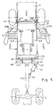
- Fig. 1 shows schematically a vertical section through the front area of a mobile straw baler (1).
- the straw (10) is conveyed via the elevator (11) into the baling channel (12), in which the baling ram (13) is moved axially back and forth via an eccentric gear (14) and continuously produces baling balls (10B) emerging from the rear.
- the eccentric gear (14) is driven by a towing vehicle articulated with a drawbar (15A) via a PTO shaft (15) with a worm gear (16).
- the eccentric gear (14) is supported on the side walls (18) with abutment supports (17, 17A) which extend into the press channel (12).
- Brake flaps (12A, 12B) project on all sides into the press channel (12) and can be pivoted with a hydraulic actuating cylinder (20) so that the press channel resistance can be controlled in a controllable manner.
- An inductive position sensor (21) is arranged on the front wall (19) with respect to the abutment support (17), so that its output signal signals a deflection of the abutment support (17) which is caused by the support of the eccentric gear (14) and thus that of the plunger (13 ) via the connecting rods (14P) of the eccentric gear indicates the pressing force transmitted.
- Fig. 2 shows a simplified, open plan view of Fig. 1, wherein the plunger (13) is in a position in which the eccentric is in its pressing dead center position, in which the abutment support (17) in the dash-dotted form (17D ) is bent.
- the position sensor (21) which is attached to the center of the fixed front wall (19), detects this deflection.
- Fig. 3 shows a block diagram which includes the complete control circuit of the pressing force.
- the measurement signal of the Position sensor (21) is supplied on the one hand to a linear amplifier (22) and on the other hand to a threshold value discriminator (27).
- the output signal of the linear amplifier (22) is fed to a peak rectifier (23) with a time constant (T1), each of which comprises several signal periods, and is thereby smoothed and fed to a summer (25) together with a setpoint signal from a setpoint generator (24).
- T1 time constant
- the difference formed is fed as a control signal to a hydraulic valve (26), the oil pressure of which acts on the actuating cylinder (20).
- the threshold value discriminator (27) only emits a non-zero output signal of a predefined size if a predefined threshold value (SW) is exceeded by the sensor signal.
- the output signal then occurring is stored in the peak rectifier (28) with a time constant (T2) which is sufficiently dimensioned that the press flaps (12A, 12B) can open fully if they were in their narrowest position. This provides effective overload protection, which enables the operator to continue working without intervention.
- a limit value discriminator (30) which compares the sensor signal with a limit value (GW) which lies above the threshold value (SW) of the threshold value discriminator (27).
- the output signal of the limit discriminator (30) sets each time a bistable flip-flop (31) is exceeded, the output signal of which releases a drive clutch (32) of the PTO shaft and acts on an alarm signal generator (33).
- the flip-flop (31) can be reset by the operator using an erase contact (34).
- the output signal of the threshold value discriminator (27) smoothed by the timing element (28) is sent as a warning signal to a further display (35).
- a resistance display (WA) of the press channel is advantageously provided in that the summing signal is displayed.
- the driver thus has the possibility of achieving an optimal utilization of the press by adapting the relative driving speed by providing a predetermined pressing pressure with a largely open pressing channel through a suitable gear selection. It is also possible to automatically actuate the gear shift (GS) of the vehicle by supplying an actuating signal to the gear shift (GS) from the summer (25) in such a way that a higher gear is selected, the higher the baling resistance is controlled . d. H. the lower the pressure is.
- Fig. 4 shows a cross section through the press channel (12). Its walls are designed as mutually pivotable brake flaps (12A-12D) and are articulated to one another at the corner points of their composite frame (32, 33, 34, 35) by inserting one of two legs of angle lever corner pieces (30, 31). The ends of the hydraulic actuator (20) of a cylinder-piston arrangement are articulated on the two free legs of the angle lever pieces (30, 31). When the same is applied, the channel cross section is narrowed on all sides.
- FIG. 5 shows an open plan view of a further embodiment in which two position sensors (210, 211) are arranged symmetrically to the central axis with respect to the abutment support (170).
- Your position difference signal is indirectly a measure of the deviation of the piston (13) from the central axis of symmetry and thus from the side change sections (120A, 120B) in the piston movement range.
- the abutment support (170) is advantageously mounted on both sides via elastic support elements (40, 41) on the front wall (190), so that the position sensors (210, 211), which are mounted in the front wall, signal their pressure.
- piston position sensors (42, 43) are arranged in the side wall sections (120A, 120B) with respect to the piston (13), so that their difference signal immediately signals a lateral deviation of the press piston (13) from the symmetrical position.
- the height of the individual signal directly indicates the proximity of the plunger (13) to the wall in which the respective position sensor (42, 43) is arranged.
- the baler (1) is connected to the towing vehicle (5) via the handlebar (15A) so that its travel path determines the travel path of the baler (1) while taking the cornering curve into cornering and thus for the absorption of the swaths of the elevator (11) , which extends below and on both sides of the press channel (12), is decisive.
- a symmetrical load control is advantageously provided to relieve the driver, for which purpose a steering actuator (44) is arranged on the handlebar (15A) by a hydraulic cylinder (44) is articulated in a bearing (46) to the handlebar (15A) and, on the other hand, it is connected to the front side (45) of the baler (1) is articulated to the side of the handlebar (15A).
- a steering actuator (44) is arranged on the handlebar (15A) by a hydraulic cylinder (44) is articulated in a bearing (46) to the handlebar (15A) and, on the other hand, it is connected to the front side (45) of the baler (1) is articulated to the side of the handlebar (15A).
- an action on the hydraulic cylinder (44) leads to a corresponding offset of the axles of the towing vehicle (5) and the baler (1).
- the hydraulic cylinder (44), the handlebar (15A) and the chassis of the press (1) form an approximately horizontal triangular joint.
- Fig. 6 shows a block diagram on the basis of which the linkage of the position sensors (210, 211; 42, 43) and the actuators (20, 44) is shown in control loops with the feedback (R1, R2).
- the pressure signals of the position sensors (210, 211), which indicate the piston pressing force on both sides, as well as the piston position signals of the position sensors (42, 43), which signal the lateral piston position on both sides, are processed in their respective peak value memories (S1, - S4), whose discharge time constant (T1) is several piston movement cycles.
- the conditioned pressure signals are added in the summer (AS1) and compared with a setpoint signal from a setpoint generator (SG).
- the comparison result signal is fed to a hydraulic valve arrangement (26) which continuously converts this signal into a hydraulic actuating signal which is fed to the actuating cylinder (20) on the press channel.
- the changeable pressing resistance of the press channel acts on the piston and thereby on the position sensors (210, 211), so that there is a first feedback path (R1).
- the processed pressure signals are also fed to a maximum value circuit (MS1), which in each case emits the highest of the incoming signals as a maximum value signal, which is compared in a first threshold value discriminator (SD1) with a first threshold value (SW1), if this is exceeded, a one signal is also added outputs to the summing circuit (AS1), so that its control signal causes an expansion of the press channel to its largest cross-section and smallest press resistance.
- MS1 maximum value circuit
- SD1 first threshold value discriminator
- SW1 first threshold value
- AS1 summing circuit
- the maximum value signal of the maximum value generator (MS1) is also compared in a first limit value discriminator (GD1) with a first limit value (GW1), if exceeded, the limit value discriminator (GW1) energizes an alarm display (33) and sets a fault flip-flop (31), the so set a release clutch (32) of the power take-off.
- the fault flip-flop (31) can be reset with a clear contact (34) after the fault has been remedied, so that the PTO drive can be engaged again.
- a steering control function is shown.
- the processed pressure signals are fed to a differential generator (D1), so that a differential signal is generated at its output, which indicates the asymmetrical loading of the piston.
- This signal is fed to an electro-hydraulic converter, a hydraulic four-way valve (VV) which controls the hydraulic steering cylinder (44) on the output side and is connected on the input side to a hydraulic supply and return line (HV, HR), so that a differential signal appropriate course correction is effected via a handlebar deflection.
- VV hydraulic four-way valve
- the difference signal of the difference generator (D1) is also fed directly and via an inverter (I) to a threshold value discriminator (SAR, SAL) and compared there with respect to a steering threshold value (SL), when exceeded, a right-hand or left-hand drive display (AR , AL) is actuated, which gives the driver correction information for large rule corrections.
- a threshold value discriminator SAR, SAL
- SL steering threshold value
- AR , AL right-hand or left-hand drive display
- the difference signal from the difference generator (D1) is furthermore advantageously fed directly and inverted via a second maximum value circuit (MS2) to a second limit value discriminator (GD2), which compares it with a predetermined second limit value (GW2) and controls an alarm signal generator (LA) if the latter is exceeded. that alerts the driver to a necessary steering correction.
- MS2 second maximum value circuit
- GD2 second limit value discriminator
- LA alarm signal generator
- a supplementary advantageous embodiment of the circuit consists in that the processed signals from the piston position sensors (42, 43) are fed to the maximum value circuit (MS1), so that the press channel is opened even if there is a large lateral deviation of the press piston and if the specified limit value ( GW1) the alarm signal is given and the fault flip-flop (31) is set.
- the prepared piston position signals can alternatively be sent from the designated points (X1, X2), i.e. be led to the inputs (X10, X11) of the difference generator (D1) so that their difference effects the steering control.
- the gear shift (GS) and the resistance display (WA) are controlled with the signal of the summer (AS1) in accordance with the example in FIG. 3.
- 3 and 6 can also be implemented by means of a microprocessor, in that the signals from the position sensors (21; 210, 211; 42, 43) are expertly routed to a controllable measuring multiplexer and the output signal is periodically taken over by the microprocessor and dependent on the program their maximum values are examined and these are then buffered and successively averaged. These measured values prepared in this way are then subjected to program control in accordance with a summation, a difference and a maximum value formation and then compared with the stored threshold and limit values (SW1, SL, GW1, GW2). The results then obtained are output as control signals in digital form or in analog form on the output side by the microprocessor to the displays (33, LA, AR, AL, WA) and the actuators (20, 44, 32, GS).
- SW1, SL, GW1, GW2 stored threshold and limit values
- two sensors (210 ', 211') are arranged on the housing, which signal the end position of the piston crown on both sides in this regard .
- the piston head laterally through slots in the housing walls (120A, 120B) projecting flags (130) are attached, which cooperate with the sensors (210 ', 211').
Landscapes
- Engineering & Computer Science (AREA)
- Mechanical Engineering (AREA)
- Life Sciences & Earth Sciences (AREA)
- Environmental Sciences (AREA)
- Harvester Elements (AREA)
- Forklifts And Lifting Vehicles (AREA)
- Lifting Devices For Agricultural Implements (AREA)
Claims (16)
caractérisée par le fait que la sonde (21) est, au moins, un capteur de position (21), qui, installé sur la presse, est disposé par rapport à un contre-appui (17) de l'engrenage à excentrique (14) de sorte que toute modification de position du contre-appui (17) résultant d'une pression de pressage soit signalée.
Applications Claiming Priority (2)
| Application Number | Priority Date | Filing Date | Title |
|---|---|---|---|
| DE3820367 | 1988-06-15 | ||
| DE3820367A DE3820367A1 (de) | 1988-06-15 | 1988-06-15 | Regelvorrichtung einer strohballenpresse |
Publications (3)
| Publication Number | Publication Date |
|---|---|
| EP0346586A2 EP0346586A2 (fr) | 1989-12-20 |
| EP0346586A3 EP0346586A3 (en) | 1990-06-06 |
| EP0346586B1 true EP0346586B1 (fr) | 1992-03-18 |
Family
ID=6356607
Family Applications (1)
| Application Number | Title | Priority Date | Filing Date |
|---|---|---|---|
| EP89106722A Expired - Lifetime EP0346586B1 (fr) | 1988-06-15 | 1989-04-14 | Dispositif de contrôle pour presse à balles |
Country Status (2)
| Country | Link |
|---|---|
| EP (1) | EP0346586B1 (fr) |
| DE (2) | DE3820367A1 (fr) |
Cited By (1)
| Publication number | Priority date | Publication date | Assignee | Title |
|---|---|---|---|---|
| US9861041B2 (en) | 2013-06-03 | 2018-01-09 | Cnh Industrial America Llc | Load sensor for an agricultural baler |
Families Citing this family (19)
| Publication number | Priority date | Publication date | Assignee | Title |
|---|---|---|---|---|
| FR2643785B1 (fr) * | 1989-03-03 | 1992-02-07 | Hesston Braud | Procede et dispositif de regulation de densite pour ramasseuse-presse a balles parallelepipediques |
| DE4031695C2 (de) * | 1990-10-04 | 1994-08-18 | Fortschritt Erntemaschinen | Vorrichtung zur Erhöhung der Bindesicherheit und -qualität an Großballenpressen |
| DE4140483C2 (de) * | 1991-12-09 | 1994-03-10 | Claas Ohg | Strohballenpresse mit Lastprüfvorrichtung |
| EP0928555A1 (fr) * | 1997-12-29 | 1999-07-14 | Hans Fankhauser | Dispositif et procédé pour doser un matériau fibreux |
| DE19818127C1 (de) | 1998-04-23 | 1999-11-18 | Welger Geb | Kanalballenpresse |
| DE19835166C2 (de) * | 1998-08-04 | 2000-06-15 | Case Harvesting Sys Gmbh | Verfahren und Vorrichtung zum Feststellen der Preßdichte von Ballen |
| DE10106094B4 (de) * | 2001-02-08 | 2004-04-15 | Hermann Schwelling | Ballenpresse |
| DE10139450A1 (de) * | 2001-08-10 | 2003-05-08 | Deere & Co | Ballenpresse |
| DE102005004508A1 (de) | 2005-01-31 | 2006-08-17 | Claas Selbstfahrende Erntemaschinen Gmbh | Vorrichtung zur gleichmäßigen Beschickung von Arbeitsmaschinen |
| BE1018941A3 (nl) * | 2009-09-30 | 2011-11-08 | Cnh Belgium Nv | Een rechthoekige balenpers met een stuureenheid. |
| GB201116839D0 (en) * | 2011-09-29 | 2011-11-09 | Kuhn Geldrop Bv | Maximum drive torque regulation on square baler |
| BE1021150B1 (nl) | 2013-06-03 | 2016-01-13 | Cnh Industrial Belgium Nv | Werkwijze voor het verwerken van belastingssignaal van een balenpers |
| BE1022407B1 (nl) | 2014-07-30 | 2016-03-24 | Cnh Industrial Belgium Nv | Balenpers met verbeterde dwarsdrager voor het monteren van de tandwielkast |
| DE102015104390B4 (de) * | 2015-03-24 | 2024-12-19 | Claas Saulgau Gmbh | Verfahren zum Betreiben eines landwirtschaftlichen Ladewagens und landwirtschaftlicher Ladewagen |
| BE1024801B1 (nl) | 2017-05-09 | 2018-07-03 | Cnh Industrial Belgium Nv | Verbeteringen in of met betrekking tot tractor/aanhangwagen-combinaties |
| DE102017217221A1 (de) | 2017-09-27 | 2019-03-28 | Deere & Company | Quaderballenpresse mit in eine Schwingung versetzbaren Seitenwänden |
| BE1026252B1 (nl) | 2018-05-04 | 2019-12-04 | Cnh Ind Belgium Nv | Beweging van een hogedensiteitsplunjer |
| FR3086500B1 (fr) | 2018-09-27 | 2020-10-09 | HYLER bvba | Presse a balles ayant une motorisation hydraulique |
| CN111238338B (zh) * | 2020-03-02 | 2021-04-13 | 安徽中科智能感知产业技术研究院有限责任公司 | 一种方形秸秆捆打捆机打捆数量和打捆长度的实时在线检测系统 |
Family Cites Families (4)
| Publication number | Priority date | Publication date | Assignee | Title |
|---|---|---|---|---|
| DE2653318A1 (de) * | 1976-11-24 | 1978-06-01 | Claas Maschf Gmbh Geb | Ladewagen mit einer ballenbildenden ladeeinrichtung |
| US4489648A (en) * | 1984-01-18 | 1984-12-25 | Sperry Corporation | Baler density control mechanism |
| US4624180A (en) * | 1985-09-06 | 1986-11-25 | New Holland, Inc. | Electronic bale density controller |
| DE3607657A1 (de) * | 1986-03-08 | 1987-09-10 | Claas Ohg | Schleppergezogene wagenkolbenpresse |
-
1988
- 1988-06-15 DE DE3820367A patent/DE3820367A1/de active Granted
-
1989
- 1989-04-14 DE DE8989106722T patent/DE58900979D1/de not_active Expired - Lifetime
- 1989-04-14 EP EP89106722A patent/EP0346586B1/fr not_active Expired - Lifetime
Cited By (1)
| Publication number | Priority date | Publication date | Assignee | Title |
|---|---|---|---|---|
| US9861041B2 (en) | 2013-06-03 | 2018-01-09 | Cnh Industrial America Llc | Load sensor for an agricultural baler |
Also Published As
| Publication number | Publication date |
|---|---|
| DE3820367A1 (de) | 1989-12-21 |
| DE58900979D1 (de) | 1992-04-23 |
| DE3820367C2 (fr) | 1991-05-29 |
| EP0346586A2 (fr) | 1989-12-20 |
| EP0346586A3 (en) | 1990-06-06 |
Similar Documents
| Publication | Publication Date | Title |
|---|---|---|
| EP0346586B1 (fr) | Dispositif de contrôle pour presse à balles | |
| EP1261247B1 (fr) | Dispositif d'adaptation a la surface du sol destine aux accessoires de recolteuses | |
| DE3807610C2 (fr) | ||
| EP0951988B1 (fr) | Presse pour balles à canal | |
| DE19913710B4 (de) | Antriebsvorrichtung für ein Gleitstück einer Kniehebelpresse | |
| EP0590692B1 (fr) | Système de commande pour le réglage de position de dispositifs d'attelage | |
| AT402916B (de) | Kransteuersystem | |
| DE69001556T2 (de) | Mähmaschine mit selbstauslösender Sicherheitsvorrichtung. | |
| DE3811649C1 (en) | Method for the uniform feeding of harvesting machines | |
| EP0231764A2 (fr) | Presse à granuler | |
| DE3783442T2 (de) | Maehmaschine. | |
| DE602005002867T2 (de) | Kontrollsystem, insbesondere für einen Traktor | |
| EP0876902B1 (fr) | Commande pour réguler la force de compression dans une presse pour grande balles | |
| DE60016841T2 (de) | Sensoranordnung für eine landwirtschaftliche Ballenpresse | |
| EP1133911B1 (fr) | Dispositif pour récolter les fruits des plantes à tige | |
| DE3230330A1 (de) | Verfahren und vorrichtung zur steuerung einer schwenkbar an einem fahrzeug befestigten maschinenbaugruppe | |
| DE2738328B2 (de) | Vergleicher für den Regelkreis einer automatischen Lenkanlage | |
| DE2634530B2 (de) | Zugkraftregelung | |
| DE1557775A1 (de) | Regelmittel fuer Zugwiderstand und Arbeitstiefe | |
| DE102007040541B4 (de) | Pedalsteuerung für ein Fahrzeug | |
| DE3430125A1 (de) | Vorrichtung zur steuerung einer schwenkbar an einem fahrzeug befestigten maschinenbaugruppe | |
| DE2926817C2 (de) | Erntemaschine mit einem Schaltgetriebe | |
| DE9108469U1 (de) | Vorrichtung zur Regelung des Preßdruckes einer Strohballenpresse | |
| DE3004969C2 (fr) | ||
| EP0297210B1 (fr) | Instrument de mesure pour mesurer l'effort de traction appliqué à un tracteur |
Legal Events
| Date | Code | Title | Description |
|---|---|---|---|
| PUAI | Public reference made under article 153(3) epc to a published international application that has entered the european phase |
Free format text: ORIGINAL CODE: 0009012 |
|
| AK | Designated contracting states |
Kind code of ref document: A2 Designated state(s): BE DE FR IT NL |
|
| PUAL | Search report despatched |
Free format text: ORIGINAL CODE: 0009013 |
|
| AK | Designated contracting states |
Kind code of ref document: A3 Designated state(s): BE DE FR IT NL |
|
| 17P | Request for examination filed |
Effective date: 19900517 |
|
| 17Q | First examination report despatched |
Effective date: 19910821 |
|
| GRAA | (expected) grant |
Free format text: ORIGINAL CODE: 0009210 |
|
| AK | Designated contracting states |
Kind code of ref document: B1 Designated state(s): BE DE FR IT NL |
|
| ITF | It: translation for a ep patent filed | ||
| REF | Corresponds to: |
Ref document number: 58900979 Country of ref document: DE Date of ref document: 19920423 |
|
| ET | Fr: translation filed | ||
| PLBE | No opposition filed within time limit |
Free format text: ORIGINAL CODE: 0009261 |
|
| STAA | Information on the status of an ep patent application or granted ep patent |
Free format text: STATUS: NO OPPOSITION FILED WITHIN TIME LIMIT |
|
| 26N | No opposition filed | ||
| PGFP | Annual fee paid to national office [announced via postgrant information from national office to epo] |
Ref country code: NL Payment date: 19990427 Year of fee payment: 11 |
|
| PG25 | Lapsed in a contracting state [announced via postgrant information from national office to epo] |
Ref country code: NL Free format text: LAPSE BECAUSE OF NON-PAYMENT OF DUE FEES Effective date: 20001101 |
|
| NLV4 | Nl: lapsed or anulled due to non-payment of the annual fee |
Effective date: 20001101 |
|
| PG25 | Lapsed in a contracting state [announced via postgrant information from national office to epo] |
Ref country code: IT Free format text: LAPSE BECAUSE OF NON-PAYMENT OF DUE FEES Effective date: 20050414 |
|
| PGFP | Annual fee paid to national office [announced via postgrant information from national office to epo] |
Ref country code: DE Payment date: 20070329 Year of fee payment: 19 |
|
| PGFP | Annual fee paid to national office [announced via postgrant information from national office to epo] |
Ref country code: BE Payment date: 20080423 Year of fee payment: 20 |
|
| PGFP | Annual fee paid to national office [announced via postgrant information from national office to epo] |
Ref country code: FR Payment date: 20080418 Year of fee payment: 20 |
|
| PG25 | Lapsed in a contracting state [announced via postgrant information from national office to epo] |
Ref country code: DE Free format text: LAPSE BECAUSE OF NON-PAYMENT OF DUE FEES Effective date: 20081101 |
|
| BE20 | Be: patent expired |
Owner name: *CLAAS OHG Effective date: 20090414 |