EP0341647A2 - Nichtflüchtige Speicherzelle und Verfahren zur Herstellung - Google Patents
Nichtflüchtige Speicherzelle und Verfahren zur Herstellung Download PDFInfo
- Publication number
- EP0341647A2 EP0341647A2 EP89108282A EP89108282A EP0341647A2 EP 0341647 A2 EP0341647 A2 EP 0341647A2 EP 89108282 A EP89108282 A EP 89108282A EP 89108282 A EP89108282 A EP 89108282A EP 0341647 A2 EP0341647 A2 EP 0341647A2
- Authority
- EP
- European Patent Office
- Prior art keywords
- trench
- floating gate
- insulation layer
- volatile memory
- area
- Prior art date
- Legal status (The legal status is an assumption and is not a legal conclusion. Google has not performed a legal analysis and makes no representation as to the accuracy of the status listed.)
- Granted
Links
Images


Classifications
-
- H—ELECTRICITY
- H10—SEMICONDUCTOR DEVICES; ELECTRIC SOLID-STATE DEVICES NOT OTHERWISE PROVIDED FOR
- H10B—ELECTRONIC MEMORY DEVICES
- H10B69/00—Erasable-and-programmable ROM [EPROM] devices not provided for in groups H10B41/00 - H10B63/00, e.g. ultraviolet erasable-and-programmable ROM [UVEPROM] devices
-
- H—ELECTRICITY
- H10—SEMICONDUCTOR DEVICES; ELECTRIC SOLID-STATE DEVICES NOT OTHERWISE PROVIDED FOR
- H10B—ELECTRONIC MEMORY DEVICES
- H10B41/00—Electrically erasable-and-programmable ROM [EEPROM] devices comprising floating gates
- H10B41/30—Electrically erasable-and-programmable ROM [EEPROM] devices comprising floating gates characterised by the memory core region
-
- H—ELECTRICITY
- H10—SEMICONDUCTOR DEVICES; ELECTRIC SOLID-STATE DEVICES NOT OTHERWISE PROVIDED FOR
- H10D—INORGANIC ELECTRIC SEMICONDUCTOR DEVICES
- H10D30/00—Field-effect transistors [FET]
- H10D30/60—Insulated-gate field-effect transistors [IGFET]
- H10D30/68—Floating-gate IGFETs
-
- H—ELECTRICITY
- H10—SEMICONDUCTOR DEVICES; ELECTRIC SOLID-STATE DEVICES NOT OTHERWISE PROVIDED FOR
- H10D—INORGANIC ELECTRIC SEMICONDUCTOR DEVICES
- H10D30/00—Field-effect transistors [FET]
- H10D30/60—Insulated-gate field-effect transistors [IGFET]
- H10D30/68—Floating-gate IGFETs
- H10D30/681—Floating-gate IGFETs having only two programming levels
- H10D30/683—Floating-gate IGFETs having only two programming levels programmed by tunnelling of carriers, e.g. Fowler-Nordheim tunnelling
-
- H—ELECTRICITY
- H10—SEMICONDUCTOR DEVICES; ELECTRIC SOLID-STATE DEVICES NOT OTHERWISE PROVIDED FOR
- H10D—INORGANIC ELECTRIC SEMICONDUCTOR DEVICES
- H10D30/00—Field-effect transistors [FET]
- H10D30/60—Insulated-gate field-effect transistors [IGFET]
- H10D30/68—Floating-gate IGFETs
- H10D30/6891—Floating-gate IGFETs characterised by the shapes, relative sizes or dispositions of the floating gate electrode
-
- H—ELECTRICITY
- H10—SEMICONDUCTOR DEVICES; ELECTRIC SOLID-STATE DEVICES NOT OTHERWISE PROVIDED FOR
- H10P—GENERIC PROCESSES OR APPARATUS FOR THE MANUFACTURE OR TREATMENT OF DEVICES COVERED BY CLASS H10
- H10P30/00—Ion implantation into wafers, substrates or parts of devices
- H10P30/20—Ion implantation into wafers, substrates or parts of devices into semiconductor materials, e.g. for doping
-
- H—ELECTRICITY
- H10—SEMICONDUCTOR DEVICES; ELECTRIC SOLID-STATE DEVICES NOT OTHERWISE PROVIDED FOR
- H10P—GENERIC PROCESSES OR APPARATUS FOR THE MANUFACTURE OR TREATMENT OF DEVICES COVERED BY CLASS H10
- H10P76/00—Manufacture or treatment of masks on semiconductor bodies, e.g. by lithography or photolithography
- H10P76/20—Manufacture or treatment of masks on semiconductor bodies, e.g. by lithography or photolithography of masks comprising organic materials
- H10P76/204—Manufacture or treatment of masks on semiconductor bodies, e.g. by lithography or photolithography of masks comprising organic materials of organic photoresist masks
Definitions
- the invention relates to a non-volatile memory cell forming FET with a source and drain zone and a floating gate electrode as the memory electrode between which and the semiconductor body a tunnelable dielectric is arranged and the use of such a memory cell.
- the invention further relates to a method for producing such a memory cell.
- Non-volatile memory cell is from the literature "Non-volatile memories: EEPROMs and NVRAMs" electronics industry 5 (1983), pages 13 to 18, in particular on page 13, Figure 1, where an Intel for EEPROM's ( e lectrical e rasable p rogrammable r ead o nly m emory) developed FLOTOX memory transistor (Flo ating gate t unnel- Ox id) is shown and described.
- Such a FLOTOX cell is electrically erasable and represents a further development of the UV-erasable ones. While programming is dominated by the avalanche injection and the deletion, that is to say the discharge of the gate, by exciting the electrons with UV radiation is used the EEPROM cells for programming and erasing the tunnel mechanism of the electrons according to Fowler-Nordheim in the vertical direction.
- the tunnel oxide lies over the drain zone.
- an electrical field is created in the tunnel oxide, which either triggers the transfer of electrons from the drain zone to the floating gate - which represents the state of "logic 1" - or discharges the floating gate, by tunneling the electrons back to the drain zone, with which the "logical O" is programmed.
- Each memory cell has an NMOS transistor in series with the FLOTOX transistor for selecting the memory cells.
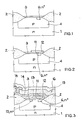
- a gate oxide 3 and a first photoresist layer are applied to an n-doped semiconductor substrate 1 after the production of the active regions and a p-well 4.
- An opening of the photoresist creates an n + -doped region 6 for producing the drain zone by means of ion implantation in the semiconductor substrate 1.
- a second photoresist step with subsequent etching of the gate oxide 3 defines the tunnel window over the n+-doped region 6 according to FIG. 2.
- This is followed by the production of the tunnel oxide layer 11 with a thickness of approximately 100 ⁇ and the deposition of the first polysilicon level, which is processed with a further photolithography and etching step in order to produce the floating gate electrode 12.
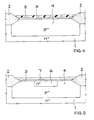
- the further process sequence begins with the production of the interpoly insulation layer 13 and is continued with the creation of the n + -doped source zone 15 by means of ion implantation.
- a second polysilicon level is then applied to produce the gate electrode 14 and then the entire surface is covered with an insulation layer 16. Finally, in a last photolithography and etching step, the contact hole regions 17 are produced and the aluminum interconnects 18 are deposited. Finally, the entire surface is covered with a passivation layer 19.
- the invention is therefore based on the object of creating a memory cell of the type mentioned at the outset, which has a tunnel window whose size is less than 2 ⁇ m ⁇ 2 ⁇ m. It is a further object of the present invention to provide a method for producing such memory cells.
- This object is achieved in that a trench adjoining the side of the drain zone facing away from the channel zone and covered with a dielectric layer is provided, and in that the floating gate electrode extends into the trench in such a way that the tunnel current runs horizontally to the semiconductor surface between Drain zone and floating gate electrode can flow.
- An advantage of this structure according to the invention is the reduction in the size of the tunnel window, which improves the coupling factor, since the area of the tunnel window and the channel area have a major influence on this factor.
- the size of the tunnel window is only determined by the end depth of the trench and the size of the floating gate electrode on the side wall of the trench.
- a corresponding design allows two or more such memory cells according to the invention to be arranged in a trench which, according to a preferred embodiment of the invention, radially surround the trench.
- the trench is cuboid and the floating gate electrode of the memory cell occupies one side wall of the trench.
- a trench with a depth of approximately 1.5 ⁇ m has proven to be particularly advantageous.
- the floating gate electrodes of two memory cells arranged on a cuboid trench are designed such that they occupy two opposite side walls of the trench.
- the method of the invention for producing the memory cell comprises the characterizing features of claim 7.
- Advantageous developments of the method according to the invention can be found in claims 8 to 22.
- the tunnel window is produced in a self-adjusting manner, the adjustment accuracy being less critical than in the production of a conventional memory cell.
- Such a memory cell produced in accordance with the invention advantageously has a small cell size, which leads to a higher integration density, for example in memory modules.
- FIGS. 4 to 10 in the sectional diagram of successive method steps up to a finished memory cell
- FIG. 11 the layout of two EEPROM memory cells according to FIG. 10.
- the size and thickness information in the following description of the process steps up to the finished memory cell relate to a 3 ⁇ m technology.
- FIG. 4 shows a single-crystal, n ⁇ -doped silicon semiconductor substrate 1 after the active surface has been produced by means of local oxidation, the p ⁇ -well (4) and the gate oxide layer (3) with a thickness of approximately 40 nm.
- the definition the active area is produced by producing the field oxide regions 2 from silicon dioxide using a nitride process, while the p ⁇ -well (4) is produced by ion implantation after masking with a first photoresist layer, which is not shown in the figure.
- this figure shows a second photoresist layer 5 which is applied to the gate oxide layer 3 after the removal of the first photoresist layer. After structuring this second photoresist layer 5 and opening the photoresist with another
- Ion implantation produces an n+ region (depletion region) 6 with a width of approx. 5 ⁇ m, a length of approx. 20 ⁇ m and a depth of approx. 1 ⁇ m.
- This second photoresist layer 5 is then removed and a silicon nitride layer 7 is deposited in the region of the p ⁇ -well 4, as can be seen from the arrangement according to FIG.
- the depletion area 6 is then structured using a photoresist technique (not shown in FIG. 5) to produce the trench 8 according to FIG. 6, as a result of which this area 6 breaks down into two identical areas 6a and 6b.
- FIG. 6 shows the arrangement after the trench 8 has been etched, it being evident that the trench 8 extends deeper than the depletion region 6.
- the trench 8 has a width of approximately 5 ⁇ m and a depth of approximately 1.5 ⁇ m, the depletion region 6 being approximately 1 ⁇ m deep.
- the trench 8 divides the previously created depletion region 6 symmetrically into two regions 6a and 6b which are isolated from one another and each represent the drain zones of the later memory cells.
- the trench 8 is completely filled with oxide 9, as a result of which this trench 8 is enlarged both horizontally and vertically, as shown in FIG. 7 by the dashed outline of the trench 8 is.
- a wet etching step follows, with which part of the side walls 10a and 10b of the trench 8 adjacent to the drain zones 6a and 6b - the later tunnel windows 10a and 10b - are exposed, as shown in FIG. Furthermore, according to this FIG. 8, after the silicon nitride layer 7 has been removed, the tunnel oxidation to produce the tunnel oxide 11 is carried out with a thickness of approximately 10 nm.
- the first polysilicon layer which has a thickness of approximately 0.5 ⁇ m and forms the floating gate 12a or 12b, is deposited, the structuring of this layer taking place in such a way that two cells in the trench trench 8 be made at the same time.
- the entire surface in the area of the p ⁇ -well 4 is provided with a polyoxide layer (SiO2), the intermediate insulation layer 13, with a thickness of approximately 60 nm.
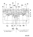
- FIG. 9 shows this arrangement after structuring the second polysilicon layer to form the control gates 14a and 14b, which likewise have a thickness of approximately 0.5 ⁇ m.
- Figure 10 now shows the finished, consisting of two EEPROM memory cells after the generation of the insulation layer 16 as a polyoxide layer (SiO2) with a thickness of about 0.7 microns, the contact hole areas 17, the metal interconnect level 18 and the final surface passivation 19th These last processes are carried out in a known manner.
- SiO2 polyoxide layer
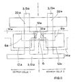
- FIG. 11 shows the layout of the two EEPROM memory cells according to FIG. 10 with a common trench 8, which covers an area of approximately 5 ⁇ m ⁇ 5 ⁇ m.
- Each memory cell has a normal NMOS transistor (select transistor) 20a or 20b connected in series with the FLOTOX transistor, which serves to select the memory cells.
- the area-saving arrangement of the side tunnel windows 10a and 10b can be clearly seen in this figure.
- the two FLOTOX transistors each take up an area of approx. 110 ⁇ m2, while the two memory cells with the select transistors each occupy an area of approximately 500 ⁇ m2, which means a reduction compared to the prior art of approximately 50%.
Landscapes
- Non-Volatile Memory (AREA)
- Semiconductor Memories (AREA)
Abstract
Description
- Die Erfindung betrifft eine nichtflüchtige Speicherzelle bildender FET mit einer Source- und Drainzone sowie einer Floating-Gate-Elektrode als Speicherelektrode zwischen der und dem Halbleiterkörper ein durchtunnelbares Dielektrikum angeordnet ist sowie die Verwendung einer solchen Speicherzelle. Weiterhin betrifft die Erfindung ein Verfahren zur Herstellung einer derartigen Speicherzelle.
- Eine solche nichtflüchtige Speicherzelle ist aus der Literaturstelle "Nichtflüchtige Speicher: EEPROM's und NVRAM's" elektronik industrie 5 (1983), Seiten 13 bis 18, insbesondere auf Seite 13, Bild 1, wo ein von Intel für EEPROM's (electrical erasable programmable read only memory) entwickelter FLOTOX-Speichertransistor (Floating-Gate-Tunnel-Oxid) dargestellt und beschrieben ist.
- Eine solche FLOTOX-Zelle ist elektrisch löschbar und stellt eine Weiterentwicklung der UV-löschbaren dar. Während dort beim Programmieren die Avalanche-Injektion dominiert und das Löschen, also das Entladen des Gates, durch Anregen der Elektronen mit UV-Strahlung erfolgt, nutzt man bei den EEPROM-Zellen zum Programmieren und zum Löschen den Tunnelmechanismus der Elektronen nach Fowler-Nordheim in vertikaler Richtung aus.
- Beim FLOTOX-Speichertransistor von Intel gemäß der oben genannten Literaturstelle liegt das Tunneloxid über der Drainzone. Je nach den anliegenden Potentialen an den Elektroden entsteht im Tunneloxid ein elektrisches Feld, das entweder den Übertritt von Elektronen aus der Drainzone auf das Floating-Gate auslöst - das den Zustand der "logischen 1" repräsentiert - oder aber das das Floating-Gate entlädt, indem die Elektronen wieder zurück zur Drainzone tunneln, womit die "logische O" programmiert ist. Zu jeder Speicherzelle gehört ein zum FLOTOX-Transistor in Serie liegender NMOS-Transistor zur Auswahl der Speicherzellen.
- Im folgenden soll die Herstellung einer solchen bekannten FLOTOX-Speicherzelle anhand der Figuren 1 bis 3 beschrieben werden.
- Gemäß Figur 1 wird auf einem n-dotierten Halbleitersubstrat 1 nach der Herstellung der aktiven Gebiete und einer p-Wanne 4 ein Gate-Oxid 3 und eine erste Fotolackschicht aufgebracht. Durch eine Öffnung des Fotolacks wird zur Herstellung der Drainzone mittels Ionenimplantation im Halbleitersubstrat 1 ein n⁺-dotierter Bereich 6 geschaffen.
- Ein zweiter Fotolackschritt mit anschließendem Ätzen des Gate-Oxids 3 definiert über dem n⁺-dotierten Bereich 6 gemäß Figur 2 das Tunnelfenster. Es folgen die Herstellung der Tunneloxidschicht 11 mit einer Dicke von ca. 100 Å und die Abscheidung der ersten Polysilizium-Ebene, die mit einem weiteren Fotolithografie- und Ätzschritt zur Herstellung der Floating-Gate-Elektrode 12 bearbeitet wird. Der weitere Prozeßablauf beginnt gemäß der Figur 3 mit der Herstellung der Interpoly-Isolationsschicht 13 und wird mit der Schaffung der n⁺-dotierten Sourcezone 15 mittels Ionenimplantation fortgeführt.
- Danach wird zur Herstellung der Gate-Elektrode 14 eine zweite Polysilizium-Ebene aufgetragen und anschließend die Oberfläche ganzflächig mit einer Isolationsschicht 16 abgedeckt. Schließlich werden in einem letzten Fotolithografie- und Ätzschritt die Kontaktlochbereiche 17 erzeugt und die Aluminiumleitbahnen 18 aufgedampft. Abschließend wird die gesamte Oberfläche mit einer Passivierungsschicht 19 abgedeckt.
- Nachteile dieser konventionellen Technik liegen in der Definition des Tunnelfensters durch Fotolithografie-Schritte. Das Design der Speicherzellen muß so ausgelegt sein, daß das Tunnelfenster über dem n⁺-Gebiet 6 liegt und seine Kanten nicht an die Kanten des Aktiv-Gebietes heranreichen. Dies stellt hohe Anforderungen an die Justiergenauigkeit und begrenzt gleichzeitig durch Maskenvorhalte die Minimierung des Designs. Zudem kann die Größe des Tunnelfensters mit vertretbarem Aufwand nur auf 2 µm x 2 µm reduziert werden.
- Der Erfindung liegt daher die Aufgabe zugrunde, eine Speicherzelle der eingangs erwähnten Art zu schaffen, die ein Tunnelfenster aufweist, dessen Größe kleiner als 2 µm x 2 µm ist. Es ist eine weitere Aufgabe der vorliegenden Erfindung, ein Verfahren für die Herstellung solcher Speicherzellen anzugeben.
- Diese Aufgabe wird dadurch gelöst, daß im Halbleiterkörper ein an die der Kanalzone abgewandten Seite der Drainzone angrenzenden und mit einer Dielektrikumsschicht belegter Graben vorgesehen ist, und daß sich die Floating-Gate-Elektrode derart in den Graben erstreckt, daß der Tunnelstrom horizontal zur Halbleiteroberfläche zwischen Drainzone und Floating-Gate-Elektrode fließen kann.
- Ein Vorteil dieser erfindungsgemäßen Struktur besteht in der Verkleinerung des Tunnelfensters, wodurch sich der Ankoppelfaktor verbessert, da die Fläche des Tunnelfensters und des Kanalgebietes einen großen Einfluß auf diesen Faktor haben. Die Größe des Tunnelfensters wird nur noch durch die Endtiefe des Grabens und der Größe der Floating-Gate-Elektrode auf der Seitenwand des Grabens bestimmt. Ferner erlaubt ein entsprechendes Design in einem Graben zwei oder mehrere solcher erfindungsgemäßer Speicherzellen anzuordnen, die gemäß einer bevorzugten Ausführungsform der Erfindung den Graben radial umgeben.
Gemäß einer ersten vorteilhaften Ausbildung der Erfindung ist der Graben quaderförmig ausgebildet und die Floating-Gate-Elektrode der Speicherzelle belegt eine Seitenwand des Grabens. Als besonders vorteilhaft hat sich ein Graben mit einer Tiefe von ca. 1,5 µm erwiesen. - In einer weiteren bevorzugten Weiterbildung der Erfindung werden die Floating-Gate-Elektroden zweier an einem quaderförmigen Graben angeordneten Speicherzellen so ausgebildet, daß sie zwei gegenüberliegende Seitenwände des Grabens belegen.
- Das Verfahren der Erfindung zur Herstellung der Speicherzelle umfaßt die kennzeichnenden Merkmale des Anspruches 7. Vorteilhafte Weiterbildungen des erfindungsgemäßen Verfahrens sind den Ansprüchen 8 bis 22 zu entnehmen. Bei diesem Verfahren erfolgt die Herstellung des Tunnelfensters selbstjustierend, wobei die Justiergenauigkeit weniger kritisch als bei der Herstellung einer herkömmlichen Speicherzelle ist.
- In vorteilhafter Weise weist eine solche erfindungsgemäß hergestellte Speicherzelle eine geringe Zellgröße auf, die zu einer höheren Integrationsdichte, beispielsweise in Speicherbausteinen, führt.
- Die Erfindung soll im folgenden anhand der Zeichnungen näher erläutert werden.
- Es zeigen:
- Die Figuren 4 bis 10 im Schnittbild aufeinanderfolgende Verfahrensschritte bis zu einer fertigen Speicherzelle, die Figur 11 das Layout zweier EEPROM-Speicherzellen gemäß Figur 10.
- In den Figuren sind jeweils gleiche Elemente mit gleichen Bezugszeichen versehen.
- Die Größen- und Dickenangaben in der nachfolgenden Beschreibung der Verfahrensschritte bis zur fertigen Speicherzelle beziehen sich auf eine 3-µm-Technologie.
- Die Figur 4 zeigt ein einkristallines, n⁻-dotiertes Siliziumhalbleitersubstrat 1 nach erfolgter Herstellung der aktiven Fläche mittels lokaler Oxidation, der p⁻-Wanne (4) sowie der Gate-Oxidschicht (3) mit einer Dicke von ca. 40 nm. Die Definition der aktiven Fläche erfolgt durch Erzeugen der Feldoxid-Bereiche 2 aus Siliziumdioxid mittels eines Nitrid-Prozesses, während die Herstellung der p⁻-Wanne (4) durch Ionenimplantation nach erfolgter Maskierung mit einer ersten Fotolackschicht durchgeführt wird, die in der Figur nicht dargestellt ist. Weiterhin zeigt diese Figur eine zweite Fotolackschicht 5, die nach dem Entfernen der ersten Fotolackschicht auf die Gate-Oxidschicht 3 aufgebracht wird. Nach der Strukturierung dieser zweiten Fotolackschicht 5 und dem Öffnen des Fotolacks wird mit einer weiteren
- Ionenimplantation ein n⁺-Gebiet (Depletion-Gebiet) 6 mit einer Breite von ca. 5 µm, einer Länge von ca. 20 µm und einer Tiefe von ca. 1 µm erzeugt. Anschließend wird diese zweite Fotolackschicht 5 entfernt und eine Silizium-Nitridschicht 7 im Bereich der p⁻-Wanne 4 abgeschieden, wie sich aus der Anordnung nach Figur 5 ergibt.
- Anschließend erfolgt mittels einer Fotolacktechnik (in der Figur 5 nicht dargestellt) die Strukturierung des Depletion-Gebietes 6 zur Herstellung des Grabens 8 gemäß Figur 6, wodurch dieses Gebiet 6 in zwei gleiche Bereiche 6a und 6b zerfällt.
- Die Figur 6 zeigt die Anordnung nach der Ätzung des Grabens 8, wobei ersichtlich ist, daß der Graben 8 tiefer als das Depletion-Gebiet 6 reicht. Der Graben 8 weist eine Breite von ca. 5 µm und eine Tiefe von ca. 1,5 µm auf, wobei das Depletion-Gebiet 6 ca. 1 µm tief ist. Außerdem teilt der Graben 8 das vorher hergestellte Depletion-Gebiet 6 symmetrisch in zwei voneinander isolierte Gebiete 6a und 6b, die jeweils die Drainzonen der späteren Speicherzellen darstellen.
- Nun wird mittels thermischer Oxidation unter Verwendung der Silizium-Nitridschicht 7 als Maskierung der Graben 8 komplett mit Oxid 9 aufgefüllt, wodurch sich dieser Graben 8 in horizontaler als auch in vertikaler Richtung vergrößert, wie in Figur 7 durch die gestrichelt gezeichnete Umrandung des Grabens 8 dargestellt ist.
- Es folgt ein Naßätzschritt, mit dem ein Teil der an die Drainzonen 6a und 6b angrenzenden Seitenwände 10a und 10b des Grabens 8 - die späteren Tunnelfenster 10a und 10b - freigelegt werden, wie es die Figur 8 zeigt. Weiterhin wird gemäß dieser Figur 8 nach dem Entfernen der Silizium-Nitridschicht 7 die Tunneloxidation zur Erzeugung des Tunneloxids 11 mit einer Dicke von ca. 10 nm durchgeführt.
- Im weiteren Prozeßablauf erfolgt die Abscheidung der ersten eine Dicke von ca. 0,5 µm aufweisende Polysilizium-Schicht, die das Floating-Gate 12a bzw. 12b bildet, wobei die Strukturierung dieser Schicht so erfolgt, daß in dem Trench-Graben 8 zwei Zellen gleichzeitig hergestellt werden. Nun wird in einem Oxidationsprozeß die gesamte Oberfläche im Bereich der p⁻-Wanne 4 mit einer Polyoxidschicht (SiO₂), der Zwischenisolationsschicht 13, mit einer Dicke von ca. 60 nm versehen.
- Zur Bildung der Sourcezonen 15a und 15b wird eine weitere Ionenimplantation durchgeführt, der die Abscheidung der zweiten Polysilizium-Schicht folgt. Die Figur 9 zeigt diese Anordnung nach der Strukturierung der zweiten Polysilizium-Schicht zur Bildung der Control-Gates 14a und 14b, die ebenfalls eine Dicke von ca. 0,5 µm aufweisen.
- Figur 10 zeigt nun die fertige, aus zwei EEPROM-Speicherzellen bestehende Anordnung nach der Erzeugung der Isolationsschicht 16 als Polyoxidschicht (SiO₂) mit einer Dicke von ca. 0,7 µm, der Kontaktlochbereiche 17, der Metall-Leitbahnebene 18 und der abschließenden Oberflächenpassivierung 19. Diese letzten Prozesse werden in bekannter Weise durchgeführt.
- In Figur 11 ist das Layout der beiden EEPROM-Speicherzellen nach Figur 10 mit einem gemeinsamen Graben 8, der eine Fläche von ca. 5 µm x 5 µm umfaßt, dargestellt. Hierbei gehört zu jeder Speicherzelle ein zum FLOTOX-Transistor in Serie geschalteter normaler NMOS-Transistor (Select-Transistor) 20a bzw. 20b, der zur Auswahl der Speicherzellen dient. Deutlich ist in dieser Figur die flächensparende Anordnung der seitlichen Tunnelfenster 10a und 10b zu erkennen. Die beiden FLOTOX-Transistoren beanspruchen je eine Fläche von ca. 110 µm², während die beiden Speicherzellen mit den Select-Transistoren jeweils eine Fläche von ca. 500 µm² einnehmen, was eine Verkleinerung gegenüber dem Stand der Technik von ca. 50 % bedeutet.
- In einem Trench-Graben können nicht nur zwei Speicherzellen angeordnet werden, sondern bei entsprechender Strukturierung der ersten Polysilizium-Ebene können auch drei und mehrere Zellen gleichzeitig mit einem gemeinsamen Trench-Graben hergestellt werden.
Claims (22)
- Auffüllen des Grabens (8) mit einer Oxidschicht (9) unter Verwendung der Isolationsschicht (7) als Maskierung,
- teilweises Freilegen der Seitenwände (10a, 10b) des Grabens (8) durch Entfernen der Oxidschicht (9),
- Entfernen der Isolationsschicht (7).
Applications Claiming Priority (2)
| Application Number | Priority Date | Filing Date | Title |
|---|---|---|---|
| DE3816358 | 1988-05-13 | ||
| DE3816358A DE3816358A1 (de) | 1988-05-13 | 1988-05-13 | Nichtfluechtige speicherzelle und verfahren zur herstellung |
Publications (3)
| Publication Number | Publication Date |
|---|---|
| EP0341647A2 true EP0341647A2 (de) | 1989-11-15 |
| EP0341647A3 EP0341647A3 (en) | 1990-08-16 |
| EP0341647B1 EP0341647B1 (de) | 1992-12-16 |
Family
ID=6354310
Family Applications (1)
| Application Number | Title | Priority Date | Filing Date |
|---|---|---|---|
| EP89108282A Expired - Lifetime EP0341647B1 (de) | 1988-05-13 | 1989-05-09 | Nichtflüchtige Speicherzelle und Verfahren zur Herstellung |
Country Status (5)
| Country | Link |
|---|---|
| US (1) | US4990979A (de) |
| EP (1) | EP0341647B1 (de) |
| JP (1) | JPH0218969A (de) |
| KR (1) | KR890017809A (de) |
| DE (2) | DE3816358A1 (de) |
Families Citing this family (73)
| Publication number | Priority date | Publication date | Assignee | Title |
|---|---|---|---|---|
| JPH088314B2 (ja) * | 1989-10-11 | 1996-01-29 | 株式会社東芝 | 不揮発性半導体記憶装置およびその製造方法 |
| US5173436A (en) * | 1989-11-21 | 1992-12-22 | Texas Instruments Incorporated | Method of manufacturing an EEPROM with trench-isolated bitlines |
| TW199237B (de) * | 1990-07-03 | 1993-02-01 | Siemens Ag | |
| US5343063A (en) * | 1990-12-18 | 1994-08-30 | Sundisk Corporation | Dense vertical programmable read only memory cell structure and processes for making them |
| US5512505A (en) * | 1990-12-18 | 1996-04-30 | Sandisk Corporation | Method of making dense vertical programmable read only memory cell structure |
| JPH05211338A (ja) * | 1991-10-09 | 1993-08-20 | Mitsubishi Electric Corp | 不揮発性半導体装置 |
| US5712180A (en) * | 1992-01-14 | 1998-01-27 | Sundisk Corporation | EEPROM with split gate source side injection |
| US5313421A (en) * | 1992-01-14 | 1994-05-17 | Sundisk Corporation | EEPROM with split gate source side injection |
| US7071060B1 (en) | 1996-02-28 | 2006-07-04 | Sandisk Corporation | EEPROM with split gate source side infection with sidewall spacers |
| US6222762B1 (en) | 1992-01-14 | 2001-04-24 | Sandisk Corporation | Multi-state memory |
| US5467305A (en) * | 1992-03-12 | 1995-11-14 | International Business Machines Corporation | Three-dimensional direct-write EEPROM arrays and fabrication methods |
| US5399516A (en) * | 1992-03-12 | 1995-03-21 | International Business Machines Corporation | Method of making shadow RAM cell having a shallow trench EEPROM |
| US5196722A (en) * | 1992-03-12 | 1993-03-23 | International Business Machines Corporation | Shadow ram cell having a shallow trench eeprom |
| US5315142A (en) * | 1992-03-23 | 1994-05-24 | International Business Machines Corporation | High performance trench EEPROM cell |
| JP3159850B2 (ja) * | 1993-11-08 | 2001-04-23 | シャープ株式会社 | 不揮発性半導体記憶装置及びその製造方法 |
| JPH08274198A (ja) * | 1995-03-29 | 1996-10-18 | Lg Semicon Co Ltd | Eepromセル及びその製造方法 |
| US5953602A (en) * | 1995-05-26 | 1999-09-14 | Lg Semicon Co., Ltd. | EEPROM cell and related method of making thereof |
| US5606521A (en) * | 1995-06-28 | 1997-02-25 | Philips Electronics North America Corp. | Electrically erasable and programmable read only memory with non-uniform dielectric thickness |
| US5753951A (en) * | 1995-07-25 | 1998-05-19 | International Business Machines Corporation | EEPROM cell with channel hot electron programming and method for forming the same |
| DE19534778C1 (de) * | 1995-09-19 | 1997-04-03 | Siemens Ag | Verfahren zum Erzeugen der Sourcebereiche eines Flash-EEPROM-Speicherzellenfeldes |
| US5777361A (en) * | 1996-06-03 | 1998-07-07 | Motorola, Inc. | Single gate nonvolatile memory cell and method for accessing the same |
| DE19720193C2 (de) * | 1997-05-14 | 2002-10-17 | Infineon Technologies Ag | Integrierte Schaltungsanordnung mit mindestens zwei vertikalen MOS-Transistoren und Verfahren zu deren Herstellung |
| EP1016129B2 (de) | 1997-06-24 | 2009-06-10 | Massachusetts Institute Of Technology | Kontrolle der verspannungsdichte durch verwendung von gradientenschichten und durch planarisierung |
| US6566707B1 (en) * | 1998-01-08 | 2003-05-20 | Sanyo Electric Co., Ltd. | Transistor, semiconductor memory and method of fabricating the same |
| US6225659B1 (en) * | 1998-03-30 | 2001-05-01 | Advanced Micro Devices, Inc. | Trenched gate semiconductor device and method for low power applications |
| US6147377A (en) * | 1998-03-30 | 2000-11-14 | Advanced Micro Devices, Inc. | Fully recessed semiconductor device |
| US6147378A (en) | 1998-03-30 | 2000-11-14 | Advanced Micro Devices, Inc. | Fully recessed semiconductor device and method for low power applications with single wrap around buried drain region |
| US6097061A (en) | 1998-03-30 | 2000-08-01 | Advanced Micro Devices, Inc. | Trenched gate metal oxide semiconductor device and method |
| US7227176B2 (en) | 1998-04-10 | 2007-06-05 | Massachusetts Institute Of Technology | Etch stop layer system |
| US6147379A (en) * | 1998-04-13 | 2000-11-14 | Matsushita Electric Industrial Co., Ltd. | Semiconductor device and method for fabricating the same |
| US6602613B1 (en) | 2000-01-20 | 2003-08-05 | Amberwave Systems Corporation | Heterointegration of materials using deposition and bonding |
| EP1249036A1 (de) * | 2000-01-20 | 2002-10-16 | Amberwave Systems Corporation | Entspannte fehlangepasste epitaxialschichten mit niedriger verspannungsdichte ohne hochtemperatur-wachstum |
| US6593191B2 (en) * | 2000-05-26 | 2003-07-15 | Amberwave Systems Corporation | Buried channel strained silicon FET using a supply layer created through ion implantation |
| JP3573691B2 (ja) * | 2000-07-03 | 2004-10-06 | シャープ株式会社 | 不揮発性半導体記憶装置およびその製造方法 |
| AU2001283138A1 (en) * | 2000-08-07 | 2002-02-18 | Amberwave Systems Corporation | Gate technology for strained surface channel and strained buried channel mosfet devices |
| JP2004507084A (ja) * | 2000-08-16 | 2004-03-04 | マサチューセッツ インスティテュート オブ テクノロジー | グレーデッドエピタキシャル成長を用いた半導体品の製造プロセス |
| US6649480B2 (en) * | 2000-12-04 | 2003-11-18 | Amberwave Systems Corporation | Method of fabricating CMOS inverter and integrated circuits utilizing strained silicon surface channel MOSFETs |
| US20020100942A1 (en) * | 2000-12-04 | 2002-08-01 | Fitzgerald Eugene A. | CMOS inverter and integrated circuits utilizing strained silicon surface channel MOSFETs |
| US6723661B2 (en) * | 2001-03-02 | 2004-04-20 | Amberwave Systems Corporation | Relaxed silicon germanium platform for high speed CMOS electronics and high speed analog circuits |
| US6703688B1 (en) * | 2001-03-02 | 2004-03-09 | Amberwave Systems Corporation | Relaxed silicon germanium platform for high speed CMOS electronics and high speed analog circuits |
| US6830976B2 (en) * | 2001-03-02 | 2004-12-14 | Amberwave Systems Corproation | Relaxed silicon germanium platform for high speed CMOS electronics and high speed analog circuits |
| US6724008B2 (en) | 2001-03-02 | 2004-04-20 | Amberwave Systems Corporation | Relaxed silicon germanium platform for high speed CMOS electronics and high speed analog circuits |
| US6940089B2 (en) * | 2001-04-04 | 2005-09-06 | Massachusetts Institute Of Technology | Semiconductor device structure |
| US6936887B2 (en) * | 2001-05-18 | 2005-08-30 | Sandisk Corporation | Non-volatile memory cells utilizing substrate trenches |
| US6894343B2 (en) * | 2001-05-18 | 2005-05-17 | Sandisk Corporation | Floating gate memory cells utilizing substrate trenches to scale down their size |
| WO2002103760A2 (en) * | 2001-06-14 | 2002-12-27 | Amberware Systems Corporation | Method of selective removal of sige alloys |
| US7301180B2 (en) * | 2001-06-18 | 2007-11-27 | Massachusetts Institute Of Technology | Structure and method for a high-speed semiconductor device having a Ge channel layer |
| WO2003001671A2 (en) * | 2001-06-21 | 2003-01-03 | Amberwave Systems Corporation | Improved enhancement of p-type metal-oxide-semiconductor field-effect transistors |
| WO2003015142A2 (en) * | 2001-08-06 | 2003-02-20 | Massachusetts Institute Of Technology | Formation of planar strained layers |
| US7138649B2 (en) * | 2001-08-09 | 2006-11-21 | Amberwave Systems Corporation | Dual-channel CMOS transistors with differentially strained channels |
| US6974735B2 (en) * | 2001-08-09 | 2005-12-13 | Amberwave Systems Corporation | Dual layer Semiconductor Devices |
| WO2003025984A2 (en) | 2001-09-21 | 2003-03-27 | Amberwave Systems Corporation | Semiconductor structures employing strained material layers with defined impurity gradients and methods for fabricating same |
| AU2002341803A1 (en) * | 2001-09-24 | 2003-04-07 | Amberwave Systems Corporation | Rf circuits including transistors having strained material layers |
| US6801761B2 (en) * | 2002-02-15 | 2004-10-05 | Broadcom Corp. | Programmable mixer and radio applications thereof |
| WO2003079415A2 (en) | 2002-03-14 | 2003-09-25 | Amberwave Systems Corporation | Methods for fabricating strained layers on semiconductor substrates |
| US7307273B2 (en) * | 2002-06-07 | 2007-12-11 | Amberwave Systems Corporation | Control of strain in device layers by selective relaxation |
| US20030227057A1 (en) * | 2002-06-07 | 2003-12-11 | Lochtefeld Anthony J. | Strained-semiconductor-on-insulator device structures |
| US7615829B2 (en) * | 2002-06-07 | 2009-11-10 | Amberwave Systems Corporation | Elevated source and drain elements for strained-channel heterojuntion field-effect transistors |
| US7335545B2 (en) * | 2002-06-07 | 2008-02-26 | Amberwave Systems Corporation | Control of strain in device layers by prevention of relaxation |
| US6995430B2 (en) * | 2002-06-07 | 2006-02-07 | Amberwave Systems Corporation | Strained-semiconductor-on-insulator device structures |
| US7074623B2 (en) * | 2002-06-07 | 2006-07-11 | Amberwave Systems Corporation | Methods of forming strained-semiconductor-on-insulator finFET device structures |
| US7138310B2 (en) * | 2002-06-07 | 2006-11-21 | Amberwave Systems Corporation | Semiconductor devices having strained dual channel layers |
| US6946371B2 (en) * | 2002-06-10 | 2005-09-20 | Amberwave Systems Corporation | Methods of fabricating semiconductor structures having epitaxially grown source and drain elements |
| US6982474B2 (en) * | 2002-06-25 | 2006-01-03 | Amberwave Systems Corporation | Reacted conductive gate electrodes |
| EP2267762A3 (de) | 2002-08-23 | 2012-08-22 | Taiwan Semiconductor Manufacturing Co., Ltd. | Halbleiter-Heterostrukturen mit reduzierter Anhäufung von Versetzungen und entsprechende Herstellungsverfahren |
| US7594967B2 (en) * | 2002-08-30 | 2009-09-29 | Amberwave Systems Corporation | Reduction of dislocation pile-up formation during relaxed lattice-mismatched epitaxy |
| EP2337062A3 (de) * | 2003-01-27 | 2016-05-04 | Taiwan Semiconductor Manufacturing Company, Limited | Herstellungsverfahren von HALBLEITERSTRUKTUREN MIT STRUKTURHOMOGENITÄT |
| CN100437970C (zh) * | 2003-03-07 | 2008-11-26 | 琥珀波系统公司 | 一种结构及用于形成半导体结构的方法 |
| KR100567624B1 (ko) * | 2004-06-15 | 2006-04-04 | 삼성전자주식회사 | 반도체 장치의 제조 방법 |
| US7393733B2 (en) * | 2004-12-01 | 2008-07-01 | Amberwave Systems Corporation | Methods of forming hybrid fin field-effect transistor structures |
| US20060113603A1 (en) * | 2004-12-01 | 2006-06-01 | Amberwave Systems Corporation | Hybrid semiconductor-on-insulator structures and related methods |
| KR100661186B1 (ko) * | 2005-03-23 | 2006-12-22 | 주식회사 하이닉스반도체 | 플래쉬 메모리 소자의 제조방법 |
| US7795605B2 (en) * | 2007-06-29 | 2010-09-14 | International Business Machines Corporation | Phase change material based temperature sensor |
Family Cites Families (6)
| Publication number | Priority date | Publication date | Assignee | Title |
|---|---|---|---|---|
| US4435790A (en) * | 1980-12-24 | 1984-03-06 | Fairchild Camera And Instrument Corporation | High speed, nonvolatile, electrically erasable memory cell and system |
| US4471471A (en) * | 1981-12-31 | 1984-09-11 | International Business Machines Corporation | Non-volatile RAM device |
| EP0103043B1 (de) * | 1982-09-15 | 1987-03-18 | Deutsche ITT Industries GmbH | CMOS-Speicherzelle mit potentialmässig schwebendem Speichergate |
| IT1213218B (it) * | 1984-09-25 | 1989-12-14 | Ates Componenti Elettron | Processo per la fabbricazione di una cella di memoria non volatile con area di ossido sottile di dimensioni molto piccole, e cella ottenuta con il processo suddetto. |
| US4713677A (en) * | 1985-02-28 | 1987-12-15 | Texas Instruments Incorporated | Electrically erasable programmable read only memory cell including trench capacitor |
| US4796228A (en) * | 1986-06-02 | 1989-01-03 | Texas Instruments Incorporated | Erasable electrically programmable read only memory cell using trench edge tunnelling |
-
1988
- 1988-05-13 DE DE3816358A patent/DE3816358A1/de active Granted
-
1989
- 1989-04-27 US US07/350,722 patent/US4990979A/en not_active Expired - Fee Related
- 1989-05-09 EP EP89108282A patent/EP0341647B1/de not_active Expired - Lifetime
- 1989-05-09 DE DE8989108282T patent/DE58902995D1/de not_active Expired - Fee Related
- 1989-05-09 KR KR1019890006167A patent/KR890017809A/ko not_active Ceased
- 1989-05-12 JP JP1117611A patent/JPH0218969A/ja active Pending
Also Published As
| Publication number | Publication date |
|---|---|
| EP0341647A3 (en) | 1990-08-16 |
| DE3816358C2 (de) | 1991-07-04 |
| US4990979A (en) | 1991-02-05 |
| DE3816358A1 (de) | 1989-11-23 |
| KR890017809A (ko) | 1989-12-18 |
| EP0341647B1 (de) | 1992-12-16 |
| DE58902995D1 (de) | 1993-01-28 |
| JPH0218969A (ja) | 1990-01-23 |
Similar Documents
| Publication | Publication Date | Title |
|---|---|---|
| EP0341647B1 (de) | Nichtflüchtige Speicherzelle und Verfahren zur Herstellung | |
| DE4016346C2 (de) | Nichtflüchtige Halbleiterspeichervorrichtung und ein Verfahren zu ihrer Herstellung | |
| DE19527682B4 (de) | Verfahren zur Herstellung einer EEPROM-Flashzelle | |
| DE69231356T2 (de) | Nichtflüchtige Speicherzelle und Anordnungsarchitektur | |
| DE4114344C2 (de) | Herstellungsverfahren und Aufbau einer nicht-flüchtigen Halbleiterspeichereinrichtung mit einer Speicherzellenanordnung und einem peripheren Schaltkreis | |
| DE69130163T2 (de) | Verfahren zur Herstellung einer MOS-EEPROM-Transistorzelle mit schwebendem Gate | |
| DE3782279T2 (de) | Elektrisch veraenderbare, nichtfluechtige speicheranordnung vom schwebenden gate-typ, mit geringerer tunneleffektflaeche und herstellung derselben. | |
| DE19612948B4 (de) | Verfahren zur Herstellung einer Halbleitereinrichtung mit vertiefter Kanalstruktur | |
| DE69333359T2 (de) | Herstellungsverfahren einer EEPROM-Zellen-Matrix | |
| DE69918636T2 (de) | Verfahren zur herstellung einer halbleitervorrichtung | |
| DE10353387B4 (de) | Verfahren zur Herstellung einer Leistungstransistoranordnung und Leistungstransistoranordnung | |
| DE69427532T2 (de) | Verfahren zur reduzierung den abstandes zwischen den horizontalen benachbarten schwebenden gates einer flash eprom anordnung | |
| DE69319384T2 (de) | Mit allen Funktionen ausgestattete hochintegrierte EEPROM-Zelle mit Poly-Tunnel-Zwischenstück und Herstellungsverfahren | |
| DE69312676T2 (de) | Prozess zur Herstellung von integrierten Bauelementen einschliesslich nichtvolatiler Speicher und Transistoren mit Tunneloxidschutz | |
| DE102004043517B4 (de) | Halbleiterspeicherbauelement mit Speicherzellen mit Floating-Gate-Elektrode und Herstellungsverfahren | |
| DE69429973T2 (de) | Verfahren zur Herstellung von Flash EPROM Anordungen | |
| DE69027576T2 (de) | Eeprom mit grabenisolierten Bitleitungen | |
| DE3540422C2 (de) | Verfahren zum Herstellen integrierter Strukturen mit nicht-flüchtigen Speicherzellen, die selbst-ausgerichtete Siliciumschichten und dazugehörige Transistoren aufweisen | |
| DE10206057B4 (de) | Nichtflüchtiges Speicherbauelement und Verfahren zu seiner Herstellung | |
| DE69732618T2 (de) | Eine asymmetrische Zelle für eine Halbleiterspeichermatrix und deren Herstellungsmethode | |
| DE10324550B4 (de) | Herstellungsverfahren für eine NROM-Halbleiterspeichervorrichtung | |
| DE69326749T2 (de) | Nichtflüchtiger Speicher mit Schutzdiode | |
| DE69316858T2 (de) | Nichtflüchtige Halbleiteranordnung und Verfahren zur ihrer Herstellung | |
| DE69121775T2 (de) | Auslöschbare programmierbare Speicheranordnung | |
| DE69528962T2 (de) | Verbesserte isolierung zwischen diffusions-leitungen in einem speicherfeld |
Legal Events
| Date | Code | Title | Description |
|---|---|---|---|
| PUAI | Public reference made under article 153(3) epc to a published international application that has entered the european phase |
Free format text: ORIGINAL CODE: 0009012 |
|
| AK | Designated contracting states |
Kind code of ref document: A2 Designated state(s): DE FR GB IT NL |
|
| PUAL | Search report despatched |
Free format text: ORIGINAL CODE: 0009013 |
|
| AK | Designated contracting states |
Kind code of ref document: A3 Designated state(s): DE FR GB IT NL |
|
| 17P | Request for examination filed |
Effective date: 19900903 |
|
| 17Q | First examination report despatched |
Effective date: 19920521 |
|
| GRAA | (expected) grant |
Free format text: ORIGINAL CODE: 0009210 |
|
| AK | Designated contracting states |
Kind code of ref document: B1 Designated state(s): DE FR GB IT NL |
|
| GBT | Gb: translation of ep patent filed (gb section 77(6)(a)/1977) |
Effective date: 19921215 |
|
| ITF | It: translation for a ep patent filed | ||
| REF | Corresponds to: |
Ref document number: 58902995 Country of ref document: DE Date of ref document: 19930128 |
|
| ET | Fr: translation filed | ||
| PGFP | Annual fee paid to national office [announced via postgrant information from national office to epo] |
Ref country code: GB Payment date: 19930422 Year of fee payment: 5 |
|
| PGFP | Annual fee paid to national office [announced via postgrant information from national office to epo] |
Ref country code: FR Payment date: 19930511 Year of fee payment: 5 |
|
| PGFP | Annual fee paid to national office [announced via postgrant information from national office to epo] |
Ref country code: NL Payment date: 19930531 Year of fee payment: 5 |
|
| PGFP | Annual fee paid to national office [announced via postgrant information from national office to epo] |
Ref country code: DE Payment date: 19930707 Year of fee payment: 5 |
|
| PLBE | No opposition filed within time limit |
Free format text: ORIGINAL CODE: 0009261 |
|
| STAA | Information on the status of an ep patent application or granted ep patent |
Free format text: STATUS: NO OPPOSITION FILED WITHIN TIME LIMIT |
|
| 26N | No opposition filed | ||
| PG25 | Lapsed in a contracting state [announced via postgrant information from national office to epo] |
Ref country code: GB Effective date: 19940509 |
|
| PG25 | Lapsed in a contracting state [announced via postgrant information from national office to epo] |
Ref country code: NL Effective date: 19941201 |
|
| GBPC | Gb: european patent ceased through non-payment of renewal fee |
Effective date: 19940509 |
|
| NLV4 | Nl: lapsed or anulled due to non-payment of the annual fee | ||
| PG25 | Lapsed in a contracting state [announced via postgrant information from national office to epo] |
Ref country code: FR Effective date: 19950131 |
|
| PG25 | Lapsed in a contracting state [announced via postgrant information from national office to epo] |
Ref country code: DE Effective date: 19950201 |
|
| REG | Reference to a national code |
Ref country code: FR Ref legal event code: ST |
|
| PG25 | Lapsed in a contracting state [announced via postgrant information from national office to epo] |
Ref country code: IT Free format text: LAPSE BECAUSE OF NON-PAYMENT OF DUE FEES Effective date: 20050509 |