EP0337052B1 - Vorrichtung zur Bremsung von Spulen - Google Patents
Vorrichtung zur Bremsung von Spulen Download PDFInfo
- Publication number
- EP0337052B1 EP0337052B1 EP89100325A EP89100325A EP0337052B1 EP 0337052 B1 EP0337052 B1 EP 0337052B1 EP 89100325 A EP89100325 A EP 89100325A EP 89100325 A EP89100325 A EP 89100325A EP 0337052 B1 EP0337052 B1 EP 0337052B1
- Authority
- EP
- European Patent Office
- Prior art keywords
- electromagnet
- air gap
- ring
- armature
- armature ring
- Prior art date
- Legal status (The legal status is an assumption and is not a legal conclusion. Google has not performed a legal analysis and makes no representation as to the accuracy of the status listed.)
- Expired - Lifetime
Links
- 230000005540 biological transmission Effects 0.000 claims description 2
- 230000005672 electromagnetic field Effects 0.000 claims description 2
- 238000004904 shortening Methods 0.000 claims description 2
- 230000000694 effects Effects 0.000 claims 1
- 230000005281 excited state Effects 0.000 claims 1
- 238000004804 winding Methods 0.000 abstract description 11
- 239000000463 material Substances 0.000 description 13
- 230000005284 excitation Effects 0.000 description 7
- 238000000034 method Methods 0.000 description 5
- 238000003860 storage Methods 0.000 description 3
- XEEYBQQBJWHFJM-UHFFFAOYSA-N Iron Chemical compound [Fe] XEEYBQQBJWHFJM-UHFFFAOYSA-N 0.000 description 2
- 239000004753 textile Substances 0.000 description 2
- 229910052742 iron Inorganic materials 0.000 description 1
- 238000004519 manufacturing process Methods 0.000 description 1
- 239000002184 metal Substances 0.000 description 1
- 229910052751 metal Inorganic materials 0.000 description 1
- 230000001105 regulatory effect Effects 0.000 description 1
Images
Classifications
-
- D—TEXTILES; PAPER
- D07—ROPES; CABLES OTHER THAN ELECTRIC
- D07B—ROPES OR CABLES IN GENERAL
- D07B7/00—Details of, or auxiliary devices incorporated in, rope- or cable-making machines; Auxiliary apparatus associated with such machines
- D07B7/02—Machine details; Auxiliary devices
- D07B7/06—Bearing supports or brakes for supply bobbins or reels
-
- B—PERFORMING OPERATIONS; TRANSPORTING
- B65—CONVEYING; PACKING; STORING; HANDLING THIN OR FILAMENTARY MATERIAL
- B65H—HANDLING THIN OR FILAMENTARY MATERIAL, e.g. SHEETS, WEBS, CABLES
- B65H59/00—Adjusting or controlling tension in filamentary material, e.g. for preventing snarling; Applications of tension indicators
- B65H59/02—Adjusting or controlling tension in filamentary material, e.g. for preventing snarling; Applications of tension indicators by regulating delivery of material from supply package
- B65H59/04—Adjusting or controlling tension in filamentary material, e.g. for preventing snarling; Applications of tension indicators by regulating delivery of material from supply package by devices acting on package or support
-
- B—PERFORMING OPERATIONS; TRANSPORTING
- B65—CONVEYING; PACKING; STORING; HANDLING THIN OR FILAMENTARY MATERIAL
- B65H—HANDLING THIN OR FILAMENTARY MATERIAL, e.g. SHEETS, WEBS, CABLES
- B65H75/00—Storing webs, tapes, or filamentary material, e.g. on reels
- B65H75/02—Cores, formers, supports, or holders for coiled, wound, or folded material, e.g. reels, spindles, bobbins, cop tubes, cans, mandrels or chucks
- B65H75/18—Constructional details
- B65H75/30—Arrangements to facilitate driving or braking
Definitions
- the present invention relates to a device for braking coils rotatably mounted about their axis, of which strand-like material, such as tapes, wires, threads and the like. Can be unwound and, after a positive connection to a drive shaft, these coils can be rewound with the corresponding strand-like material.
- the force of an electromagnetic field is used for the generation of the braking torque or for the torque transmission, the anchor being a metal ring which can be moved against the spring force and is arranged on the flange side of the coil, via which the magnetic force flow closes when an electromagnet is excited.
- coil brakes in which the braking torque is already generated by an electromagnet, are known from the internal status of Tecknik, means being available which depend on one another change the excitation current that determines the braking torque of the electromagnet from the coil radius or the coil rotation speed or from the coil weight.
- the invention is therefore based on the object of finding a way which meets both requirements.
- This object is achieved in a generic device according to the invention in that an air gap is provided between the armature ring and the electromagnet.
- This air gap which is advantageously 0.1-1.5 mm in width, preferably 0.2-0.8 mm, allows for active operation, i.e. the unwinding process, with a reduced excitation voltage of the electromagnet, a sufficient control range for the braking force without the jerky holding of the armature ring and thus a sudden stop of the unwinding spool.
- the invention guarantees that with a correspondingly increased or full excitation voltage in passive operation, i.e. During the winding process, the required torque is transferred to the spool without slippage.
- the air gap can be formed, for example, by shortening the iron path in the magnetic yoke of the electromagnet.
- Another possibility according to the invention to provide a forced air gap is expediently that the friction or grinding surface of the electromagnet including the ends of the magnet yoke facing the armature ring is covered by an insulating washer corresponding to the width of the air gap. In this way, the braking power required for unwinding is easily provided.
- the described invention is applicable to any area, be it that it involves winding processes in the textile industry, or that the production of electrical cables and lines requires appropriate measures.
- a particularly preferred area of application is, for example, the stranding or roping of stranding elements by means of a known device (DE-OS 3609146) from a drivable stranding body and storage receptacles in the form of coils, in which the stranding body and the coils are combined in one unit and are available in duplicate and in Form of this unit are interchangeable, the unit with just filled coils forms the active part and the other with the coils to be filled forms the passive part.
- a device is suitable in the same way for stranding individual stranding elements as well as for stranding layers onto elongated material.
- the respective units are compact systems, which can be loaded for a short time after the storage stocks are idle.
- the loading itself can be carried out on an order basis, that is, according to a predetermined program, the stock receptacles are filled with stranding elements of different or the same length and / or cross sections and / or material.
- the bobbins depending on the operating mode (active-passive), either run without brake force control or slip-free connected to the drive shaft.
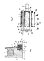
- FIG. 1 illustrates the invention itself on a larger scale than FIG. 2
- FIG. 2 shows an advantageous application of the invention.
- the coil 2 for example filled with a wire supply 1, has a recess 4 on the end face of the coil core 3, in which the armature ring 5 is guided so as to be movable in the axial direction.
- the anchor ring 5 is held by a screw 6 with which the retaining ring 7 is fastened to the base of the recess.
- the non-positive connection between the retaining ring 7 and the anchor ring 5 is achieved by leaf springs 8 mutually screwed to the adjacent parts.
- the armature ring 5 Opposite the armature ring 5 is the electromagnet 9, also arranged in a ring, it consists of the excitation winding 10 and the magnetic yoke 11 and a friction or grinding surface 12.
- the coil 2 On the shaft 13 of a winding or stranding machine, the coil 2 is free by means of ball bearings (not shown) rotatably mounted, so that the armature ring 5, attached to the coil core 3, rotates with.
- the electromagnet 9 is rigidly connected to the shaft 13.
- the armature ring 5 When the excitation winding 10 is loaded with the full excitation voltage, e.g. of 24V, the armature ring 5 is briefly tightened, the previously possibly free-running coil is braked. The resulting frictional connection between the electromagnet 9 rigidly connected to the shaft 13 and the armature ring 5 allows the coil 2 to be filled when the shaft 13 is driven by winding up wires or strips.
- the full excitation voltage e.g. of 24V
- the electromagnet 9 is de-energized to de-energize the armature ring, the material can be pulled off when the spool 2 is freely rotating.
- the air gap 14 brings about a uniform braking of the coil 2 during unwinding of the material, for example with a reduced excitation voltage of 0-6V, without influencing the positive connection required for driving the shaft 13 for the purpose of winding.
- the magnetic yoke 11 is set back by the width of the gap 14; this can be achieved e.g. by turning off, i.e. mechanically removing material from the yoke faces.
- FIG. 2 shows the use of a device according to FIG. 1 in the already mentioned rope-in or rope-in device, in which the stranding body and storage receptacles are combined into one unit and are available in duplicate.
- a stand 16 is used for mounting, the drive takes place via the gear 17, and a possibly free-running hollow shaft 18 is used to hold the coils 2.
- the stranding elements 19, for example individual wires, which are guided in the pipe or on the pipe, are made of Coils 2, as shown, drawn off and fed to the stranding point 21 after deflection by a guide disk 20. If the stranding elements 19 are not to be stranded together, but rather are to be stranded onto a cable core, the cable core itself is guided through the hollow shaft 18 to the stranding point 21.
- two devices 22 and 23 consisting of stranding bodies and coils are arranged side by side in one plane.
- the structure of these units is identical; the two units 22 and 23 can be pivoted relative to one another via a suitable changing device 24.
- This pivoting is expediently revolver-like, this means in the specific case that after emptying the coils 2, the unit 22 is pivoted out of the operating position and at the same time the unit 23 is returned to the operating position.
- the charging station 24 is used to fill the unit 22, which is swiveled out with empty coils, in which, for example, stranding elements, for example wires, of different dimensions are present in a suitable magazine and are filled into the coils 2 according to a program by means of the schematically indicated laying device 25.
- the loading process can also take place automatically, as can the swiveling of the units into the loading and / or operating position.
- the coils 2 present in this cable or cable device are constructed according to FIG. 1 and equipped with the clutch / brake device according to the invention.
- the air gap according to the invention can also be produced by an insulating washer covering the friction surface 12 and having a thickness adapted to the gap width.
Landscapes
- Tension Adjustment In Filamentary Materials (AREA)
- Braking Arrangements (AREA)
- Storage Of Web-Like Or Filamentary Materials (AREA)
- Ropes Or Cables (AREA)
- Tires In General (AREA)
- Unwinding Webs (AREA)
- Agricultural Chemicals And Associated Chemicals (AREA)
- Unwinding Of Filamentary Materials (AREA)
- Discharge Heating (AREA)
- Windings For Motors And Generators (AREA)
- Reciprocating, Oscillating Or Vibrating Motors (AREA)
- Registering, Tensioning, Guiding Webs, And Rollers Therefor (AREA)
Description
- Die vorliegende Erfindung betrifft eine Vorrichtung zur Bremsung von um ihre Achse drehbar gelagerten Spulen, von denen strangförmiges Gut, wie Bänder, Drähte, Fäden und dergl. abwickelbar und nach kraftschlüssiger Verbindung mit einer Antriebswelle diese Spulen mit entsprechendem strangförmigen Gut wieder bewickelbar sind. Hierbei wird die Kraftwirkung eines elektromagnetischen Feldes für die Erzeugung des Bremsmomentes bzw. für die Drehmomentübertragung ausgenutzt, wobei als Anker ein gegen Federkraft bewegbarer, an der Flanschseite der Spule angeordneter metallischer Ring dient, über den sich im erregten Zustand eines Elektromagneten der magnetische Kraftfluß schließt.
- In vielen Fällen, so bei Textilmaschinen, Verseil- oder Aufseilmaschinen usw. ist es erforderlich, die Spulen, von denen strangförmiges Gut, wie Bänder, Drähte oder Fäden, abläuft, so zu bremsen, daß in dem ablaufenden Gut eine konstante oder nahezu konstante Zugspannung vorhanden ist, da anderenfalls das strangförmige Gut zu schlagen oder zu reißen beginnt. Bekannt sind, aus den internen Stand der Tecknik, zu diesem Zweck Spulenbremsen, bei denen das Bremsmoment bereits durch einen Elektromagneten erzeugt wird, wobei Mittel vorhanden sind, die in Abhängigkeit vom Spulenradius oder von der Spulenrotationsgeschwindigkeit bzw. vom Spulengewicht den das Bremsmoment des Elektromagneten bestimmenden Erregerstrom ändern. Nun gibt es aber Fälle, bei denen es nicht nur darauf ankommt, eine Spule beim Abwickeln des strangförmigen Gutes abzubremsen, sondern eine solche Bremse gleichzeitig als Kupplung dann zu benutzen, wenn die Spulen nach dem Leerwickeln wieder mit Bändern oder Drähten aus Vorräten bewickelt werden sollen. Dann reicht die bekannte Vorrichtung nicht aus, einmal das volle Drehmoment zu übertragen (Bewicklung) und zum anderen eine Regelung der Bremskraft (Abwicklung) herbeizuführen, um einen störungsfreien Ablauf des strangförmigen Gutes von der Spule zu gewährleisten.
- Der Erfindung liegt deshalb die Aufgabe zugrunde, eine Möglichkeit zu finden, die beiden Forderungen gerecht wird.
- Gelöst wird diese Aufgabe bei einer gattungsgemäßen Vorrichtung nach der Erfindung dadurch, daß zwischen dem Ankerring und dem Elektromagneten ein Luftspalt vorgesehen ist. Dieser Luftspalt, der in seiner Breite vorteilhaft 0,1-1,5 mm, vorzugsweise 0,2-0,8 mm beträgt, gestattet für den aktiven Betrieb, d.h. den Abwickelvorgang, bei verminderter Erregerspannung des Elektromagneten einen ausreichenden Regelbereich für die Bremskraft, ohne daß es zu einem ruckartigen Festhalten des Ankerringes und damit zu einem plötzlichen Halt der Abwickelspule kommt. Gleichzeitig bietet die Erfindung Gewähr dafür, daß bei entsprechend erhöhter bzw. voller Erregerspannung im passiven Betrieb, d.h. beim Aufwickelvorgang, das benötigte Drehmoment schlupffrei auf die Spule übertragen wird.
- Die nach der Erfindung vorgeschlagene Problemlösung kann auf einfache Weise realisiert werden. Bei Einrichtungen, von denen die Erfindung ausgeht, kann der Luftspalt z.B. durch Verkürzung des Eisenweges im Magnetjoch des Elektromagneten gebildet werden. Hierzu wird man zweckmäßig das dem Ankerring zugekehrte Ende des Magnetjoches um die Breite des Luftspaltes gegenüber der Reib- oder Schleiffläche des Elektromagneten zurücksetzen.
- Eine andere Möglichkeit, gemäß der Erfindung einen Zwangsluftspalt vorzusehen ist zweckmäßig die, daß die Reib- oder Schleiffläche des Elektromagneten einschließlich der dem Ankerring zugekehrten Enden des Magnetjoches von einer der Breite des Luftspaltes entsprechenden Isolierscheibe überdeckt wird. Auf einfachen Wege ist so die beim Abwickeln geforderte Regelmöglichkeit der Bremskraft gegeben.
- Die beschriebene Erfindung ist auf beliebige Bereiche anwendbar, sei es, daß es um Wickelvorgänge in der Textilindustrie geht, sei es, daß die Herstellung elektrischer Kabel und Leitungen entsprechende Maßnahmen erforderlich macht. Ein besonders bevorzugter Anwendungsbereich ist z.B. das Verseilen oder Aufseilen von Verseilelementen mittels einer bekannten Vorrichtung (DE-OS 3609146) aus einem antriebbaren Verseilkörper und Vorratsaufnahmen in Form von Spulen, bei der der Verseilkörper und die Spulen zu einer Einheit zusammengefaßt in doppelter Ausführung vorhanden und in Form dieser Einheit gegeneinander austauschbar sind, wobei die Einheit mit gerade gefüllten Spulen den aktiven Teil und die andere mit den zu füllenden Spulen den passiven Teil bildet. Eine solche Einrichtung ist in gleicher Weise zur Verseilung von einzelnen Verseilelementen als auch zum Aufseilen von Lagen auf langgestrecktes Gut geeignet. Die jeweiligen Einheiten sind kompakte Systeme, die nach Leerlauf der Vorratsaufnahmen kurzfristig beladen werden können. Die Beladung selbst kann auftragsbezogen vorgenommen werden, d.h., nach einem vorgegebenen Programm werden die Vorratsaufnahmen mit Verseilelementen unterschiedlicher oder gleicher Länge und/oder Querschnitte und/oder Material gefüllt. Für den hierbei notwendigen wechselnden Betrieb, der störungsfrei ablaufen und mit hohen Abzugsbzw. Aufspulgeschwindigkeiten durchgeführt werden soll, ist es zwingend erforderlich, daß die Spulen je nach Betriebsart (aktiv-passiv) entweder problemlos bremskraftgeregelt oder schlupffrei mit der Antriebswelle verbunden umlaufen.
- Die Erfindung sei an Hand der in den Fig. 1 und 2 dargestellten Ausführungsbeispiele näher erläutert.
- Die Fig. 1 verdeutlicht in einem gegenüber der Fig. 2 vergrößerten Maßstab die Erfindung selbst, die Fig. 2 zeigt eine vorteilhafte Anwendungsmöglichkeit der Erfindung.
- Die z.B. mit einem Drahtvorrat 1 gefüllte Spule 2 weist an der Stirnseite des Spulenkernes 3 eine Ausnehmung 4 auf, in der der Ankerring 5 in Achsrichtung bewegbar geführt ist. Gehalten wird der Ankerring 5 durch eine Verschraubung 6, mit der der Haltering 7 am Grund der Ausnehmung befestigt ist. Die kraftschlüssige Verbindung zwischen dem Haltering 7 und dem Ankerring 5 wird durch wechselseitig mit den angrenzenden Teilen verschraubte Blattfedern 8 erreicht. Dem Ankerring 5 gegenüber ist der Elektromagnet 9, ebenfalls in Ringform angeordnet, er besteht aus der Erregerwicklung 10 und dem Magnetjoch 11 sowie einer Reib- oder Schleiffläche 12. Auf der Welle 13 einer Wickel- oder Verseilmaschine ist die Spule 2 mittels nicht dargestellter Kugellager frei drehbar gelagert, damit läuft auch der Ankerring 5, am Spulenkern 3 befestigt, mit um. Mit der Welle 13 starr verbunden ist dagegen der Elektromagnet 9.
- Bei Beaufschlagung der Erregerwicklung 10 mit der vollen Erregerspannung, z.B. von 24V, wird der Ankerring 5 kurzfristig angezogen, die vorher möglicherweise noch freilaufende Spule wird abgebremst. Der hierdurch bewirkte Kraftschluß zwischen dem mit der Welle 13 starr verbundenen Elektromagneten 9 und dem Ankerring 5 erlaubt es, bei Antrieb der Welle 13 durch Aufwickeln von Drähten oder Bändern die Spule 2 zu füllen.
- Soll in einem anschließenden Arbeitsschritt das auf die Spule 2 aufgewickelte Gut wieder abgezogen werden, etwa zum Zwecke einer Ver- oder Aufseilung, wird durch Entregung des Elektromagneten 9 der Kraftschluß zum Ankerring unterbrochen, das Gut kann bei freiem Umlauf der Spule 2 abgezogen werden. Um für diesen Fall nun eine ausreichende Regelmöglichkeit der Bremskraft zu erreichen, die benötigt wird, um unabhängig vom Wickeldurchmesser des auf der Spule 2 aufgewickelten Gutes 1, unabhängig von Spulengewicht, von der Art des Gutes usw., für einen störungsfreien Ablauf zu sorgen, ist nach der Erfindung der Luftspalt 14 vorgesehen. Dieser Luftspalt bewirkt ohne Beeinflussung der bei Antrieb der Welle 13 zum Zwecke des Aufwickelns benötigten Kraftschlusses eine gleichförmige Abbremsung der Spule 2 beim Abwickeln des Gutes, beispielsweise bei einer verminderten Erregerspannung von 0-6V.
- Im dargestellten Ausführungsbeispiel ist das Magnetjoch 11 um die Breite des Spaltes 14 zurückgesetzt, erreicht werden kann dies z.B. durch ein Abdrehen, also ein mechanisches Entfernen von Material an den Joch-Stirnflächen.
- Die Fig. 2 zeigt den Einsatz einer Vorrichtung nach der Fig. 1 bei der bereits erwähnten Ver- oder Aufseilvorrichtung, bei der Verseilkörper und Vorratsaufnahmen zu einer Einheit zusammengefaßt und in doppelter Ausführung vorhanden sind.
- Als Verseilkörper dient das Rohr 15, das konzentrisch zu den Spulen 2 angeordnet ist und um diese umläuft. Zur Halterung dient ein Ständer 16, der Antrieb erfolgt über das Getriebe 17, zur Aufnahme der Spulen 2 dient eine gegebenenfalls frei mitlaufende Hohlwelle 18. Beim Umlauf des Rohres 15 werden die im Rohr oder am Rohr geführten Verseilelemente 19, beispielsweise einzelne Drähte, aus den Spulen 2, wie dargestellt, abgezogen und nach Umlenkung durch eine Führungsscheibe 20 dem Verseilpunkt 21 zugeführt. Sollen die Verseilelemente 19 nicht miteinander verseilt, sondern auf eine Kabelseele aufgeseilt werden, dann wird die Kabelseele selbst durch die Hohlwelle 18 zum Verseilpunkt 21 geführt.
- Wie aus der Draufsicht nach Fig. 2 zu ersehen, sind zwei aus Verseilkörper und Spulen bestehende Einrichtungen 22 und 23 in einer Ebene nebeneinanderliegend angeordnet. Der Aufbau dieser Einheiten ist identisch, über eine geeignete Wechselvorrichtung 24 können die beiden Einheiten 22 und 23 gegeneinander verschwenkt werden. Diese Verschwenkung erfolgt zweckmäßig revolverartig, dies bedeutet im konkreten Fall, daß nach Entleerung der Spulen 2 die Einheit 22 aus der Betriebsstellung herausgeschwenkt und gleichzeitig die Einheit 23 in die Betriebsstellung zurückgebracht wird. Zum Füllen der mit leeren Spulen aus der Betriebsstellung herausgeschwenkten Einheit 22 dient die Ladestation 24, in der beispielsweise in einem geeigneten Magazin Verseilelemente, beispielsweise Drähte, unterschiedlicher Abmessungen vorhanden und entsprechend einem Programm mittels der schematisch angedeuteten Verlegevorrichtung 25 in die Spulen 2 eingefüllt werden. Der Ladevorgang kann ebenso automatisch erfolgen, wie das jeweilige Einschwenken der Einheiten in die Lade- und/oder Betriebsstellung.
- Die in dieser Ver- oder Aufseilvorrichtung vorhandenen Spulen 2 sind entsprechend der Fig. 1 aufgebaut und mit der Kupplung-/Bremseinrichtung nach der Erfindung ausgerüstet. Dabei kann abweichend von dem Ausführungsbeispiel nach der Fig. 1 der erfindungsgemäße Luftspalt auch durch eine die Reibfläche 12 überdeckende und eine der Spaltbreite angepaßte Dicke aufweisende Isolierscheibe hergestellt werden.
Claims (4)
Priority Applications (1)
| Application Number | Priority Date | Filing Date | Title |
|---|---|---|---|
| AT89100325T ATE69211T1 (de) | 1988-04-09 | 1989-01-10 | Vorrichtung zur bremsung von spulen. |
Applications Claiming Priority (2)
| Application Number | Priority Date | Filing Date | Title |
|---|---|---|---|
| DE3811876 | 1988-04-09 | ||
| DE3811876A DE3811876A1 (de) | 1988-04-09 | 1988-04-09 | Vorrichtung zur bremsung von spulen |
Publications (2)
| Publication Number | Publication Date |
|---|---|
| EP0337052A1 EP0337052A1 (de) | 1989-10-18 |
| EP0337052B1 true EP0337052B1 (de) | 1991-11-06 |
Family
ID=6351658
Family Applications (1)
| Application Number | Title | Priority Date | Filing Date |
|---|---|---|---|
| EP89100325A Expired - Lifetime EP0337052B1 (de) | 1988-04-09 | 1989-01-10 | Vorrichtung zur Bremsung von Spulen |
Country Status (11)
| Country | Link |
|---|---|
| US (1) | US4958780A (de) |
| EP (1) | EP0337052B1 (de) |
| JP (1) | JPH01261169A (de) |
| AT (1) | ATE69211T1 (de) |
| CA (1) | CA1318304C (de) |
| DE (2) | DE3811876A1 (de) |
| DK (1) | DK168289A (de) |
| ES (1) | ES2027802T3 (de) |
| FI (1) | FI87343C (de) |
| GR (1) | GR3003722T3 (de) |
| RU (1) | RU1773254C (de) |
Cited By (1)
| Publication number | Priority date | Publication date | Assignee | Title |
|---|---|---|---|---|
| CN105916789A (zh) * | 2014-01-13 | 2016-08-31 | 贝卡尔特公司 | 具有双稳态磁体组件的线轴固定装置 |
Families Citing this family (7)
| Publication number | Priority date | Publication date | Assignee | Title |
|---|---|---|---|---|
| DE4418729C2 (de) * | 1993-06-26 | 1996-07-04 | Mayer Textilmaschf | Einrichtung zum Regeln der Fadenspannung bei einem Spulengatter |
| DE19526913A1 (de) * | 1995-07-24 | 1997-01-30 | Alcatel Kabel Ag | Vorrichtung zum elektromagnetischen Bremsen und Kuppeln einer Spule |
| US6247664B1 (en) | 1999-06-25 | 2001-06-19 | Siecor Operations, Llc | Reel monitor devices and methods of using the same |
| US7017849B2 (en) * | 2003-03-21 | 2006-03-28 | Metso Paper, Inc. | Electromagnetic brake in a slitter |
| US7281677B2 (en) * | 2005-01-10 | 2007-10-16 | National Carpet Equipment, Inc. | Strip winding machine |
| TWI635036B (zh) * | 2017-03-20 | 2018-09-11 | 國立臺灣師範大學 | 非接觸式陣列線張力控制裝置 |
| FI129445B (en) * | 2021-02-11 | 2022-02-28 | Valmet Technologies Oy | Braking of an unpowered roller in a fiber web machine, especially in a roller cutting machine |
Family Cites Families (4)
| Publication number | Priority date | Publication date | Assignee | Title |
|---|---|---|---|---|
| GB189905A (en) * | 1922-11-08 | 1922-12-14 | Gen Electric | Improvements in and relating to electric devices for controlling the rotation of bobbins during winding thereon or therefrom |
| DE2248852A1 (de) * | 1972-10-05 | 1974-04-11 | Brochier Fa Hans | Antriebsvorrichtung fuer drehbewegliche aufnahmetrommeln, insbesondere fuer kabel od.dgl |
| JPS5240636A (en) * | 1975-09-25 | 1977-03-29 | Mitsubishi Heavy Ind Ltd | Support method and apparatus for high speed winder bobbin holder axis |
| JPS6239127A (ja) * | 1985-08-13 | 1987-02-20 | Fanuc Ltd | ワイヤ放電加工機のワイヤ送り出し装置 |
-
1988
- 1988-04-09 DE DE3811876A patent/DE3811876A1/de not_active Withdrawn
-
1989
- 1989-01-10 ES ES198989100325T patent/ES2027802T3/es not_active Expired - Lifetime
- 1989-01-10 DE DE8989100325T patent/DE58900425D1/de not_active Expired - Lifetime
- 1989-01-10 EP EP89100325A patent/EP0337052B1/de not_active Expired - Lifetime
- 1989-01-10 AT AT89100325T patent/ATE69211T1/de not_active IP Right Cessation
- 1989-02-21 JP JP1039478A patent/JPH01261169A/ja active Pending
- 1989-04-07 FI FI891672A patent/FI87343C/fi not_active IP Right Cessation
- 1989-04-07 DK DK168289A patent/DK168289A/da active Protection Beyond IP Right Term
- 1989-04-07 RU SU894613862A patent/RU1773254C/ru active
- 1989-04-10 US US07/335,572 patent/US4958780A/en not_active Expired - Fee Related
- 1989-04-10 CA CA000596206A patent/CA1318304C/en not_active Expired - Fee Related
-
1992
- 1992-02-05 GR GR920400147T patent/GR3003722T3/el unknown
Cited By (2)
| Publication number | Priority date | Publication date | Assignee | Title |
|---|---|---|---|---|
| CN105916789A (zh) * | 2014-01-13 | 2016-08-31 | 贝卡尔特公司 | 具有双稳态磁体组件的线轴固定装置 |
| CN105916789B (zh) * | 2014-01-13 | 2019-08-20 | 贝卡尔特公司 | 具有双稳态磁体组件的线轴固定装置 |
Also Published As
| Publication number | Publication date |
|---|---|
| FI87343B (fi) | 1992-09-15 |
| FI891672L (fi) | 1989-10-10 |
| GR3003722T3 (de) | 1993-03-16 |
| RU1773254C (ru) | 1992-10-30 |
| DE58900425D1 (de) | 1991-12-12 |
| US4958780A (en) | 1990-09-25 |
| JPH01261169A (ja) | 1989-10-18 |
| ES2027802T3 (es) | 1992-06-16 |
| DK168289D0 (da) | 1989-04-07 |
| FI891672A0 (fi) | 1989-04-07 |
| EP0337052A1 (de) | 1989-10-18 |
| CA1318304C (en) | 1993-05-25 |
| ATE69211T1 (de) | 1991-11-15 |
| DK168289A (da) | 1989-10-10 |
| DE3811876A1 (de) | 1989-10-19 |
| FI87343C (fi) | 1992-12-28 |
Similar Documents
| Publication | Publication Date | Title |
|---|---|---|
| DE69109699T2 (de) | Bremsvorrichtung für fadenförmiges Gut. | |
| EP0755891B1 (de) | Vorrichtung zum elektromagnetischen Bremsen und Kuppeln einer Spule | |
| CH445243A (de) | Maschine mit Einrichtung zur Aufrechterhaltung einer im wesentlichen konstanten Spannung in einem flexiblen Stoff | |
| DE1260580B (de) | Wickelhaspelstaender | |
| EP0337052B1 (de) | Vorrichtung zur Bremsung von Spulen | |
| DE2918735A1 (de) | Vorrichtung zur regelung der geschwindigkeit eines faden-liefer- oder faden-zufuehrungsorgans | |
| DE2053762C2 (de) | Bandtransporteinrichtung | |
| CH624238A5 (en) | Cable stranding machine | |
| DE1191197B (de) | Vorrichtung zur Speisung von Aufnahmespulen und Trommeln fuer elektrische Draehte und Kabel | |
| CH630129A5 (de) | Verseiler. | |
| DE19614404C1 (de) | Einfachschlag - Verseilmaschine mit offenem Verseilrotor | |
| DE3609146C2 (de) | Einrichtung zum Verseilen oder Aufseilen von Verseilelementen | |
| DE1640199B2 (de) | Verseilmaschine zur herstellung von fernmeldekabeln | |
| DE69410819T2 (de) | Verfahren zur versetzten anordnung der lagen einer wicklung | |
| DE4427780C2 (de) | Verfahren und Vorrichtung zum Umspulen eines Bandes | |
| DE3315910C2 (de) | ||
| DE19608540C1 (de) | Vorrichtung zum Abwickeln von Verseilgutspulen | |
| DE2137480A1 (en) | Rope stranding machine - housing with two rollers for wire transfer improves efficiency | |
| DE3233362C2 (de) | Ablaufgerät insbesondere für Doppelverseilmaschinen | |
| DE1590264A1 (de) | Vorrichtung zum Bewickeln von elektrischen Kabeln od.dgl. mit Baendern | |
| DE2134705C3 (de) | Verseilmaschine | |
| DE1073595B (de) | ||
| DE2362554C3 (de) | Anordnung zum Umspulen von fadenförmigem Material | |
| DE7440528U (de) | Vorrichtung zum verseilen von verseilelementen, insbesondere von adern oder adergruppen von kabeln | |
| DE2848384A1 (de) | Verseil- oder zwirnmaschine fuer draht |
Legal Events
| Date | Code | Title | Description |
|---|---|---|---|
| PUAI | Public reference made under article 153(3) epc to a published international application that has entered the european phase |
Free format text: ORIGINAL CODE: 0009012 |
|
| 17P | Request for examination filed |
Effective date: 19890724 |
|
| AK | Designated contracting states |
Kind code of ref document: A1 Designated state(s): AT BE CH DE ES FR GB GR IT LI NL SE |
|
| 17Q | First examination report despatched |
Effective date: 19910419 |
|
| ITF | It: translation for a ep patent filed | ||
| GRAA | (expected) grant |
Free format text: ORIGINAL CODE: 0009210 |
|
| AK | Designated contracting states |
Kind code of ref document: B1 Designated state(s): AT BE CH DE ES FR GB GR IT LI NL SE |
|
| REF | Corresponds to: |
Ref document number: 69211 Country of ref document: AT Date of ref document: 19911115 Kind code of ref document: T |
|
| REF | Corresponds to: |
Ref document number: 58900425 Country of ref document: DE Date of ref document: 19911212 |
|
| GBT | Gb: translation of ep patent filed (gb section 77(6)(a)/1977) | ||
| ET | Fr: translation filed | ||
| REG | Reference to a national code |
Ref country code: ES Ref legal event code: FG2A Ref document number: 2027802 Country of ref document: ES Kind code of ref document: T3 |
|
| PLBE | No opposition filed within time limit |
Free format text: ORIGINAL CODE: 0009261 |
|
| STAA | Information on the status of an ep patent application or granted ep patent |
Free format text: STATUS: NO OPPOSITION FILED WITHIN TIME LIMIT |
|
| 26N | No opposition filed | ||
| REG | Reference to a national code |
Ref country code: GR Ref legal event code: FG4A Free format text: 3003722 |
|
| PGFP | Annual fee paid to national office [announced via postgrant information from national office to epo] |
Ref country code: GR Payment date: 19941206 Year of fee payment: 7 |
|
| PGFP | Annual fee paid to national office [announced via postgrant information from national office to epo] |
Ref country code: GB Payment date: 19941229 Year of fee payment: 7 Ref country code: CH Payment date: 19941229 Year of fee payment: 7 |
|
| PGFP | Annual fee paid to national office [announced via postgrant information from national office to epo] |
Ref country code: DE Payment date: 19950111 Year of fee payment: 7 |
|
| PGFP | Annual fee paid to national office [announced via postgrant information from national office to epo] |
Ref country code: ES Payment date: 19950112 Year of fee payment: 7 |
|
| PGFP | Annual fee paid to national office [announced via postgrant information from national office to epo] |
Ref country code: SE Payment date: 19950117 Year of fee payment: 7 |
|
| PGFP | Annual fee paid to national office [announced via postgrant information from national office to epo] |
Ref country code: BE Payment date: 19950118 Year of fee payment: 7 |
|
| PGFP | Annual fee paid to national office [announced via postgrant information from national office to epo] |
Ref country code: FR Payment date: 19950124 Year of fee payment: 7 |
|
| PGFP | Annual fee paid to national office [announced via postgrant information from national office to epo] |
Ref country code: AT Payment date: 19950127 Year of fee payment: 7 |
|
| EAL | Se: european patent in force in sweden |
Ref document number: 89100325.3 |
|
| PGFP | Annual fee paid to national office [announced via postgrant information from national office to epo] |
Ref country code: NL Payment date: 19950131 Year of fee payment: 7 |
|
| PG25 | Lapsed in a contracting state [announced via postgrant information from national office to epo] |
Ref country code: GB Effective date: 19960110 Ref country code: AT Effective date: 19960110 |
|
| PG25 | Lapsed in a contracting state [announced via postgrant information from national office to epo] |
Ref country code: SE Effective date: 19960111 Ref country code: ES Free format text: LAPSE BECAUSE OF NON-PAYMENT OF DUE FEES Effective date: 19960111 |
|
| PG25 | Lapsed in a contracting state [announced via postgrant information from national office to epo] |
Ref country code: LI Effective date: 19960131 Ref country code: CH Effective date: 19960131 Ref country code: BE Effective date: 19960131 |
|
| BERE | Be: lapsed |
Owner name: KABELMETAL ELECTRO G.M.B.H. Effective date: 19960131 |
|
| PG25 | Lapsed in a contracting state [announced via postgrant information from national office to epo] |
Ref country code: GR Free format text: THE PATENT HAS BEEN ANNULLED BY A DECISION OF A NATIONAL AUTHORITY Effective date: 19960731 |
|
| PG25 | Lapsed in a contracting state [announced via postgrant information from national office to epo] |
Ref country code: NL Effective date: 19960801 |
|
| GBPC | Gb: european patent ceased through non-payment of renewal fee |
Effective date: 19960110 |
|
| REG | Reference to a national code |
Ref country code: CH Ref legal event code: PL |
|
| PG25 | Lapsed in a contracting state [announced via postgrant information from national office to epo] |
Ref country code: FR Effective date: 19960930 |
|
| REG | Reference to a national code |
Ref country code: GR Ref legal event code: MM2A Free format text: 3003722 |
|
| NLV4 | Nl: lapsed or anulled due to non-payment of the annual fee |
Effective date: 19960801 |
|
| PG25 | Lapsed in a contracting state [announced via postgrant information from national office to epo] |
Ref country code: DE Effective date: 19961001 |
|
| EUG | Se: european patent has lapsed |
Ref document number: 89100325.3 |
|
| REG | Reference to a national code |
Ref country code: FR Ref legal event code: ST |
|
| REG | Reference to a national code |
Ref country code: ES Ref legal event code: FD2A Effective date: 19990503 |
|
| PG25 | Lapsed in a contracting state [announced via postgrant information from national office to epo] |
Ref country code: IT Free format text: LAPSE BECAUSE OF NON-PAYMENT OF DUE FEES;WARNING: LAPSES OF ITALIAN PATENTS WITH EFFECTIVE DATE BEFORE 2007 MAY HAVE OCCURRED AT ANY TIME BEFORE 2007. THE CORRECT EFFECTIVE DATE MAY BE DIFFERENT FROM THE ONE RECORDED. Effective date: 20050110 |