EP0334307A2 - Dichtungseinrichtung für Türen - Google Patents
Dichtungseinrichtung für Türen Download PDFInfo
- Publication number
- EP0334307A2 EP0334307A2 EP19890105081 EP89105081A EP0334307A2 EP 0334307 A2 EP0334307 A2 EP 0334307A2 EP 19890105081 EP19890105081 EP 19890105081 EP 89105081 A EP89105081 A EP 89105081A EP 0334307 A2 EP0334307 A2 EP 0334307A2
- Authority
- EP
- European Patent Office
- Prior art keywords
- sealing
- sealing device
- door
- holder
- sealing body
- Prior art date
- Legal status (The legal status is an assumption and is not a legal conclusion. Google has not performed a legal analysis and makes no representation as to the accuracy of the status listed.)
- Granted
Links
Images
Classifications
-
- E—FIXED CONSTRUCTIONS
- E06—DOORS, WINDOWS, SHUTTERS, OR ROLLER BLINDS IN GENERAL; LADDERS
- E06B—FIXED OR MOVABLE CLOSURES FOR OPENINGS IN BUILDINGS, VEHICLES, FENCES OR LIKE ENCLOSURES IN GENERAL, e.g. DOORS, WINDOWS, BLINDS, GATES
- E06B7/00—Special arrangements or measures in connection with doors or windows
- E06B7/16—Sealing arrangements on wings or parts co-operating with the wings
- E06B7/18—Sealing arrangements on wings or parts co-operating with the wings by means of movable edgings, e.g. draught sealings additionally used for bolting, e.g. by spring force or with operating lever
- E06B7/20—Sealing arrangements on wings or parts co-operating with the wings by means of movable edgings, e.g. draught sealings additionally used for bolting, e.g. by spring force or with operating lever automatically withdrawn when the wing is opened, e.g. by means of magnetic attraction, a pin or an inclined surface, especially for sills
- E06B7/215—Sealing arrangements on wings or parts co-operating with the wings by means of movable edgings, e.g. draught sealings additionally used for bolting, e.g. by spring force or with operating lever automatically withdrawn when the wing is opened, e.g. by means of magnetic attraction, a pin or an inclined surface, especially for sills with sealing strip being moved to a retracted position by elastic means, e.g. springs
-
- E—FIXED CONSTRUCTIONS
- E06—DOORS, WINDOWS, SHUTTERS, OR ROLLER BLINDS IN GENERAL; LADDERS
- E06B—FIXED OR MOVABLE CLOSURES FOR OPENINGS IN BUILDINGS, VEHICLES, FENCES OR LIKE ENCLOSURES IN GENERAL, e.g. DOORS, WINDOWS, BLINDS, GATES
- E06B7/00—Special arrangements or measures in connection with doors or windows
- E06B7/16—Sealing arrangements on wings or parts co-operating with the wings
- E06B7/18—Sealing arrangements on wings or parts co-operating with the wings by means of movable edgings, e.g. draught sealings additionally used for bolting, e.g. by spring force or with operating lever
- E06B7/20—Sealing arrangements on wings or parts co-operating with the wings by means of movable edgings, e.g. draught sealings additionally used for bolting, e.g. by spring force or with operating lever automatically withdrawn when the wing is opened, e.g. by means of magnetic attraction, a pin or an inclined surface, especially for sills
Definitions
- the invention relates to a sealing device for doors according to the preamble of claim 1.
- Such sealing devices are used to seal the gap between the floor and the bottom edge of the door when the door is closed.
- the holder is inserted in a groove in the underside of the door.
- the release link protrudes over one of the long sides of the door and is pressed inwards by the door frame when the door is closed.
- the sealing body is moved downward out of the holder, which then seals the gap between the underside of the door and the floor.
- the groove must be made in the underside of the door in a complex manner.
- the sealing body is pressed out shortly before reaching the closed position, so that it grinds on the floor when the door is finally closed and is therefore exposed to premature wear.
- the mechanical actuation of the sealing body is prone to failure.
- the invention has for its object to design the generic sealing device so that it is exposed to little wear and can be assembled without machining the door.
- the sealing body is adjusted electrically.
- the switch is actuated, which can be arranged so that it is only switched on when the door is closed.
- This excites the electromagnet, which attracts the armature and thereby moves the sealing body out of the holder via the lifting device.
- This ensures that the sealing body is only moved into its sealing position when the door is already completely closed. This avoids unnecessary frictional contact between the door and the sealing body. Since the sealing body is raised, it can be placed directly in the floor, so that the door itself does not have to be processed.
- the sealing device according to the invention is therefore not only suitable for the conventional revolving doors, but also for sliding doors, folding walls and the like, since the sealing device no longer has to be accommodated in the door itself.
- the sealing body can therefore be designed so that its floor plan corresponds to the door to be sealed, folding wall and the like.
- the sealing device according to the invention can be provided not only in the floor, but also, for example, in the ceiling construction or in the vertically running edges of the door or wall opening.
- the sealing device serves for sealing at the lower edge of revolving doors, sliding doors, folding walls and the like. It has a holder 1 (FIG. 3), which is not shown in FIGS. 1 and 2.
- the holder 1 is formed by a U-rail, which extends over the entire length of the sealing device.
- the holder can also consist of individual U-shaped rail sections 1a (FIG. 4), which are arranged at a distance along the sealing device.
- the bracket 1 lies with a crossbar 2 on a raw floor 3 and is fastened to the floor 3 with dowels 4 and the like.
- 4 set screws 5 are screwed into the crossbar 2 in the area on both sides of the dowels. They can be supported on the floor 3 so that the holder 1 can be easily adjusted with respect to the floor 3 by unscrewing or screwing in these adjusting screws 5.
- a floor covering 6 is applied to the floor 3, for example a carpet. Its top is labeled 7. But it is also possible to arrange the holder 1 sunk directly in the floor 3.
- the legs 8, 9 of the bracket 1 are directed upward and end at a distance from the top 7 of the floor covering 6. As a result, the bracket 1 is concealed in the floor covering 6 so that it does not interfere with the door 10 open.
- a guide body 11 is fastened between the legs 8, 9, which is also designed as a U-rail, the upward legs 12, 13 of which are on the inside the legs 8,9 of the holder 1 rest.
- the legs 12, 13 end in the top 7 of the floor covering 6.
- a cross piece 14 of the guide body 11 lies at a distance above the cross piece 2 of the bracket 1. So that the guide body 11 can be aligned exactly with the bracket 1 and the top 7 of the floor covering 6 ,
- the legs 8, 9 of the holder 1 are provided with vertical longitudinal slots 15 (FIG. 4), through which screws 16 project into the legs 12, 13 of the guide body 11. After loosening the screws 16, the guide body 11 can be moved relative to the holder 1, so that it can be precisely aligned in place.
- the longitudinal slots 15 are provided near the free ends of the legs 7, 8 of the holder 1. This has the consequence that when tightening the screws 16, the legs are bent against the guide body 11, whereby the fastening of the guide body 11 is improved.
- a holding body 18 is fastened in the guide body 11 with the interposition of a damping layer 17, which rests on the crossbar 14 of the guide body and can be formed, for example, by a plastic strip, which is also advantageously designed as a U-rail.
- the holding body 18 rests with its transverse web 19 on the damping layer 17.
- the legs 20, 21 of the holding body 18 are directed upward and are spaced apart from the legs 12, 13 of the guide body 11.
- the legs 24.25 of the sealing body 23 end at a distance from the damping layer 17.
- the transverse web 22 of the sealing body 23 is flush with the top 7 of the floor covering 6.
- the top of the floor covering 6 is not interrupted in the area of the sealing device or is not provided with shoulders, so that the sealing device in the Rest position does not bother.
- a cross-sectionally U-shaped sealing element 26 is attached to the underside of the transverse web 22 of the sealing body 23 (FIG. 3), the legs 27, 28 of which diverge in the direction of the transverse web 19 of the holding body 18 and on the inner sides of the legs 20 facing one another , 21 of the holding body 18 bear under slight elastic prestress.
- the sealing element 26 is preferably made of sound-absorbing material, so that when the door is closed, no or only a very small proportion of sound can pass through the sealing device under the door.
- an actuating device 29, 30 is arranged on the crosspiece 19 of the holding body 18 (FIGS. 1 and 2), by means of which the sealing body 23 is adjusted into its sealing position when the door 10 is closed.
- the two actuating devices 29, 30 are of identical design, but are arranged mirror-symmetrically to one another in the holding body 18. Therefore, only the actuating device 29 is described in detail below.
- It has two levers 31, 32 lying parallel to one another, which are articulated at the ends of two swivel arms 33 and 34 with their end facing away from the end of the holding body 18. They rest on the mutually facing inner sides of the levers 31, 32 (FIG. 2).
- a roller 36 sits on the axis 35 connecting the levers 31, 32 and the swivel arms 33, 34 in a freely rotatable manner.
- a plate 37 On the crosspiece 19 of the holding body 18, a plate 37 is attached, which carries two vertically projecting tabs 38 and 39. An axis 40 is mounted in them, on which the swivel arms 33, 34 sit.
- One of the swivel arms 33, 34 engages one end of a tension spring 41, which can be fastened at its other end to the plate 37 or to the crossbar 19 of the holding body 18.
- the levers 31, 32 are articulated at the other end to a threaded bush 42 into which an adjusting screw 43 of an armature 44 of an electromagnet 45 is screwed.
- the electromagnet 45 is fixed in the holding body 18 near one end thereof.
- the armature 44 is guided between the legs 20, 21 and the crossbars 19 and 22.
- the roller 36 rests on a leaf spring 46 fastened to the underside of the transverse web 22 of the sealing body 23, the end of which directed towards the electromagnet 45 is directed obliquely downwards against the transverse web 19 of the holding body 18 (FIG. 1).
- This deflection of the free spring end 47 is achieved by a set screw 48 screwed into the transverse web 22 of the sealing body 23, which abuts the leaf spring end 47 and, depending on the screwed-in position, bends it more or less downward against the transverse web 19 of the holding body 18.
- the electromagnet 45 is connected via leads 49 to a switch (not shown) which is provided in the door frame and which is actuated when the door 10 is closed.
- Figures 1 to 4 show the sealing device in its rest position, in which the sealing body 23 with its transverse web 22 is flush with the top 7 of the floor covering 6. If the door 10 is closed, then the Closing movement of the switch provided in the door frame for the electromagnet 45 is actuated. As a result, the electromagnets 45 are excited at the two ends of the holding body 18 and attract the armatures 44 against the force of the tension springs 41.
- the pivot arms 33, 34 are pivoted about the axis 40 via the levers 31, 32.
- the rollers 36 of the two actuating devices 29, 30 are taken along and run onto the end 47 of the leaf springs 46 bent obliquely downwards, as a result of which the sealing body 23 is adjusted upwards against the door 10 in accordance with the bending of the leaf spring end 47.
- the cross piece 22 of the sealing body 23 then comes into contact with a sealing strip 50 (FIG. 3) fastened to the underside of the door, which can consist, for example, of foam rubber. This guarantees a perfect seal.
- the stroke of the sealing body 13 can be continuously and precisely adjusted, since the stroke for a given stroke of the lever 31, 32 is determined by the degree of angulation of the free end 47 of the leaf springs 46. In this way, it is possible without difficulty to precisely adjust the stroke of the sealing body 23 on the spot. Even after machining the door 10, the stroke of the sealing body 23 can be easily adjusted with the set screws 48.
- the electromagnets 45 remain energized and thus the sealing body 23 in its sealing position.
- the switch in the door frame is released, causing the electromagnets 45 to drop out.
- the tension springs 41 then pivot the swivel arms 33, 34 back, as a result of which the armatures 44 are pushed back into the starting position shown in FIG. 1 via the levers 31, 32 in the guide body 18.
- the rollers 36 come free from the bent ends 47 of the leaf springs 46, whereby the sealing body 23 falls back down to its rest position (FIG. 3) under its own weight.
- a stop is provided on the tabs 38, 39, which determines the end position of these swivel arms. Such a stop can also be provided for the armature 44, whereby the starting position of the actuating devices 29, 30 can also be determined.
- damping can be provided between the electromagnet and the armature, for example pressure springs or a suitable damping material.
- the actuating devices 29, 30 can also be adapted on the spot to the installation conditions.
- the levers 31, 32 can easily be shortened to the required size.
- the two leaf springs 46 can be bent differently with the adjusting screws 48, so that, for example, even in the case of obliquely installed sealing devices, the sealing body 23 lies perfectly against the sealing strip 50 of the door 10 in its sealing position.
Abstract
Description
- Die Erfindung betrifft eine Dichtungseinrichtung für Türen nach dem Oberbegriff des Anspruches 1.
- Solche Dichtungseinrichtung werden verwendet, um bei geschlossener Tür den Spalt zwischen Fußboden und Türunterkante abzudichten. Bei der gattungsgemäßen Dichtungseinrichtung ist die Halterung in einer Nut in der Türunterseite eingesetzt. Das Auslöseglied ragt über die eine Türlängsseite und wird beim Schließen der Tür durch den Türrahmen nach innen gedrückt. Dadurch wird der Dichtungskörper nach unten aus der Halterung herausbewegt, der dann den Spalt zwischen der Türunterseite und dem Fußboden abdichtet. Zur Unterbringung der Dichtungseinrichtung muß in der Türunterseite in aufwendiger Weise die Nut hergestellt werden. Der Dichtungskörper wird beim Schließen der Tür kurz vor Erreichen der Schließlage herausgedrückt, so daß er beim endgültigen Schließen der Tür schon auf dem Fußboden schleift und dadurch einem frühzeitigen Verschleiß ausgesetzt ist. Zudem ist die mechanische Betätigung des Dichtungskörpers störanfällig.
- Der Erfindung liegt die Aufgabe zugrunde, die gattungsgemäße Dichtungseinrichtung so auszubilden, daß sie nur einem geringen Verschleiß ausgesetzt ist und ohne Bearbeitung der Tür montiert werden kann.
- Diese Aufgabe wird bei der gattungsgemäßen Dichtungseinrichtung erfindungsgemäß mit den kennzeichnenden Merkmalen des Anspruches 1 gelöst.
- Bei der erfindungsgemäßen Dichtungseinrichtung wird der Dichtungskörper elektrisch verstellt. Beim Schließen der Tür wird der Schalter betätigt, der so angeordnet werden kann, daß er erst bei geschlossener Tür eingeschaltet wird. Dadurch wird der Elektromagnet erregt, der den Anker anzieht und dabei über die Hubeinrichtung den Dichtungkörper aus der Halterung ausfährt. Dadurch ist gewährleistet, daß der Dichtungskörper erst dann in seine Dichtstellung bewegt wird, wenn die Tür bereits vollständig geschlossen ist. Dadurch ist ein unnötiger Reibkontakt zwischen der Tür und dem Dichtungskörper vermieden. Da der Dichtungskörper angehoben wird, kann er direkt im Fußboden untergebracht werden, so daß die Tür selbst nicht bearbeitet werden muß. Die erfindungsgemäße Dichtungseinrichtung ist daher nicht nur für die herkömmlichen Drehtüren, sondern auch für Schiebetüren, Faltwände und dgl. geeignet, da die Dichtungseinrichtung nicht mehr in der Tür selbst untergebracht werden muß. Der Dichtungskörper kann darum so gestaltet werden, daß sein Grundriß der jeweils abzudichtenden Tür, Faltwand und dgl. entspricht. Die erfindungsgemäße Dichtungseinrichtung kann nicht nur im Fußboden, sondern beispielsweise auch in der Deckenkonstruktion oder in den vertikal verlaufenden Rändern der Tür- oder Wandöffnung vorgesehen werden.
- Weitere Merkmale der Erfindung ergeben sich aus den weiteren Ansprüchen, der Beschreibung und den Zeichnungen.
- Die Erfindung wird anhand eines in den Zeichnungen dargestellten Ausführungsbeispieles näher erläutert. Es zeigen
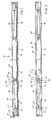
- Fig.1 in einem Längsschnitt eine erfindungsgemäße Dichtungseinrichtung,
- Fig.2 eine Ansicht in Richtung des Pfeiles II in Fig.1,
- Fig.3 einen Querschnitt durch die erfindungsgemäße Dichtungseinrichtung gemäß Fig.1,
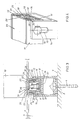
- Fig.4 in perspektivischer Darstellung das eine Ende der erfindungsgemäßen Dichtungseinrichtung.
- Die Dichtungseinrichtung dient zum Abdichten am unteren Rand von Drehtüren, Schiebetüren, Faltwänden und dgl. Sie hat eine Halterung 1 (Fig. 3), die in den Fig.1 und 2 nicht dargestellt ist. Im Ausführungsbeispiel wird die Halterung 1 durch eine U-Schiene gebildet, die sich über die ganze Länge der Dichtungseinrichtung erstreckt. Anstelle der U-Schiene kann die Halterung auch aus einzelnen U-förmigen Schienenabschnitten 1a bestehen (Fig.4), die mit Abstand längs der Dichtungseinrichtung angeordnet sind. Die Halterung 1 liegt mit einem Quersteg 2 auf einem Rohfußboden 3 auf und ist mit Dübeln 4 und dgl. am Fußboden 3 befestigt. Um Neigungen des Fußbodens 3 einfach ausgleichen zu können, sind im Bereich beiderseits der Dübel 4 Stellschrauben 5 in den Quersteg 2 geschraubt. Sie können sich auf dem Fußboden 3 abstützen, so daß duch Heraus- oder Eindrehen dieser Stellschrauben 5 die Halterung 1 bezüglich des Fußbodens 3 einfach justiert werden kann. Im Ausführungsbeispiel ist auf dem Fußboden 3 ein Fußbodenbelag 6 aufgebracht, beispielsweise ein Teppichboden. Sein Oberseite ist mit 7 bezeichnet. Es ist aber auch möglich, die Halterung 1 versenkt direkt im Boden 3 anzuordnen.
- Die Schenkel 8, 9 der Halterung 1 sind aufwärts gerichtet und enden mit Abstand von der Oberseite 7 des Fußbodenbelages 6. Dadurch ist die Halterung 1 verdeckt im Fußbodenbelag 6 untergebracht, so daß sie bei geöffneter Tür 10 nicht stört.
- Zwischen den Schenkeln 8,9 ist ein Führungskörper 11 befestigt, der ebenfalls als U-Schiene ausgebildet ist, deren aufwärts gerichtete Schenkel 12,13 an den Innenseiten der Schenkel 8,9 der Halterung 1 anliegen. Die Schenkel 12, 13 enden in der Oberseite 7 des Fußbodenbelages 6. Ein Quersteg 14 des Führungskörpers 11 liegt mit Abstand oberhalb des Quersteges 2 der Halterung 1. Damit der Führungskörper 11 genau gegenüber der Halterung 1 sowie der Oberseite 7 des Fußbodenbelages 6 ausgerichtet werden kann, sind die Schenkel 8,9 der Halterung 1 mit senkrecht verlaufenden Längsschlitzen 15 (Fig.4) versehen, durch welche in die Schenkel 12, 13 des Führungskörpers 11 geschraubte Schrauben 16 ragen. Nach Lockern der Schrauben 16 kann der Führungskörper 11 relativ zur Halterung 1 verschoben werden, so daß er sich einwandfrei an Ort und Stelle genau ausrichten läßt. Dann werden die Schrauben 16 lediglich fest angezogen, um den Führungskörper fest an der Halterung zu befestigen. Die Längsschlitze 15 sind nahe den freien Enden der Schenkel 7,8 der Halterung 1 vorgesehen. Dies hat zur Folge, daß beim Anziehen der Schrauben 16 die Schenkel gegen den Führungskörper 11 gebogen werden, wodurch die Befestigung des Führungskörpers 11 verbessert wird.
- Im Führungskörper 11 ist unter Zwischenlage einer Dämpfungsschicht 17, die auf dem Quersteg 14 des Führungskörpers aufliegt und beispielsweise durch einen Kunststoffstreifen gebildet sein kann, ein Haltekörper 18 befestigt, der vorteilhaft ebenfalls als U-Schiene ausgebildet ist. Der Haltekörper 18 liegt mit seinem Quersteg 19 auf der Dämpfungsschicht 17 auf. Die Schenkel 20, 21 des Haltekörpers 18 sind aufwärts gerichtet und liegen mit Abstand von den Schenkeln 12,13 des Führungskörpers 11. Auf den freien Enden der Schenkel 20, 21 liegt ein Quersteg 22 eines Dichtungskörpers 23 auf, dessen abwärts gerichtete Schenkel 24,25 zwischen den Schenkeln 12,13 des Führungskörpers 11 und den Schenkeln 20,21 des Haltekörpers mit geringem Spiel liegen (Fig. 3). Die Schenkel 24,25 des Dichtungskörpers 23 enden mit Abstand von der Dämpfungsschicht 17.
- In der in Fig.3 dargestellten Ruhelage liegt der Quersteg 22 des Dichtungskörpers 23 bündig mit der Oberseite 7 des Fußbodenbelages 6. Dadurch ist die Oberseite des Fußbodenbelages 6 im Bereich der Dichtungseinrichtung nicht unterbrochen bzw. nicht mit Absätzen versehen, so daß die Dichtungseinrichtung in der Ruhelage nicht stört.
- An der Unterseite des Quersteges 22 des Dichtungskörpers 23 ist ein im Querschnitt U-förmiges Dichtungselement 26 befestigt, (Fig.3), dessen Schenkel 27,28 in Richtung auf den Quersteg 19 des Haltekörpers 18 divergieren und an den einander zugewandten Innenseiten der Schenkel 20,21 des Haltekörpers 18 unter geringer elastischer Vorspannung anliegen. Das Dichtungselement 26 besteht vorzugsweise aus schalldämpfendem Material, so daß bei geschlossener Tür kein oder nur ein sehr geringer Anteil an Schall über die Dichtungseinrichtung unter der Tür hindurch gelangen kann.
- Nahe den beiden Enden der Dichtungseinrichtung ist auf dem Quersteg 19 des Haltekörpers 18 jeweils eine Betätigungseinrichtung 29,30 angeordnet (Fig.1 und 2), mit denen der Dichtungskörper 23 beim Schließen der Tür 10 in seine Dichtstellung verstellt wird. Die beiden Betätigungseinrichtungen 29,30 sind gleich ausgebildet, jedoch spiegelsymmetrisch zueinander im Haltekörper 18 angeordnet. Im folgenden wird darum nur die Betätigungseinrichtung 29 im einzelnen beschrieben. Sie hat zwei parallel zueinander liegende Hebel 31,32, die mit ihrem vom Ende des Haltekörpers 18 abgewandten Ende an den Enden zweier Schwenkarme 33 und 34 angelenkt sind. Sie liegen an den einander zugewandten Innenseiten der Hebel 31,32 an (Fig.2). Auf der die Hebel 31,32 und die Schwenkarme 33,34 verbindenden Achse 35 sitzt frei drehbar eine Rolle 36.
- Auf dem Quersteg 19 des Haltekörpers 18 ist eine Platte 37 befestigt, die zwei senkrecht abstehende Laschen 38 und 39 trägt. In ihnen ist eine Achse 40 gelagert, auf der die Schwenkarme 33,34 sitzen.
- An einem der Schwenkarme 33,34 greift das eine Ende einer Zugfeder 41 an, die mit ihrem anderen Ende an der Platte 37 oder am Quersteg 19 des Haltekörpers 18 befestigt sein kann. Die Hebel 31,32 sind am anderen Ende an eine Gewindebuchse 42 angelenkt, in die eine Justierschraube 43 eines Ankers 44 eines Elektromagneten 45 geschraubt wird. Der Elektromagnet 45 ist im Haltekörper 18 nahe dessen einem Ende befestigt. Der Anker 44 wird zwischen den Schenkeln 20,21 und den Querstegen 19 und 22 geführt.
- Die Rolle 36 liegt an einer an der Unterseite des Quersteges 22 des Dichtungskörpers 23 befestigten Blattfeder 46 an, deren gegen den Elektromagneten 45 gerichtetes Ende schräg nach unten gegen den Quersteg 19 des Haltekörpers 18 gerichtet ist (Fig.1). Diese Abbiegung des freien Federendes 47 wird durch eine in den Quersteg 22 des Dichtungskörpers 23 geschraubte Stellschraube 48 erreicht, die am Blattfederende 47 anliegt und es je nach eingeschraubter Lage mehr oder weniger weit nach unten gegen den Quersteg 19 des Haltekörpers 18 biegt.
- Der Elektromagnet 45 ist über Zuleitungen 49 mit einem (nicht dargestellten) Schalter verbunden, der im Türrahmen vorgesehen ist und der beim Schließen der Tür 10 betätigt wird.
- Die Figuren 1 bis 4 zeigen die Dichtungseinrichtung in ihrer Ruhelage, in der der Dichtungskörpers 23 mit seinem Quersteg 22 bündig mit der Oberseite 7 des Fußbodenbelages 6 ist. Wird die Tür 10 geschlossen, dann wird am Ende der Schließbewegung der im Türrahmen vorgesehene Schalter für die Elektromagneten 45 betätigt. Dadurch werden die Elektromagneten 45 an den beiden Enden des Haltekörpers 18 erregt und ziehen die Anker 44 gegen die Kraft der Zugfedern 41 an. Über die Hebel 31,32 werden die Schwenkarme 33,34 um die Achse 40 geschwenkt. Die Rollen 36 der beiden Betätigungseinrichtungen 29,30 werden hierbei mitgenommen und laufen auf das schräg nach unten gebogene Ende 47 der Blattfedern 46 auf, wodurch der Dichtungskörper 23 entsprechend der Abwinkelung des Blattfederendes 47 nach oben gegen die Tür 10 verstellt wird. Der Quersteg 22 des Dichtungskörpers 23 gelangt dann in Anlage an einen an der Türunterseite befestigten Dichtungsstreifen 50 (Fig.3), der beispielsweise aus Moosgummi bestehen kann. Dadurch ist eine einwandfreie Abdichtung gewährleistet.
- Mit den Stellschrauben 48 kann der Hubweg des Dichtungskörpers 13 stufenlos und genau eingestellt werden, da sich der Hubweg bei vorgegebenem Stellweg der Hebel 31,32 nach dem Abwinkelungsgrad des freien Endes 47 der Blattfedern 46 bestimmt. Auf diese Weise ist es ohne Schwierigkeiten möglich, an Ort und Stelle den Hubweg des Dichtungkörpers 23 genau einzustellen. Auch nach einer Bearbeitung der Tür 10 kann der Hubweg des Dichtungskörpers 23 mit den Stellschrauben 48 einfach nachgestellt werden.
- Solange die Tür 10 geschlossen ist, bleiben die Elektromagneten 45 erregt und damit der Dichtungskörper 23 in seiner Dichtstellung. Wird die Tür 10 wieder geöffnet, wird der Schalter im Türrahmen freigegeben, wodurch die Elektromagneten 45 abfallen. Die Zugfedern 41 schwenken dann die Schwenkarme 33,34 zurück, wodurch die Anker 44 über die Hebel 31,32 im Führungskörper 18 in die in Fig.1 dargestellte Ausgangslage zurückgeschoben werden.
- Die Rollen 36 kommen von den abgebogenen Enden 47 der Blattfedern 46 frei, woduch der Dichtungskörper 23 unter seinem Eingengewicht wieder nach unten in seine Ruhelage (Fig.3) zurückfällt. Für die Schwenkarme 33,34 ist an den Laschen 38,39 ein Anschlag vorgesehen, der die Endstellung dieser Schwenkarme bestimmt. Ein solcher Anschlag kann aber auch für den Anker 44 vorgesehen sein, woduch ebenfalls die Ausgangslage der Betätigungseinrichtungen 29,30 bestimmt werden kann.
- Um beim Anziehen der Elektromagneten 45 das Anschlaggeräusch der Anker 44 zu verringern, kann zwischen dem Elektromagneten und dem Anker eine (nicht dargestellte) Dämpfung vorgesehen sein, beispielsweise Druckfedern oder ein geeignetes Dämpfungsmaterial. Die Betätigungseinrichtungen 29,30 können an Ort und Stelle auch an die Einbauverhältnisse angepaßt werden. So lassen sich die Hebel 31, 32 beispielsweise leicht auf das erforderliche Maß kürzen. Ferner können die beiden Blattfedern 46 mit den Stellschrauben 48 unterschiedlich gebogen werden, so daß beispielsweise auch bei schräg eingebauten Dichtungseinrichtungen der Dichtungskörper 23 in seiner Dichtlage einwandfrei am Dichtungsstreifen 50 der Tür 10 anliegt.
Claims (16)
dadurch gekennzeichnet, daß das Auslöseglied ein Schalter für mindestens einen Elektromagneten (55) ist, der über mindestens eine einen Anker (44) aufweisende Hubeinrichtung (29,30) mit dem Dichtungskörper (23) verbunden ist.
dadurch gekennzeichnet, daß an den Anker (44) wenigstens ein Verbindungselement (31,32) angelenkt ist, das den Anker (44) mit mindestens einem Schwenkarm (33,34) verbindet.
dadurch gekennzeichnet, daß der Anker (44) in Richtung auf seine Ruhestellung federbelastet ist.
dadurch gekennzeichnet, daß am Schwenkarm (33,34) mindestens eine Zugfeder (41) angreift.
dadurch gekennzeichnet, daß der Elektromagnet (45) im Halte_körper (18) untergebracht ist.
dadurch gekennzeichnet, daß der Dichtungskörper (23) durch eine U-Schiene gebildet ist, deren Quersteg (22) in Dichtstellung an einem Dichtungsstreifen (50) der Tür (10) anliegt.
dadurch gekennzeichnet, daß der Hubweg des Dichtungskörpers (22) einstellbar ist.
dadurch gekennzeichnet, daß die Hubeinrichtung (29,30) wenigstens ein Hubglied (36), vorzugsweise eine Rolle, aufweist, in deren Bewegungsweg wenigstens ein Steigungsglied (46) liegt.
dadurch gekennzeichnet, daß das Hubglied (36) am Schwenkarm (33,34) vorgesehen ist.
dadurch gekennzeichnet, daß das Steigungsglied (46) eine am Dichtungskörper (23) befestigte, elastisch gebogene Blattfeder ist.
dadurch gekennzeichnet, daß die Blattfeder (46) mit eine Stellschraube (48) elastisch biegbar ist.
dadurch gekennzeichnet, daß die Halterung (1) mit dem Dichtungskörper (23) im Fußboden (3,6) untergebracht ist.
dadurch gekennzeichnet, daß der Dichtungskörper (23) in seiner Ruhestellung auf dem Haltekörper (18) aufliegt.
dadurch gekennzeichnet, daß der Dichtungskörper (23) relativ sur Halterung (1) einstellbar ist.
dadurch gekennzeichnet, daß an der Halterung (1) mindestens ein Führungskörper (11) verstellbar befestigt ist, der den Haltekörper (18) und den Dichtungskörper (23) trägt.
Priority Applications (1)
| Application Number | Priority Date | Filing Date | Title |
|---|---|---|---|
| AT89105081T ATE95881T1 (de) | 1988-03-23 | 1989-03-22 | Dichtungseinrichtung fuer tueren. |
Applications Claiming Priority (2)
| Application Number | Priority Date | Filing Date | Title |
|---|---|---|---|
| DE3809669A DE3809669C2 (de) | 1988-03-23 | 1988-03-23 | Dichtungseinrichtung für Türen |
| DE3809669 | 1988-03-23 |
Publications (3)
| Publication Number | Publication Date |
|---|---|
| EP0334307A2 true EP0334307A2 (de) | 1989-09-27 |
| EP0334307A3 EP0334307A3 (en) | 1990-06-06 |
| EP0334307B1 EP0334307B1 (de) | 1993-10-13 |
Family
ID=6350407
Family Applications (1)
| Application Number | Title | Priority Date | Filing Date |
|---|---|---|---|
| EP89105081A Expired - Lifetime EP0334307B1 (de) | 1988-03-23 | 1989-03-22 | Dichtungseinrichtung für Türen |
Country Status (3)
| Country | Link |
|---|---|
| EP (1) | EP0334307B1 (de) |
| AT (1) | ATE95881T1 (de) |
| DE (2) | DE3809669C2 (de) |
Cited By (9)
| Publication number | Priority date | Publication date | Assignee | Title |
|---|---|---|---|---|
| DE3935790A1 (de) * | 1989-10-27 | 1991-05-02 | Hahn Gmbh & Co Kg Dr | Automatische bodendichtung fuer eine tuer |
| EP0424708A2 (de) * | 1989-10-27 | 1991-05-02 | Dr. Hahn GmbH & Co. KG | Automatische Bodendichtung für eine Tür |
| EP0489537A1 (de) * | 1990-12-05 | 1992-06-10 | Draftex Industries Limited | Dichtungsvorrichtung |
| US5253453A (en) * | 1990-12-12 | 1993-10-19 | Draftex Industries Limited | Sealing arrangements |
| EP0609755A1 (de) * | 1993-01-29 | 1994-08-10 | Firma F. Athmer | Bodenseitige Dichtungsvorrichtung für eine Tür |
| US5339488A (en) * | 1990-11-13 | 1994-08-23 | Draftex Industries Limited | Sealing and wiping arrangement including inflatable chamber |
| DE20005376U1 (de) * | 2000-03-22 | 2001-07-26 | Kross Manfred | Bodendichtung für ein Türblatt |
| EP1944457A3 (de) * | 2007-01-09 | 2011-04-13 | F. Athmer OHG | Dichtungsanordnung mit ein- und ausschaltbarer Dichtung |
| EP2682556A1 (de) | 2012-07-02 | 2014-01-08 | Planet GDZ AG | Dichtungsanordnung für eine Tür oder ein Fenster |
Families Citing this family (1)
| Publication number | Priority date | Publication date | Assignee | Title |
|---|---|---|---|---|
| DE10134632A1 (de) * | 2001-07-17 | 2003-07-17 | Micro Mechatronic Technologies | Dichtungseinrichtung, insbesondere für eine Tür oder ein Fenster |
Citations (7)
| Publication number | Priority date | Publication date | Assignee | Title |
|---|---|---|---|---|
| DE900492C (de) * | 1952-02-02 | 1953-12-28 | Hans Willi | Abschlussvorrichtung an einer Tuer ohne Schwelle |
| US2870495A (en) * | 1954-09-16 | 1959-01-27 | Wayne Iron Works | Closure sealing device |
| FR1434355A (fr) * | 1965-02-25 | 1966-04-08 | Plinthe automatique | |
| DE2537899A1 (de) * | 1974-08-27 | 1976-03-11 | Schweizer Ag E | Traeger fuer eine schiene, insbesondere fuer eine tuerschwelle oder einen blendrahmen |
| DE2509958A1 (de) * | 1975-03-07 | 1976-09-23 | Wagenbrenner Helmut | Abdichtungsvorrichtung fuer fugen zwischen beweglichen bauteilen |
| US4519165A (en) * | 1984-01-05 | 1985-05-28 | F. Athmer | Sealing device for the bottom of a door |
| EP0216022B1 (de) * | 1985-09-21 | 1990-04-25 | Harry Frey | Türdichtung vorzugsweise für schwellenlose Türen |
-
1988
- 1988-03-23 DE DE3809669A patent/DE3809669C2/de not_active Expired - Fee Related
-
1989
- 1989-03-22 AT AT89105081T patent/ATE95881T1/de active
- 1989-03-22 EP EP89105081A patent/EP0334307B1/de not_active Expired - Lifetime
- 1989-03-22 DE DE89105081T patent/DE58905866D1/de not_active Expired - Fee Related
Patent Citations (7)
| Publication number | Priority date | Publication date | Assignee | Title |
|---|---|---|---|---|
| DE900492C (de) * | 1952-02-02 | 1953-12-28 | Hans Willi | Abschlussvorrichtung an einer Tuer ohne Schwelle |
| US2870495A (en) * | 1954-09-16 | 1959-01-27 | Wayne Iron Works | Closure sealing device |
| FR1434355A (fr) * | 1965-02-25 | 1966-04-08 | Plinthe automatique | |
| DE2537899A1 (de) * | 1974-08-27 | 1976-03-11 | Schweizer Ag E | Traeger fuer eine schiene, insbesondere fuer eine tuerschwelle oder einen blendrahmen |
| DE2509958A1 (de) * | 1975-03-07 | 1976-09-23 | Wagenbrenner Helmut | Abdichtungsvorrichtung fuer fugen zwischen beweglichen bauteilen |
| US4519165A (en) * | 1984-01-05 | 1985-05-28 | F. Athmer | Sealing device for the bottom of a door |
| EP0216022B1 (de) * | 1985-09-21 | 1990-04-25 | Harry Frey | Türdichtung vorzugsweise für schwellenlose Türen |
Cited By (10)
| Publication number | Priority date | Publication date | Assignee | Title |
|---|---|---|---|---|
| DE3935790A1 (de) * | 1989-10-27 | 1991-05-02 | Hahn Gmbh & Co Kg Dr | Automatische bodendichtung fuer eine tuer |
| EP0424708A2 (de) * | 1989-10-27 | 1991-05-02 | Dr. Hahn GmbH & Co. KG | Automatische Bodendichtung für eine Tür |
| EP0424708B1 (de) * | 1989-10-27 | 1996-07-03 | Dr. Hahn GmbH & Co. KG | Automatische Bodendichtung für eine Tür |
| US5339488A (en) * | 1990-11-13 | 1994-08-23 | Draftex Industries Limited | Sealing and wiping arrangement including inflatable chamber |
| EP0489537A1 (de) * | 1990-12-05 | 1992-06-10 | Draftex Industries Limited | Dichtungsvorrichtung |
| US5253453A (en) * | 1990-12-12 | 1993-10-19 | Draftex Industries Limited | Sealing arrangements |
| EP0609755A1 (de) * | 1993-01-29 | 1994-08-10 | Firma F. Athmer | Bodenseitige Dichtungsvorrichtung für eine Tür |
| DE20005376U1 (de) * | 2000-03-22 | 2001-07-26 | Kross Manfred | Bodendichtung für ein Türblatt |
| EP1944457A3 (de) * | 2007-01-09 | 2011-04-13 | F. Athmer OHG | Dichtungsanordnung mit ein- und ausschaltbarer Dichtung |
| EP2682556A1 (de) | 2012-07-02 | 2014-01-08 | Planet GDZ AG | Dichtungsanordnung für eine Tür oder ein Fenster |
Also Published As
| Publication number | Publication date |
|---|---|
| DE3809669C2 (de) | 1996-10-24 |
| ATE95881T1 (de) | 1993-10-15 |
| EP0334307B1 (de) | 1993-10-13 |
| EP0334307A3 (en) | 1990-06-06 |
| DE3809669A1 (de) | 1989-10-12 |
| DE58905866D1 (de) | 1993-11-18 |
Similar Documents
| Publication | Publication Date | Title |
|---|---|---|
| EP0509961B1 (de) | Dichtungsvorrichtung, insbesondere für Türflügel | |
| EP3452680B1 (de) | Dichtungsvorrichtung | |
| EP3452681B1 (de) | Dichtungsvorrichtung für eine schiebetür | |
| DE10014760B4 (de) | Heckscheibenrollo mit gefederten Rollen | |
| EP2050907A2 (de) | Dämpfungs- und Einziehvorrichtung | |
| DE3809669C2 (de) | Dichtungseinrichtung für Türen | |
| DE19806405A1 (de) | Einseitig auslösbare Türdichtungsvorrichtung | |
| DE19516588C1 (de) | Feststellvorrichtung für Fenster, Türen od. dgl. | |
| CH627228A5 (en) | Automatic door seal for doors without thresholds | |
| DE19533153C2 (de) | Schiebetür mit Notöffnungs- oder Notschließeinrichtung | |
| EP0468223A2 (de) | Falttor | |
| WO2019158439A1 (de) | Absenkbare einbruchsicherung | |
| EP1064448B1 (de) | Schiebetür mit notöffnungs- oder notschliesseinrichtung | |
| EP0019076B1 (de) | Führungsanordnung zum linearen Verstellen mindestens eines an einem Träger angeordneten Gegenstandes, insbesondere zur Parallelverstellung von Möbeleinschüben | |
| EP2871312B1 (de) | Spaltlüftungsanordnung für eine Schiebetür oder -fenster und Schiebetür oder -fenster | |
| EP4144945A1 (de) | Schiebetürsystem, schiebetür und puffervorrichtung | |
| EP3859110A1 (de) | Schiebetürbeschlag und verfahren zum bewegen einer steuereinrichtung | |
| EP1001126B1 (de) | Fixiervorrichtung | |
| DE3015836A1 (de) | Sicherheitsvorrichtung fuer kraftfahrzeugschiebedaecher u.dgl. | |
| EP2896773B1 (de) | Schließfolgeregelung | |
| EP3667010B1 (de) | Anschlagvorrichtung für eine automatische türdichtung, insbesondere für eine pivot- oder pendeltür, anordnung aus einer automatischen türdichtung und einer anschlagvorrichtung | |
| CH465830A (de) | Türabdichtung gegenüber einem schwellenlosen Boden | |
| EP3770370B1 (de) | Türdichtungsanordnung | |
| DE1683060C3 (de) | Dichtungsanordnung für schwellenlose Türen | |
| DE19725357A1 (de) | Schiebetürschließeinrichtung |
Legal Events
| Date | Code | Title | Description |
|---|---|---|---|
| PUAI | Public reference made under article 153(3) epc to a published international application that has entered the european phase |
Free format text: ORIGINAL CODE: 0009012 |
|
| AK | Designated contracting states |
Kind code of ref document: A2 Designated state(s): AT BE CH DE ES FR GB GR IT LI LU NL SE |
|
| PUAL | Search report despatched |
Free format text: ORIGINAL CODE: 0009013 |
|
| AK | Designated contracting states |
Kind code of ref document: A3 Designated state(s): AT BE CH DE ES FR GB GR IT LI LU NL SE |
|
| 17P | Request for examination filed |
Effective date: 19901206 |
|
| 17Q | First examination report despatched |
Effective date: 19910726 |
|
| RAP1 | Party data changed (applicant data changed or rights of an application transferred) |
Owner name: WEISSSCHAEDEL, HEDWIG |
|
| RIN1 | Information on inventor provided before grant (corrected) |
Inventor name: WEISSSCHAEDEL, HANS |
|
| GRAA | (expected) grant |
Free format text: ORIGINAL CODE: 0009210 |
|
| AK | Designated contracting states |
Kind code of ref document: B1 Designated state(s): AT BE CH DE ES FR GB GR IT LI LU NL SE |
|
| PG25 | Lapsed in a contracting state [announced via postgrant information from national office to epo] |
Ref country code: IT Free format text: LAPSE BECAUSE OF FAILURE TO SUBMIT A TRANSLATION OF THE DESCRIPTION OR TO PAY THE FEE WITHIN THE PRE;WARNING: LAPSES OF ITALIAN PATENTS WITH EFFECTIVE DATE BEFORE 2007 MAY HAVE OCCURRED AT ANY TIME BEFORE 2007. THE CORRECT EFFECTIVE DATE MAY BE DIFFERENT FROM THE ONE RECORDED.SCRIBED TIME-LIMIT Effective date: 19931013 Ref country code: GB Effective date: 19931013 Ref country code: GR Free format text: LAPSE BECAUSE OF FAILURE TO SUBMIT A TRANSLATION OF THE DESCRIPTION OR TO PAY THE FEE WITHIN THE PRESCRIBED TIME-LIMIT Effective date: 19931013 Ref country code: ES Free format text: THE PATENT HAS BEEN ANNULLED BY A DECISION OF A NATIONAL AUTHORITY Effective date: 19931013 Ref country code: SE Effective date: 19931013 |
|
| REF | Corresponds to: |
Ref document number: 95881 Country of ref document: AT Date of ref document: 19931015 Kind code of ref document: T |
|
| ET | Fr: translation filed | ||
| REF | Corresponds to: |
Ref document number: 58905866 Country of ref document: DE Date of ref document: 19931118 |
|
| GBV | Gb: ep patent (uk) treated as always having been void in accordance with gb section 77(7)/1977 [no translation filed] |
Effective date: 19931013 |
|
| EPTA | Lu: last paid annual fee | ||
| PLBE | No opposition filed within time limit |
Free format text: ORIGINAL CODE: 0009261 |
|
| STAA | Information on the status of an ep patent application or granted ep patent |
Free format text: STATUS: NO OPPOSITION FILED WITHIN TIME LIMIT |
|
| 26N | No opposition filed | ||
| PGFP | Annual fee paid to national office [announced via postgrant information from national office to epo] |
Ref country code: FR Payment date: 19970320 Year of fee payment: 9 |
|
| PGFP | Annual fee paid to national office [announced via postgrant information from national office to epo] |
Ref country code: BE Payment date: 19970325 Year of fee payment: 9 |
|
| PGFP | Annual fee paid to national office [announced via postgrant information from national office to epo] |
Ref country code: NL Payment date: 19970331 Year of fee payment: 9 |
|
| PGFP | Annual fee paid to national office [announced via postgrant information from national office to epo] |
Ref country code: CH Payment date: 19970407 Year of fee payment: 9 |
|
| PGFP | Annual fee paid to national office [announced via postgrant information from national office to epo] |
Ref country code: LU Payment date: 19970410 Year of fee payment: 9 |
|
| PG25 | Lapsed in a contracting state [announced via postgrant information from national office to epo] |
Ref country code: LU Free format text: LAPSE BECAUSE OF NON-PAYMENT OF DUE FEES Effective date: 19980322 |
|
| PG25 | Lapsed in a contracting state [announced via postgrant information from national office to epo] |
Ref country code: CH Free format text: LAPSE BECAUSE OF NON-PAYMENT OF DUE FEES Effective date: 19980331 Ref country code: FR Free format text: THE PATENT HAS BEEN ANNULLED BY A DECISION OF A NATIONAL AUTHORITY Effective date: 19980331 Ref country code: LI Free format text: LAPSE BECAUSE OF NON-PAYMENT OF DUE FEES Effective date: 19980331 Ref country code: BE Free format text: LAPSE BECAUSE OF NON-PAYMENT OF DUE FEES Effective date: 19980331 |
|
| PGFP | Annual fee paid to national office [announced via postgrant information from national office to epo] |
Ref country code: AT Payment date: 19980331 Year of fee payment: 10 |
|
| PGFP | Annual fee paid to national office [announced via postgrant information from national office to epo] |
Ref country code: DE Payment date: 19980523 Year of fee payment: 10 |
|
| BERE | Be: lapsed |
Owner name: WEISSSCHADEL HEDWIG Effective date: 19980331 |
|
| PG25 | Lapsed in a contracting state [announced via postgrant information from national office to epo] |
Ref country code: NL Free format text: LAPSE BECAUSE OF NON-PAYMENT OF DUE FEES Effective date: 19981001 |
|
| REG | Reference to a national code |
Ref country code: CH Ref legal event code: PL |
|
| NLV4 | Nl: lapsed or anulled due to non-payment of the annual fee |
Effective date: 19981001 |
|
| REG | Reference to a national code |
Ref country code: FR Ref legal event code: ST |
|
| PG25 | Lapsed in a contracting state [announced via postgrant information from national office to epo] |
Ref country code: AT Free format text: LAPSE BECAUSE OF NON-PAYMENT OF DUE FEES Effective date: 19990322 |
|
| PG25 | Lapsed in a contracting state [announced via postgrant information from national office to epo] |
Ref country code: DE Free format text: LAPSE BECAUSE OF NON-PAYMENT OF DUE FEES Effective date: 20000101 |