EP0332861B1 - Lagerung für eine Motor-Getriebeeinheit - Google Patents
Lagerung für eine Motor-Getriebeeinheit Download PDFInfo
- Publication number
- EP0332861B1 EP0332861B1 EP89102577A EP89102577A EP0332861B1 EP 0332861 B1 EP0332861 B1 EP 0332861B1 EP 89102577 A EP89102577 A EP 89102577A EP 89102577 A EP89102577 A EP 89102577A EP 0332861 B1 EP0332861 B1 EP 0332861B1
- Authority
- EP
- European Patent Office
- Prior art keywords
- bearing
- engine
- gearbox
- torsion bar
- unit
- Prior art date
- Legal status (The legal status is an assumption and is not a legal conclusion. Google has not performed a legal analysis and makes no representation as to the accuracy of the status listed.)
- Expired - Lifetime
Links
Images
Classifications
-
- B—PERFORMING OPERATIONS; TRANSPORTING
- B60—VEHICLES IN GENERAL
- B60K—ARRANGEMENT OR MOUNTING OF PROPULSION UNITS OR OF TRANSMISSIONS IN VEHICLES; ARRANGEMENT OR MOUNTING OF PLURAL DIVERSE PRIME-MOVERS IN VEHICLES; AUXILIARY DRIVES FOR VEHICLES; INSTRUMENTATION OR DASHBOARDS FOR VEHICLES; ARRANGEMENTS IN CONNECTION WITH COOLING, AIR INTAKE, GAS EXHAUST OR FUEL SUPPLY OF PROPULSION UNITS IN VEHICLES
- B60K5/00—Arrangement or mounting of internal-combustion or jet-propulsion units
- B60K5/12—Arrangement of engine supports
- B60K5/1208—Resilient supports
- B60K5/1216—Resilient supports characterised by the location of the supports relative to the motor or to each other
-
- B—PERFORMING OPERATIONS; TRANSPORTING
- B60—VEHICLES IN GENERAL
- B60K—ARRANGEMENT OR MOUNTING OF PROPULSION UNITS OR OF TRANSMISSIONS IN VEHICLES; ARRANGEMENT OR MOUNTING OF PLURAL DIVERSE PRIME-MOVERS IN VEHICLES; AUXILIARY DRIVES FOR VEHICLES; INSTRUMENTATION OR DASHBOARDS FOR VEHICLES; ARRANGEMENTS IN CONNECTION WITH COOLING, AIR INTAKE, GAS EXHAUST OR FUEL SUPPLY OF PROPULSION UNITS IN VEHICLES
- B60K5/00—Arrangement or mounting of internal-combustion or jet-propulsion units
- B60K5/04—Arrangement or mounting of internal-combustion or jet-propulsion units with the engine main axis, e.g. crankshaft axis, transversely to the longitudinal centre line of the vehicle
-
- F—MECHANICAL ENGINEERING; LIGHTING; HEATING; WEAPONS; BLASTING
- F02—COMBUSTION ENGINES; HOT-GAS OR COMBUSTION-PRODUCT ENGINE PLANTS
- F02F—CYLINDERS, PISTONS OR CASINGS, FOR COMBUSTION ENGINES; ARRANGEMENTS OF SEALINGS IN COMBUSTION ENGINES
- F02F7/00—Casings, e.g. crankcases
- F02F7/006—Camshaft or pushrod housings
Definitions
- the invention relates to a bearing for a motor-gear unit according to the preamble of claim 1.
- the object of the invention is to provide a bearing for a drive unit arranged transversely in the vehicle, which ensures optimized vibration isolation between the drive unit and the body of the vehicle.
- the engine and gearbox bearings are arranged and specifically coordinated so that negative effects on driving comfort, such as. B. load changes and rigid body vibrations caused by uneven roads.
- the bearings are arranged relatively close to a horizontal plane running through the center of gravity, as a result of which vibration forms that occur can be effectively decoupled.
- the relatively large distance between the bearings leads to advantageous high natural frequencies of the rigid body rotations.
- the positioning of the engine and gearbox bearing approximately at a level defined by the center of gravity results in an advantageous suspension of the unit on the vehicle body, such that the two bearings - one on the front of the engine and the other approximately on the front of the gearbox - result in a so-called pendulum mounting, these two bearings then essentially only bear the weight of the unit, while the torque supports then only absorb the reaction forces of the drive torques, which act essentially in the vertical direction.
- An idle shiver is isolated by bearings of the torque arms which are appropriately designed in the horizontal direction.
- the separate absorption of the individual loads of the unit during operation makes it possible to design the stiffnesses of the engine and gearbox bearings in a defined manner in the transverse, longitudinal and vertical directions for each task.
- the upper torque arm is supported on the engine side by means of a support arm which is detachably connected to a cylinder head cover, as a result of which a storage location is achieved for the upper torque arm that lies with a large base to the lower torque arm.
- the drive unit 1 which essentially consists of an internal combustion engine 2 and a gearbox 3, is connected to the vehicle body via a motor mount 4 and a gearbox mount 5 and by means of two torque supports 7 and 8 supported.
- the motor mount 4 and the gearbox mount 5 are arranged slightly above a horizontal plane 9 running through the center of gravity S (FIG. 1), with a connecting line 10 between these two bearings 4 and 5 running through the center of gravity S in plan view (FIG. 2) .
- the bearings 4 and 5 are held by short rigid support arms 12, 13 as close as possible to the long sides 14, 15 and the end of the unit 1 in order to achieve a favorable vibration behavior.
- the bearings 4, 5 are preferably fastened in areas of the unit 1 which are favorable for vibrations, and the vehicle body is supported in relatively stiff areas.
- the engine mount 4 can be designed as a hydraulic mount and the gearbox mount 5 as a rubber flange mount.
- the identifiers of the conventional flange stop are made relatively hard in the vertical and transverse directions and less hard in the longitudinal direction, so that the bearing 5 holds the unit 1 in position when cornering.
- the engine mount 4 is designed with a softer identifier in all directions than the gear mount 5.
- the bearings 4 and 5 are due to the location of their connecting line 10 in the area of the center of gravity S with respect to the identifier in longitudinal, transverse and The vertical direction can be defined without affecting other essential criteria.
- the hydraulic bearing (motor bearing 4) is used to dampen a rolling movement of the assembly 1 around the transmission bearing 5.
- the torque supports 7 and 8 are arranged at a relatively large height distance h from one another above and below the horizontal focal plane 9 from the gearbox bearing 5 on the opposite side of the unit 1 on the motor housing.
- the two torque supports 7 and 8 extend approximately horizontally on both sides of a cylinder longitudinal plane 16 and are held in bearings 18 and 17 and on the motor housing in bearings 19 and 20 for the vehicle body.
- the bearing 19 of the upper torque arm 7 is laterally on the cylinder head cover 40 and the further bearing 20 of the lower torque arm 8 is arranged opposite on a long side 14 of the engine housing 41.
- the torque supports 7 and 8 run parallel to one another in the view according to FIG. 3, the torque support 7 being located between a structural wall 21 and the unit 1 above a bearing level 22 of the engine and transmission bearings 4 and 5 and the further torque support 8 between one Front end wall 23 and the unit 1 is arranged below a horizontal plane 25 running through the crankshaft 24.
- the torque arms 7 and 8 are - as seen in FIG. 2 in plan view - mounted in a common transverse engine plane Y-Y to each other.
- the mounting on the body for the bearing 18 of the overhead torque arm 7 is provided with a horizontally running adjustment slot 26, which gives the possibility of compensating for tolerances.
- the bearings 19 and 20 of the two torque arms 7 and 8 contain a vertically oriented pressure cushion 27 with a stop part 27a acting in the vehicle direction, which is designed such that a clearance (distance c) remains between this stop part 27a and the surrounding bearing shell 28 in the idle state.
- This free space between the stop part 27a and the bearing shell 28 serves to decouple an idle shiver.
- the stop element 27a bears against the bearing shell 28.
- the pressure pad ensures that a low spring stiffness is increased after small vibrations.
- the torque supports 7 and 8 are articulated in the bearings 17, 19 and 18, 20, that is, the supports 7 and 8 can pivot in the arrow directions 29, 30, the bearings 19 and 18 then being subjected to rotation.
Landscapes
- Engineering & Computer Science (AREA)
- Chemical & Material Sciences (AREA)
- Combustion & Propulsion (AREA)
- Transportation (AREA)
- Mechanical Engineering (AREA)
- Arrangement Or Mounting Of Propulsion Units For Vehicles (AREA)
- Vibration Prevention Devices (AREA)
Description
- Die Erfindung bezieht sich auf eine Lagerung für eine Motor-Getriebeeinheit nach dem Oberbegriff des Anspruchs 1.
- Aus der DE-OS 34 02 100 ist eine schwingungsisolierende Lageranordnung für ein querliegendes Fahrzeug- Antriebsaggregat mit einer Drehmomentabstützung bekannt, wobei es über drei Lager aufbauseitig gehalten und durch zwei Drehmomentstützen, die zu einer Seite des Aggregats angeordnet sind, abgestützt wird.
- Aufgabe der Erfindung ist es, eine Lagerung für ein querliegend im Fahrzeug angeordnetes Antriebsaggregat zu schaffen, die eine optimierte Schwingungsisolierung zwischen Antriebsaggregat und Aufbau des Fahrzeugs gewährleistet.
- Diese Aufgabe wird erfindungsgemäß durch die kennzeichnenden Merkmale des Anspruchs 1 gelöst. Weitere vorteilhafte Merkmale beinhalten die Unteransprüche.
- Durch die spezielle Anordnung und Ausbildung eines Motor- und Getriebelagers und von Drehmomentstützen und deren Lager wird eine Aufhängung für ein quereingebautes Antriebsaggregat eines Fahrzeugs erzielt, durch das eine Funktionstrennung von Gewichtsaufnahme und Drehmomentabstützung und hieraus resultierend eine getrennte Abstimmbarkeit einzelner Eigenschwingungsfrequenzen möglich wird. Insbesondere weist eine derartige Aufhängung im wesentlichen folgende Vorteile auf:
- - Ein guter Fahrkomfort durch vorteilhafte getrennte Abstimmöglichkeit für ein Motorstuckern und Lastwechselreaktionen;
- - Eine Abkopplung eines Leerlaufzitterns durch eine weiche Federkennung der Drehmomentstützlager bei relativ kleinen Schwingwegen;
- - Ein geringes Innengeräusch durch geringe dynamische Steifigkeiten der beiden Traglager (Motor-und Getriebelager).
- Das Motor- und Getriebelager sind so angeordnet und gezielt abgestimmt, daß sich negativ auf den Fahrkomfort auswirkende Einflüsse, wie z. B. Lastwechselstöße und Starrkörperschwingungen durch Straßenunebenheiten minimiert werden. Hierzu sind die Lager relativ nahe einer durch den Schwerpunkt verlaufenden Horizontalebene angeordnet, wodurch auftretende Schwingungsformen wirksam entkoppelt werden können. Außerdem führt der relativ große Abstand der Lager zueinander zu vorteilhaften hohen Eigenfrequenzen der Starrkörperdrehungen.
- Die Positionierung des Motor- und Getriebelagers etwa in Höhe einer durch den Schwerpunkt gelegten Ebene ergibt eine vorteilhafte Aufhängung des Aggregats am Fahrzeugaufbau, derart, daß die beiden Lager - das eine an der Motorstirnseite und das weitere etwa an der Getriebestirnseite - eine sogenannte Pendellagerung ergeben, wobei diese beiden Lager dann im wesentlichen nur noch das Aggregatgewicht tragen, während die Drehmomentstützen dann nur noch die Reaktionskräfte der Antriebsmomente aufnehmen, die im wesentlichen in vertikaler Richtung wirken. Eine Isolation eines Leerlaufzitterns erfolgt durch in horizontaler Richtung entsprechend ausgebildete Lager der Drehmomentstützen. Durch die getrennte Aufnahme der einzelnen auftretenden Belastungen der Einheit im Betrieb wird es möglich, die Steifigkeiten des Motor-und Getriebelagers in Quer- Längs- und Hochrichtung definiert für je eine Aufgabe auszulegen.
- Die motorseitige Abstützung der oberen Drehmomentstütze erfolgt über einen Tragarm, der mit einem Zylinderkopfdeckel lösbar verbunden ist, wodurch für die obere Drehmomentstütze ein Lagerort erzielt wird, der mit großer Basis zur unteren Drehmomentstütze liegt.
- Ein Ausführungsbeispiel der Erfindung ist in der Zeichnung dargestellt und wird im folgenden näher beschrieben.
- Es zeigen:
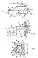
- Fig. 1 eine Rückansicht einer schematisch dargestellten Motor-Getriebeeinheit mit Lagern und Drehmomentstützen,
- Fig. 2 eine Draufsicht auf die Einheit gemäß Fig. 1,
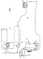
- Fig. 3 eine Ansicht in Pfeilrichtung Z gemäß Fig. 1 gesehen,
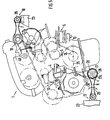
- Fig. 4 eine Vorderansicht auf die Einheit mit Motor- und Getriebelager sowie Drehmomentstützen und
- Fig. 5 eine Stirnansicht auf die Einheit in Pfeilrichtung X der Fig. 1 gesehen.
- Wie aus den schematischen Darstellungen der Fig. 1 bis 3 zu erkennen ist, wird das Antriebsaggregat 1, das im wesentlichen aus einer Brennkraftmaschine 2 und einem Getriebe 3 besteht, über ein Motorlager 4 und einem Getriebelager 5 mit dem Fahrzeugaufbau verbunden und mittels zweier Drehmomentstützen 7 und 8 abgestützt.
- Das Motorlager 4 sowie das Getriebelager 5 sind geringfügig oberhalb einer durch den Schwerpunkt S verlaufenden horizontalen Ebene 9 angeordnet (Fig. 1) wobei eine Verbindungslinie 10 zwischen diesen beiden Lagern 4 und 5 in der Draufsicht (Fig. 2) nahezu durch den Schwerpunkt S verläuft.
- Die Lager 4 und 5 sind über kurze steife Tragarme 12, 13 möglichst nahe der Längsseiten 14, 15 und endseitig des Aggregats 1 gehalten um ein günstiges Schwingungsverhalten zu erzielen. Um Anregungen des Fahrzeugaufbaus zu vermeiden sind die Lager 4, 5 vorzugsweise in schwingungsgünstigen Bereichen des Aggregats 1 befestigt und eine Abstützung zum Fahrzeugaufbau erfolgt in relativ steifen Bereichen.
- Das Motorlager 4 kann als Hydrolager und das Getriebelager 5 als Gummiflanschlager ausgeführt sein. Die Kennungen des konventionellen Flanschlagers sind in Hoch- und Querrichtung relativ hart und in Längsrichtung weniger hart ausgeführt, so daß das Lager 5 die Einheit 1 bei Kurvenfahrt in Lage hält. Dagegen ist das Motorlager 4 in allen Richtungen mit einer weicheren Kennung ausgeführt als das Getriebelager 5.
- Die Lager 4 und 5 sind aufgrund der Lage ihrer Verbindungslinie 10 im Bereich des Schwerpunktes S in bezug auf die Kennung in Längs- Quer- und Hochrichtung definiert abstimmbar, ohne daß andere wesentliche Kriterien beeinflußt werden. Insbesondere wird das Hydrolager (Motorlager 4) zur Bedämpfung einer Rollbewegung des Aggregats 1 um das Getriebelager 5 mit herangezogen.
- Die Drehmomentstützen 7 und 8 sind mit einem relativ großen Höhenabstand h zueinander oberhalb und unterhalb der horizontalen Schwerpunktebene 9 entfernt vom Getriebelager 5 auf der gegenüberliegenden Seite der Einheit 1 am Motorgehäuse angeordnet.
- Zur Abstützung von Reaktionsmomenten der Brennkraftmaschine 2 erstrecken sich die beiden Drehmomentstützen 7 und 8 etwa horizontal zu beiden Seiten einer Zylinderlängsebene 16 und sind zum Fahrzeugaufbau in Lagern 18 und 17 und am Motorgehäuse in Lagern 19 und 20 gehalten.
- Das Lager 19 der obenliegenden Drehmomentstütze 7 ist seitlich am Zylinderkopfdeckel 40 und das weitere Lager 20 der untenliegenden Drehmomentstütze 8 ist gegenüberliegend an einer Längsseite 14 des Motorgehäuses 41 angeordnet. Die Drehmomentstützen 7 und 8 verlaufen - in der Ansicht gemäß Fig. 3 - parallel zueinander, wobei die Drehmomentstütze 7 zwischen einer Aufbauwand 21 und dem Aggregat 1 oberhalb einer Lagerebene 22 des Motor- und Getriebelagers 4 und 5 liegt und die weitere Drehmomentstütze 8 zwischen einer Frontstirnwand 23 und dem Aggregat 1 unterhalb einer durch die Kurbelwelle 24 verlaufenden horizontalen Ebene 25 angeordnet ist. Die Drehmomentstützen 7 und 8 sind - gemäß Fig. 2 in Draufsicht gesehen - in einer gemeinsamen Motor- Querebene Y-Y zueinander gelagert.
- Die aufbauseitige Befestigung für das Lager 18 der obenliegenden Drehmomentstütze 7 ist mit einem horizontal verlaufenden Einstellschlitz 26 versehen, der die Möglichkeit gibt, Toleranzen auszugleichen. Die Lager 19 und 20 der beiden Drehmomentstützen 7 und 8 enthalten ein vertikal ausgerichtetes Druckpolster 27 mit einem in Fahrzeugqeurrichtung wirkendem Anschlagteil 27a, welches so ausgebildet ist, daß zwischen diesem Anschlagteil 27a und der umgebenden Lagerschale 28 im Ruhezustand ein Freiraum (Abstand c) verbleibt. Dieser Freiraum zwischen Anschlagteil 27a und Lagerschale 28 dient zum Entkoppeln eines Leerlaufzitterns. Bei einer Abstützung eines Drehmoments liegt das Anschlagelement 27a an der Lagerschale 28 an. Durch das Druckpolster wird erreicht, daß eine niedrige Federsteifigkeit nach kleinen Schwingungen erhöht wird.
- Die Drehmomentstützen 7 und 8 sind in den Lagern 17, 19 und 18, 20 gelenkig gelagert, daß heißt, die Stützen 7 und 8 können sich in die Pfeilrichtungen 29, 30 pendelnd verschwenken, wobei die Lager 19 und 18 dann auf Verdrehung beansprucht werden.
Claims (10)
Applications Claiming Priority (2)
| Application Number | Priority Date | Filing Date | Title |
|---|---|---|---|
| DE3808762 | 1988-03-16 | ||
| DE3808762A DE3808762A1 (de) | 1988-03-16 | 1988-03-16 | Lagerung fuer eine motor-getriebeeinheit |
Publications (2)
| Publication Number | Publication Date |
|---|---|
| EP0332861A1 EP0332861A1 (de) | 1989-09-20 |
| EP0332861B1 true EP0332861B1 (de) | 1990-09-12 |
Family
ID=6349867
Family Applications (1)
| Application Number | Title | Priority Date | Filing Date |
|---|---|---|---|
| EP89102577A Expired - Lifetime EP0332861B1 (de) | 1988-03-16 | 1989-02-15 | Lagerung für eine Motor-Getriebeeinheit |
Country Status (4)
| Country | Link |
|---|---|
| EP (1) | EP0332861B1 (de) |
| DE (2) | DE3808762A1 (de) |
| ES (1) | ES2011221B3 (de) |
| RU (1) | RU2041081C1 (de) |
Families Citing this family (20)
| Publication number | Priority date | Publication date | Assignee | Title |
|---|---|---|---|---|
| KR930006596B1 (ko) * | 1990-01-31 | 1993-07-21 | 렝크 악티엔게젤샤프트 | 무한궤도차량용 구동시스템 |
| DE4009995C3 (de) * | 1990-03-02 | 1999-02-11 | Metzeler Gimetall Ag | Verfahren zur schwingungsisolierenden Lagerung einer Motor-Getriebeeinheit und Lagerung nach diesem Verfahren |
| JP3084997B2 (ja) * | 1993-01-22 | 2000-09-04 | スズキ株式会社 | 自動車用エンジンのマウント装置 |
| JP3341638B2 (ja) * | 1997-07-11 | 2002-11-05 | トヨタ自動車株式会社 | パワートレーンの懸架装置 |
| RU2147529C1 (ru) * | 1998-11-03 | 2000-04-20 | Князьков Вадим Николаевич | Колесное транспортное средство |
| DE10016654B4 (de) * | 2000-04-04 | 2005-10-13 | Carl Freudenberg Kg | Lagerung einer Motor-Getriebeeinheit |
| DE10024164B4 (de) * | 2000-05-17 | 2004-07-01 | Dr.Ing.H.C. F. Porsche Ag | Vorrichtung zur Drehmomentabstützung einer Brennkraftmaschine |
| JP4198933B2 (ja) * | 2002-04-26 | 2008-12-17 | 本田技研工業株式会社 | 車両用パワープラントのマウント装置 |
| JP3935114B2 (ja) * | 2003-06-20 | 2007-06-20 | 本田技研工業株式会社 | 車両用パワープラントのマウント装置 |
| DE10334901A1 (de) * | 2003-07-29 | 2005-02-17 | Volkswagen Ag | Aggregatlagerung |
| DE102004054791B4 (de) * | 2004-11-12 | 2016-11-10 | Volkswagen Ag | Getriebeeinheit |
| KR100610123B1 (ko) * | 2004-12-21 | 2006-08-09 | 현대자동차주식회사 | 자동차의 파워 트레인 마운팅 시스템 |
| JP4177327B2 (ja) * | 2004-12-28 | 2008-11-05 | 本田技研工業株式会社 | 車両のパワーユニット支持装置 |
| US20070107971A1 (en) * | 2005-10-28 | 2007-05-17 | Mazda Motor Corporation | Product designing system and method, and computer-readable recording medium having product designing program recorded thereon |
| DE102006041097B4 (de) | 2006-09-01 | 2011-05-26 | Audi Ag | Lagervorrichtung für eine Getriebeeinheit eines Fahrzeugs |
| US8042793B2 (en) | 2006-09-06 | 2011-10-25 | Honda Motor Co., Ltd. | Solid engine mount |
| DE102008039479A1 (de) | 2008-08-23 | 2010-02-25 | Dr. Ing. H.C. F. Porsche Aktiengesellschaft | Vorrichtung zur Lagerung einer Antriebseinheit in einem Kraftfahrzeug |
| FR2942998B1 (fr) * | 2009-03-16 | 2012-07-20 | Peugeot Citroen Automobiles Sa | Dispositif de suspension d'un groupe motopropulseur dans une caisse de vehicule |
| DE102011052036A1 (de) * | 2011-07-21 | 2013-01-24 | Dr. Ing. H.C. F. Porsche Aktiengesellschaft | Lagerung für eine Motor-Getriebeeinheit |
| CN202319861U (zh) * | 2011-09-28 | 2012-07-11 | 卡特彼勒公司 | 发动机安装装置及包括此装置的机器 |
Family Cites Families (5)
| Publication number | Priority date | Publication date | Assignee | Title |
|---|---|---|---|---|
| US2034764A (en) * | 1932-11-25 | 1936-03-24 | Chrysler Corp | Motor mounting |
| US3825090A (en) * | 1973-08-08 | 1974-07-23 | Gen Motors Corp | Rotary engine and transmission assembly mounting system |
| US4240517A (en) * | 1979-04-13 | 1980-12-23 | General Motors Corporation | Powertrain and independent suspension mounting arrangement for front-wheel-drive vehicle |
| JPS5940946A (ja) * | 1982-09-01 | 1984-03-06 | Nissan Motor Co Ltd | 車両用パワ−ユニツトの支持構造 |
| DE3402100A1 (de) * | 1984-01-21 | 1985-08-01 | Volkswagenwerk Ag, 3180 Wolfsburg | Schwingungsisolierende lageranordnung fuer ein fahrzeug-antriebsaggregat |
-
1988
- 1988-03-16 DE DE3808762A patent/DE3808762A1/de not_active Withdrawn
-
1989
- 1989-02-15 DE DE8989102577T patent/DE58900012D1/de not_active Expired - Lifetime
- 1989-02-15 ES ES89102577T patent/ES2011221B3/es not_active Expired - Lifetime
- 1989-02-15 EP EP89102577A patent/EP0332861B1/de not_active Expired - Lifetime
- 1989-03-15 RU SU894613635A patent/RU2041081C1/ru active
Also Published As
| Publication number | Publication date |
|---|---|
| DE58900012D1 (de) | 1990-10-18 |
| DE3808762A1 (de) | 1989-09-28 |
| ES2011221B3 (es) | 1991-04-01 |
| RU2041081C1 (ru) | 1995-08-09 |
| ES2011221A4 (es) | 1990-01-01 |
| EP0332861A1 (de) | 1989-09-20 |
Similar Documents
| Publication | Publication Date | Title |
|---|---|---|
| EP0332861B1 (de) | Lagerung für eine Motor-Getriebeeinheit | |
| DE4025031C2 (de) | ||
| DE69809644T2 (de) | Aufhängungssystem für Antriebsaggregat | |
| EP0615877B1 (de) | Kraftfahrzeug mit einer Antriebsaggregatslagerung | |
| DE2747225C2 (de) | In einem Kraftfahrzeug elastisch gelagerte Antriebseinheit | |
| DE112005003288B4 (de) | Tragstruktur für eine Fahrzeugantriebseinheit | |
| DE19703951A1 (de) | Vorderteilkonstruktion einer Fahrzeugkarosserie | |
| DE3235860A1 (de) | Aufnahmevorrichtung fuer eine fahrzeug-antriebseinheit | |
| EP0344415B1 (de) | Lageranordnung für ein Antriebsaggregat eines Kraftfahrzeugs | |
| DE2941435A1 (de) | Motorfahrzeug | |
| DE3238019A1 (de) | Hinteres aufhaengungssystem fuer motorraeder | |
| DE10024164A1 (de) | Vorrichtung zur Drehmomentabstützung einer Bernnkraftmaschine | |
| DE4009995C2 (de) | Verfahren zur schwingungsisolierenden Lagerung einer Motor-Getriebeeinheit und Lagerung nach diesem Verfahren | |
| DE60107261T2 (de) | Verbindungstück zwischen einem gefederten hilfsrahmen und einer karosserie eines kraftfahrzeuges | |
| EP0538608B1 (de) | Vorrichtung zur Tilgung von Torsionsschwingungen | |
| DE3115394A1 (de) | "trieb- und fahrwerksanordnung fuer kraftfahrzeuge, insb. mit vierradantrieb" | |
| DE3342820C2 (de) | ||
| DE1257598B (de) | Vorrichtung zur Tilgung von Schwingungen der ungefederten Massen von Kraftfahrzeugen | |
| EP0279876B1 (de) | Lagerung für ein Antriebsaggregat eines Kraftfahrzeugs | |
| DE8805903U1 (de) | Lagerung für eine Motor-Getriebeeinheit | |
| EP1206365B1 (de) | Lagerung für eine antriebseinheit | |
| DE2526125A1 (de) | Aufhaengevorrichtung fuer die karosserie und das triebwerk in einem automobil | |
| DE2222254C3 (de) | Aufhängevorrichtung für das Antriebsaggregat eines Kraftwagens | |
| DE60302037T2 (de) | Kraftfahrzeug mit schalldämpfendem Rahmen zum Stützen des Motors und der Aufhängung | |
| DE3217171A1 (de) | Schwingungsgedaempfte aufhaengung fuer ein antriebsaggregat eines fahrzeuges in einer aufbaustruktur |
Legal Events
| Date | Code | Title | Description |
|---|---|---|---|
| PUAI | Public reference made under article 153(3) epc to a published international application that has entered the european phase |
Free format text: ORIGINAL CODE: 0009012 |
|
| AK | Designated contracting states |
Kind code of ref document: A1 Designated state(s): DE ES FR GB IT SE |
|
| GBC | Gb: translation of claims filed (gb section 78(7)/1977) | ||
| 17P | Request for examination filed |
Effective date: 19891002 |
|
| EL | Fr: translation of claims filed | ||
| ITCL | It: translation for ep claims filed |
Representative=s name: UFFICIO TECNICO ING. A. MANNUCCI |
|
| 17Q | First examination report despatched |
Effective date: 19900209 |
|
| GRAA | (expected) grant |
Free format text: ORIGINAL CODE: 0009210 |
|
| ITF | It: translation for a ep patent filed | ||
| AK | Designated contracting states |
Kind code of ref document: B1 Designated state(s): DE ES FR GB IT SE |
|
| GBT | Gb: translation of ep patent filed (gb section 77(6)(a)/1977) | ||
| REF | Corresponds to: |
Ref document number: 58900012 Country of ref document: DE Date of ref document: 19901018 |
|
| ET | Fr: translation filed | ||
| PLBE | No opposition filed within time limit |
Free format text: ORIGINAL CODE: 0009261 |
|
| STAA | Information on the status of an ep patent application or granted ep patent |
Free format text: STATUS: NO OPPOSITION FILED WITHIN TIME LIMIT |
|
| 26N | No opposition filed | ||
| PGFP | Annual fee paid to national office [announced via postgrant information from national office to epo] |
Ref country code: SE Payment date: 19940203 Year of fee payment: 6 |
|
| ITTA | It: last paid annual fee | ||
| PGFP | Annual fee paid to national office [announced via postgrant information from national office to epo] |
Ref country code: ES Payment date: 19940829 Year of fee payment: 6 |
|
| EAL | Se: european patent in force in sweden |
Ref document number: 89102577.7 |
|
| PG25 | Lapsed in a contracting state [announced via postgrant information from national office to epo] |
Ref country code: SE Effective date: 19950216 Ref country code: ES Free format text: LAPSE BECAUSE OF NON-PAYMENT OF DUE FEES Effective date: 19950216 |
|
| EUG | Se: european patent has lapsed |
Ref document number: 89102577.7 |
|
| PGFP | Annual fee paid to national office [announced via postgrant information from national office to epo] |
Ref country code: GB Payment date: 19980202 Year of fee payment: 10 |
|
| PGFP | Annual fee paid to national office [announced via postgrant information from national office to epo] |
Ref country code: FR Payment date: 19980225 Year of fee payment: 10 |
|
| PGFP | Annual fee paid to national office [announced via postgrant information from national office to epo] |
Ref country code: DE Payment date: 19980424 Year of fee payment: 10 |
|
| PG25 | Lapsed in a contracting state [announced via postgrant information from national office to epo] |
Ref country code: GB Free format text: LAPSE BECAUSE OF NON-PAYMENT OF DUE FEES Effective date: 19990215 |
|
| REG | Reference to a national code |
Ref country code: ES Ref legal event code: FD2A Effective date: 19990301 |
|
| GBPC | Gb: european patent ceased through non-payment of renewal fee |
Effective date: 19990215 |
|
| PG25 | Lapsed in a contracting state [announced via postgrant information from national office to epo] |
Ref country code: FR Free format text: LAPSE BECAUSE OF NON-PAYMENT OF DUE FEES Effective date: 19991029 |
|
| PG25 | Lapsed in a contracting state [announced via postgrant information from national office to epo] |
Ref country code: DE Free format text: LAPSE BECAUSE OF NON-PAYMENT OF DUE FEES Effective date: 19991201 |
|
| REG | Reference to a national code |
Ref country code: FR Ref legal event code: ST |
|
| PG25 | Lapsed in a contracting state [announced via postgrant information from national office to epo] |
Ref country code: IT Free format text: LAPSE BECAUSE OF NON-PAYMENT OF DUE FEES Effective date: 20050215 |