EP0331969A2 - Arrangement pour abaisser la température du gaz brûlé des installations du chauffage - Google Patents
Arrangement pour abaisser la température du gaz brûlé des installations du chauffage Download PDFInfo
- Publication number
- EP0331969A2 EP0331969A2 EP89102983A EP89102983A EP0331969A2 EP 0331969 A2 EP0331969 A2 EP 0331969A2 EP 89102983 A EP89102983 A EP 89102983A EP 89102983 A EP89102983 A EP 89102983A EP 0331969 A2 EP0331969 A2 EP 0331969A2
- Authority
- EP
- European Patent Office
- Prior art keywords
- heat exchanger
- exhaust gas
- guide plate
- annular space
- flame tube
- Prior art date
- Legal status (The legal status is an assumption and is not a legal conclusion. Google has not performed a legal analysis and makes no representation as to the accuracy of the status listed.)
- Granted
Links
Images
Classifications
-
- F—MECHANICAL ENGINEERING; LIGHTING; HEATING; WEAPONS; BLASTING
- F24—HEATING; RANGES; VENTILATING
- F24H—FLUID HEATERS, e.g. WATER OR AIR HEATERS, HAVING HEAT-GENERATING MEANS, e.g. HEAT PUMPS, IN GENERAL
- F24H9/00—Details
- F24H9/0052—Details for air heaters
- F24H9/0057—Guiding means
- F24H9/0068—Guiding means in combustion gas channels
-
- F—MECHANICAL ENGINEERING; LIGHTING; HEATING; WEAPONS; BLASTING
- F24—HEATING; RANGES; VENTILATING
- F24H—FLUID HEATERS, e.g. WATER OR AIR HEATERS, HAVING HEAT-GENERATING MEANS, e.g. HEAT PUMPS, IN GENERAL
- F24H3/00—Air heaters
- F24H3/02—Air heaters with forced circulation
- F24H3/06—Air heaters with forced circulation the air being kept separate from the heating medium, e.g. using forced circulation of air over radiators
- F24H3/065—Air heaters with forced circulation the air being kept separate from the heating medium, e.g. using forced circulation of air over radiators using fluid fuel
-
- F—MECHANICAL ENGINEERING; LIGHTING; HEATING; WEAPONS; BLASTING
- F24—HEATING; RANGES; VENTILATING
- F24H—FLUID HEATERS, e.g. WATER OR AIR HEATERS, HAVING HEAT-GENERATING MEANS, e.g. HEAT PUMPS, IN GENERAL
- F24H9/00—Details
- F24H9/0005—Details for water heaters
- F24H9/001—Guiding means
- F24H9/0026—Guiding means in combustion gas channels
Definitions
- the invention relates to an arrangement for lowering the exhaust gas temperature in heating devices with a combustion chamber, a combustion air blower, an electrical ignition device and a flame tube and a heat exchanger concentrically spaced around it with indirect heating surfaces (fins) and a nozzle for removing the combustion gases.
- Such heaters are known for use in mobile units such as motor vehicles, ships or caravans and are used there to heat the vehicle interior.
- the known heaters are operated with liquid fuel, preferably the fuel used, which is also used for combustion in the vehicle's engine.
- the interior can either be heated using warm air that is blown directly into the room or indirectly using heated water. With the so-called water heaters, it is also possible to preheat the engine circuit.
- Such a heater is described in detail in our DE-OS 21 39 504.
- a heating device is described which is provided with a die-cast piece, which forms in one piece the combustion chamber together with the heat exchanger provided on both sides with indirect heating surfaces (fins) and the exhaust gas connection, with a flame tube connected to the combustion chamber, which is provided in the fins Extends heat exchanger room.
- This device is designed for heating fresh air and is used to heat the vehicle interior.
- this heater has disadvantages with regard to exhaust gas routing.
- the combustion gas emerging from the flame tube and redirected on the heat exchanger wall flows as exhaust gas to the exhaust gas connection via the shortest route, and only a smaller proportion also flows through the annular space between the flame tube and heat exchanger along the ribs in the area opposite the exhaust gas connector .
- the invention has for its object to provide an arrangement in a generic heating device in which a more uniform temperature distribution in the heat exchanger and thereby a reduction in the exhaust gas temperature and an increase in the efficiency of the heat exchanger is achieved.
- This object is achieved according to the present invention in a generic heating device in that a baffle is arranged in the annular space between the flame tube and the heat exchanger in the flow path of the exhaust gas in front of the exhaust pipe in the area in which the exhaust pipe is molded onto the heat exchanger.
- a baffle is arranged in the annular space between the flame tube and the heat exchanger in the flow path of the exhaust gas in front of the exhaust pipe in the area in which the exhaust pipe is molded onto the heat exchanger.
- the baffle is arranged on the heat exchanger.
- the baffle has an angle with which it is inserted into the heat exchanger and firmly connected to it.
- the baffle in which the ribs of the heat exchanger are guided up to the baffle, the baffle can also be attached directly to the ribs of the heat exchanger.
- the baffle is a simple sheet metal part.
- Another expedient embodiment is characterized in that the guide plate has one or more gas passage openings.
- the guide plate can also be attached to the flame tube.
- the flame tube together with the baffle plate is placed on the combustion chamber when assembling the heater.
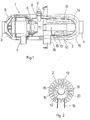
- the heater shown as an example corresponds to that from DE-OS 21 39 504. This is a heater for heating the interior of a motor vehicle with warm air.
- the fuel is supplied via the spark plug connector 8, in which the ignition device 9 is also used.
- the prepared, ignitable mixture is ignited in the lateral prechamber 10 and burns in the combustion chamber 11, which is followed by a flame tube 12.
- This flame tube 12 projects into the heat exchanger 13, which has indirect heating surfaces (fins) 14 on its outside and indirect heating surfaces (fins) 15 on its inside.
- the exhaust gas is discharged through the exhaust pipe 16.
- the fresh air sucked in through the fresh air inlet connection 3 flows through the heating device 1 and is heated with the indirect heating surfaces 15 when flowing through the annular space between the housing 2 and the heat exchanger 13 and leaves the heating device 1 as heating air via the heating air outlet connection 4.
- the heating of the fresh air is carried out by the hot ones Combustion gases emerging from the flame tube 12, which is open at the end, and deflected on the wall of the heat exchanger 13 and flowing through the annular space 17 between the flame tube 12 and the heat exchanger 13 with the inner indirect heating surfaces 14.
- a baffle 18 is arranged in the flow path of the exhaust gas in front of the exhaust pipe 16 in the annular space 17 between the flame tube 12 and the heat exchanger 13.
- This baffle plate 18 covers at least a region of the lower half of the annular space, preferably half of the annular space 17, so that the exhaust gas is forced to flow through the entire annular space 17 and to a certain extent flow away from the annular space half via the exhaust gas connector 16.
- the guide plate 17 can be fastened to the heat exchanger 13 via a fastening leg 18, the inner indirect heating surfaces (ribs) 14 of which are of course shortened in this area.
- the guide plate 17 can also be fastened directly to the ribs 14 without a fastening leg 18. Installation is very simple since the guide plate 17 is only inserted into the heat exchanger 13 and then fastened.
- the baffle 17 can also have exhaust gas passage openings 20 in order to enable a part of the exhaust gas to flow directly to the exhaust port 16. In this way, an optimization of the exhaust gas temperature reduction can be achieved in a simple manner by extending the residence time of the exhaust gas for heat transfer.
Landscapes
- Engineering & Computer Science (AREA)
- Physics & Mathematics (AREA)
- Thermal Sciences (AREA)
- Chemical & Material Sciences (AREA)
- Combustion & Propulsion (AREA)
- Mechanical Engineering (AREA)
- General Engineering & Computer Science (AREA)
- Air-Conditioning For Vehicles (AREA)
- Central Heating Systems (AREA)
Applications Claiming Priority (2)
| Application Number | Priority Date | Filing Date | Title |
|---|---|---|---|
| DE3808061 | 1988-03-11 | ||
| DE3808061A DE3808061A1 (de) | 1988-03-11 | 1988-03-11 | Anordnung zur absenkung der abgastemperatur bei heizeinrichtungen |
Publications (3)
| Publication Number | Publication Date |
|---|---|
| EP0331969A2 true EP0331969A2 (fr) | 1989-09-13 |
| EP0331969A3 EP0331969A3 (en) | 1990-10-24 |
| EP0331969B1 EP0331969B1 (fr) | 1991-10-23 |
Family
ID=6349435
Family Applications (1)
| Application Number | Title | Priority Date | Filing Date |
|---|---|---|---|
| EP89102983A Expired - Lifetime EP0331969B1 (fr) | 1988-03-11 | 1989-02-21 | Arrangement pour abaisser la température du gaz brûlé des installations du chauffage |
Country Status (4)
| Country | Link |
|---|---|
| EP (1) | EP0331969B1 (fr) |
| CA (1) | CA1336260C (fr) |
| DE (2) | DE3808061A1 (fr) |
| ES (1) | ES2027049T3 (fr) |
Cited By (3)
| Publication number | Priority date | Publication date | Assignee | Title |
|---|---|---|---|---|
| US9995505B2 (en) | 2014-12-22 | 2018-06-12 | Mcs Italy, S.P.A. | Transportable air heater |
| CN108534135A (zh) * | 2018-06-08 | 2018-09-14 | 中山劲牛科技有限公司 | 封堵头 |
| CN108534135B (zh) * | 2018-06-08 | 2024-06-04 | 中山劲牛科技有限公司 | 封堵头 |
Families Citing this family (4)
| Publication number | Priority date | Publication date | Assignee | Title |
|---|---|---|---|---|
| DE4116692A1 (de) * | 1991-05-22 | 1992-11-26 | Kreis Truma Geraetebau | Waermetauschereinsatz fuer luftheizgeraete |
| DE4208611C2 (de) * | 1992-03-18 | 1995-05-18 | Ruhrgas Ag | Atmosphärischer Gasbrenner mit einem schachtförmigen, einen Luftstrom führenden Gehäuse |
| DE4327139A1 (de) * | 1993-08-12 | 1995-02-16 | Eberspaecher J | Verfahren zur Verringerung der Geruchs- und Schadstoffemissionen bei Heizgeräten für Fahrzeuge und Anordnung zur Durchführung des Verfahrens |
| DE19516688C1 (de) * | 1995-05-06 | 1996-09-05 | Webasto Thermosysteme Gmbh | Fahrzeugheizgerät mit einem Abgasstutzen und einem Prallblech |
Citations (2)
| Publication number | Priority date | Publication date | Assignee | Title |
|---|---|---|---|---|
| FR2149772A5 (fr) * | 1971-08-06 | 1973-03-30 | Eberspaecher J | |
| DE3546368A1 (de) * | 1985-12-31 | 1987-07-02 | Siegfried Dipl Ing Weishaupt | Heizkessel |
Family Cites Families (1)
| Publication number | Priority date | Publication date | Assignee | Title |
|---|---|---|---|---|
| DE7147049U (de) * | 1972-04-20 | K Raunser Waermetechn Anlagen- Und Zentralheizungsbau | Ölofen |
-
1988
- 1988-03-11 DE DE3808061A patent/DE3808061A1/de active Granted
-
1989
- 1989-02-21 ES ES198989102983T patent/ES2027049T3/es not_active Expired - Lifetime
- 1989-02-21 DE DE8989102983T patent/DE58900389D1/de not_active Expired - Lifetime
- 1989-02-21 EP EP89102983A patent/EP0331969B1/fr not_active Expired - Lifetime
- 1989-02-28 CA CA000592322A patent/CA1336260C/fr not_active Expired - Fee Related
Patent Citations (2)
| Publication number | Priority date | Publication date | Assignee | Title |
|---|---|---|---|---|
| FR2149772A5 (fr) * | 1971-08-06 | 1973-03-30 | Eberspaecher J | |
| DE3546368A1 (de) * | 1985-12-31 | 1987-07-02 | Siegfried Dipl Ing Weishaupt | Heizkessel |
Cited By (3)
| Publication number | Priority date | Publication date | Assignee | Title |
|---|---|---|---|---|
| US9995505B2 (en) | 2014-12-22 | 2018-06-12 | Mcs Italy, S.P.A. | Transportable air heater |
| CN108534135A (zh) * | 2018-06-08 | 2018-09-14 | 中山劲牛科技有限公司 | 封堵头 |
| CN108534135B (zh) * | 2018-06-08 | 2024-06-04 | 中山劲牛科技有限公司 | 封堵头 |
Also Published As
| Publication number | Publication date |
|---|---|
| DE3808061C2 (fr) | 1990-07-19 |
| EP0331969B1 (fr) | 1991-10-23 |
| ES2027049T3 (es) | 1992-05-16 |
| EP0331969A3 (en) | 1990-10-24 |
| DE58900389D1 (de) | 1991-11-28 |
| CA1336260C (fr) | 1995-07-11 |
| DE3808061A1 (de) | 1989-09-21 |
Similar Documents
| Publication | Publication Date | Title |
|---|---|---|
| DE3722093A1 (de) | Brenner | |
| EP0307538A2 (fr) | Foyer de chaudière | |
| DE4328790C2 (de) | Brenner eines Fahrzeugheizgeräts | |
| DE2625615A1 (de) | Gasheizung | |
| DE3343617C2 (fr) | ||
| DE2432850C2 (de) | Heizgerät für Fahrzeuge | |
| DE3808061C2 (fr) | ||
| DE3628293A1 (de) | Heizkessel fuer die verbrennung fluessiger und/oder gasfoermiger brennstoffe | |
| EP0626539A2 (fr) | Radiateur à infrarouge aux fins de chauffage | |
| EP0128463B1 (fr) | Appareil de chauffage des locaux pour des locaux de petite dimension | |
| DE3049095C2 (de) | Heizvorrichtung zum Vorwärmen der Verbrennungsluft einer Brennkraftmaschine | |
| DE3410716A1 (de) | Brennkammer fuer heizeinrichtungen | |
| DE2337517A1 (de) | Gasbeheizter wassererhitzer | |
| DE2453202C3 (de) | Fahrzeug-Heizgerät | |
| DE19718898C1 (de) | Gasbrenner mit einem porösen Brennkörper | |
| AT234958B (de) | Warmluftheizung | |
| DE4218754A1 (de) | Verfahren zur schadstoffarmen Verbrennung | |
| DE3040720C2 (de) | Heizvorrichtung zum Vorwärmen der Verbrennungsluft einer Brennkraftmaschine | |
| DE2549490C2 (de) | Vorrichtung zum Vorwärmen der Luft in der Ansaugleitung einer Brennkraftmaschine | |
| DE7806382U1 (de) | Brennkopf fuer brennanlagen | |
| DE7919481U1 (de) | Anordnung von zuendelektroden bei heizoelbrennern | |
| EP0007424A1 (fr) | Brûleur pour combustion de carburants liquides | |
| EP0617244A2 (fr) | Réchauffeur d'air | |
| AT232169B (de) | Elektrische Glühdrahtzündvorrichtung für mit flüssigem Brennstoff betriebene Zerstäuberbrenner | |
| WO1993005342A1 (fr) | Bruleur a gaz, notamment pour gaz liquefie |
Legal Events
| Date | Code | Title | Description |
|---|---|---|---|
| PUAI | Public reference made under article 153(3) epc to a published international application that has entered the european phase |
Free format text: ORIGINAL CODE: 0009012 |
|
| AK | Designated contracting states |
Kind code of ref document: A2 Designated state(s): DE ES FR GB IT SE |
|
| PUAL | Search report despatched |
Free format text: ORIGINAL CODE: 0009013 |
|
| AK | Designated contracting states |
Kind code of ref document: A3 Designated state(s): DE ES FR GB IT SE |
|
| 17P | Request for examination filed |
Effective date: 19901114 |
|
| 17Q | First examination report despatched |
Effective date: 19910225 |
|
| GRAA | (expected) grant |
Free format text: ORIGINAL CODE: 0009210 |
|
| AK | Designated contracting states |
Kind code of ref document: B1 Designated state(s): DE ES FR GB IT SE |
|
| ITF | It: translation for a ep patent filed |
Owner name: BARZANO' E ZANARDO MILANO S.P.A. |
|
| ET | Fr: translation filed | ||
| GBT | Gb: translation of ep patent filed (gb section 77(6)(a)/1977) | ||
| REF | Corresponds to: |
Ref document number: 58900389 Country of ref document: DE Date of ref document: 19911128 |
|
| REG | Reference to a national code |
Ref country code: ES Ref legal event code: FG2A Ref document number: 2027049 Country of ref document: ES Kind code of ref document: T3 |
|
| PLBE | No opposition filed within time limit |
Free format text: ORIGINAL CODE: 0009261 |
|
| STAA | Information on the status of an ep patent application or granted ep patent |
Free format text: STATUS: NO OPPOSITION FILED WITHIN TIME LIMIT |
|
| 26N | No opposition filed | ||
| PGFP | Annual fee paid to national office [announced via postgrant information from national office to epo] |
Ref country code: DE Payment date: 19930120 Year of fee payment: 5 |
|
| PG25 | Lapsed in a contracting state [announced via postgrant information from national office to epo] |
Ref country code: DE Effective date: 19941101 |
|
| EAL | Se: european patent in force in sweden |
Ref document number: 89102983.7 |
|
| PGFP | Annual fee paid to national office [announced via postgrant information from national office to epo] |
Ref country code: FR Payment date: 19951222 Year of fee payment: 8 |
|
| PGFP | Annual fee paid to national office [announced via postgrant information from national office to epo] |
Ref country code: SE Payment date: 19960118 Year of fee payment: 8 |
|
| PGFP | Annual fee paid to national office [announced via postgrant information from national office to epo] |
Ref country code: ES Payment date: 19960209 Year of fee payment: 8 |
|
| PGFP | Annual fee paid to national office [announced via postgrant information from national office to epo] |
Ref country code: GB Payment date: 19960212 Year of fee payment: 8 |
|
| PG25 | Lapsed in a contracting state [announced via postgrant information from national office to epo] |
Ref country code: GB Effective date: 19970221 |
|
| PG25 | Lapsed in a contracting state [announced via postgrant information from national office to epo] |
Ref country code: SE Effective date: 19970222 Ref country code: ES Free format text: LAPSE BECAUSE OF NON-PAYMENT OF DUE FEES Effective date: 19970222 |
|
| GBPC | Gb: european patent ceased through non-payment of renewal fee |
Effective date: 19970221 |
|
| PG25 | Lapsed in a contracting state [announced via postgrant information from national office to epo] |
Ref country code: FR Effective date: 19971030 |
|
| EUG | Se: european patent has lapsed |
Ref document number: 89102983.7 |
|
| REG | Reference to a national code |
Ref country code: FR Ref legal event code: ST |
|
| REG | Reference to a national code |
Ref country code: ES Ref legal event code: FD2A Effective date: 19990405 |
|
| PG25 | Lapsed in a contracting state [announced via postgrant information from national office to epo] |
Ref country code: IT Free format text: LAPSE BECAUSE OF NON-PAYMENT OF DUE FEES;WARNING: LAPSES OF ITALIAN PATENTS WITH EFFECTIVE DATE BEFORE 2007 MAY HAVE OCCURRED AT ANY TIME BEFORE 2007. THE CORRECT EFFECTIVE DATE MAY BE DIFFERENT FROM THE ONE RECORDED. Effective date: 20050221 |