EP0331969A2 - Arrangement for lowering of flue gas temperature of heating installations - Google Patents
Arrangement for lowering of flue gas temperature of heating installations Download PDFInfo
- Publication number
- EP0331969A2 EP0331969A2 EP89102983A EP89102983A EP0331969A2 EP 0331969 A2 EP0331969 A2 EP 0331969A2 EP 89102983 A EP89102983 A EP 89102983A EP 89102983 A EP89102983 A EP 89102983A EP 0331969 A2 EP0331969 A2 EP 0331969A2
- Authority
- EP
- European Patent Office
- Prior art keywords
- heat exchanger
- exhaust gas
- guide plate
- annular space
- flame tube
- Prior art date
- Legal status (The legal status is an assumption and is not a legal conclusion. Google has not performed a legal analysis and makes no representation as to the accuracy of the status listed.)
- Granted
Links
Images
Classifications
-
- F—MECHANICAL ENGINEERING; LIGHTING; HEATING; WEAPONS; BLASTING
- F24—HEATING; RANGES; VENTILATING
- F24H—FLUID HEATERS, e.g. WATER OR AIR HEATERS, HAVING HEAT-GENERATING MEANS, e.g. HEAT PUMPS, IN GENERAL
- F24H9/00—Details
- F24H9/0052—Details for air heaters
- F24H9/0057—Guiding means
- F24H9/0068—Guiding means in combustion gas channels
-
- F—MECHANICAL ENGINEERING; LIGHTING; HEATING; WEAPONS; BLASTING
- F24—HEATING; RANGES; VENTILATING
- F24H—FLUID HEATERS, e.g. WATER OR AIR HEATERS, HAVING HEAT-GENERATING MEANS, e.g. HEAT PUMPS, IN GENERAL
- F24H3/00—Air heaters
- F24H3/02—Air heaters with forced circulation
- F24H3/06—Air heaters with forced circulation the air being kept separate from the heating medium, e.g. using forced circulation of air over radiators
- F24H3/065—Air heaters with forced circulation the air being kept separate from the heating medium, e.g. using forced circulation of air over radiators using fluid fuel
-
- F—MECHANICAL ENGINEERING; LIGHTING; HEATING; WEAPONS; BLASTING
- F24—HEATING; RANGES; VENTILATING
- F24H—FLUID HEATERS, e.g. WATER OR AIR HEATERS, HAVING HEAT-GENERATING MEANS, e.g. HEAT PUMPS, IN GENERAL
- F24H9/00—Details
- F24H9/0005—Details for water heaters
- F24H9/001—Guiding means
- F24H9/0026—Guiding means in combustion gas channels
Definitions
- the invention relates to an arrangement for lowering the exhaust gas temperature in heating devices with a combustion chamber, a combustion air blower, an electrical ignition device and a flame tube and a heat exchanger concentrically spaced around it with indirect heating surfaces (fins) and a nozzle for removing the combustion gases.
- Such heaters are known for use in mobile units such as motor vehicles, ships or caravans and are used there to heat the vehicle interior.
- the known heaters are operated with liquid fuel, preferably the fuel used, which is also used for combustion in the vehicle's engine.
- the interior can either be heated using warm air that is blown directly into the room or indirectly using heated water. With the so-called water heaters, it is also possible to preheat the engine circuit.
- Such a heater is described in detail in our DE-OS 21 39 504.
- a heating device is described which is provided with a die-cast piece, which forms in one piece the combustion chamber together with the heat exchanger provided on both sides with indirect heating surfaces (fins) and the exhaust gas connection, with a flame tube connected to the combustion chamber, which is provided in the fins Extends heat exchanger room.
- This device is designed for heating fresh air and is used to heat the vehicle interior.
- this heater has disadvantages with regard to exhaust gas routing.
- the combustion gas emerging from the flame tube and redirected on the heat exchanger wall flows as exhaust gas to the exhaust gas connection via the shortest route, and only a smaller proportion also flows through the annular space between the flame tube and heat exchanger along the ribs in the area opposite the exhaust gas connector .
- the invention has for its object to provide an arrangement in a generic heating device in which a more uniform temperature distribution in the heat exchanger and thereby a reduction in the exhaust gas temperature and an increase in the efficiency of the heat exchanger is achieved.
- This object is achieved according to the present invention in a generic heating device in that a baffle is arranged in the annular space between the flame tube and the heat exchanger in the flow path of the exhaust gas in front of the exhaust pipe in the area in which the exhaust pipe is molded onto the heat exchanger.
- a baffle is arranged in the annular space between the flame tube and the heat exchanger in the flow path of the exhaust gas in front of the exhaust pipe in the area in which the exhaust pipe is molded onto the heat exchanger.
- the baffle is arranged on the heat exchanger.
- the baffle has an angle with which it is inserted into the heat exchanger and firmly connected to it.
- the baffle in which the ribs of the heat exchanger are guided up to the baffle, the baffle can also be attached directly to the ribs of the heat exchanger.
- the baffle is a simple sheet metal part.
- Another expedient embodiment is characterized in that the guide plate has one or more gas passage openings.
- the guide plate can also be attached to the flame tube.
- the flame tube together with the baffle plate is placed on the combustion chamber when assembling the heater.
- the heater shown as an example corresponds to that from DE-OS 21 39 504. This is a heater for heating the interior of a motor vehicle with warm air.
- the fuel is supplied via the spark plug connector 8, in which the ignition device 9 is also used.
- the prepared, ignitable mixture is ignited in the lateral prechamber 10 and burns in the combustion chamber 11, which is followed by a flame tube 12.
- This flame tube 12 projects into the heat exchanger 13, which has indirect heating surfaces (fins) 14 on its outside and indirect heating surfaces (fins) 15 on its inside.
- the exhaust gas is discharged through the exhaust pipe 16.
- the fresh air sucked in through the fresh air inlet connection 3 flows through the heating device 1 and is heated with the indirect heating surfaces 15 when flowing through the annular space between the housing 2 and the heat exchanger 13 and leaves the heating device 1 as heating air via the heating air outlet connection 4.
- the heating of the fresh air is carried out by the hot ones Combustion gases emerging from the flame tube 12, which is open at the end, and deflected on the wall of the heat exchanger 13 and flowing through the annular space 17 between the flame tube 12 and the heat exchanger 13 with the inner indirect heating surfaces 14.
- a baffle 18 is arranged in the flow path of the exhaust gas in front of the exhaust pipe 16 in the annular space 17 between the flame tube 12 and the heat exchanger 13.
- This baffle plate 18 covers at least a region of the lower half of the annular space, preferably half of the annular space 17, so that the exhaust gas is forced to flow through the entire annular space 17 and to a certain extent flow away from the annular space half via the exhaust gas connector 16.
- the guide plate 17 can be fastened to the heat exchanger 13 via a fastening leg 18, the inner indirect heating surfaces (ribs) 14 of which are of course shortened in this area.
- the guide plate 17 can also be fastened directly to the ribs 14 without a fastening leg 18. Installation is very simple since the guide plate 17 is only inserted into the heat exchanger 13 and then fastened.
- the baffle 17 can also have exhaust gas passage openings 20 in order to enable a part of the exhaust gas to flow directly to the exhaust port 16. In this way, an optimization of the exhaust gas temperature reduction can be achieved in a simple manner by extending the residence time of the exhaust gas for heat transfer.
Abstract
Description
Die Erfindung betrifft eine Anordnung zur Absenkung der Abgastemperatur bei Heizeinrichtungen mit einer Brennkammer, einem Verbrennungsluftgebläse, einer elektrischen Zündeinrichtung sowie einem Flammrohr und einem dieses im Abstand konzentrisch umgebenden mit indirekten Heizflächen (Rippen) versehenen Wärmetauscher und einem Stutzen zur Abführung der Verbrennungsgase. Derartige Heizgeräte sind bekannt für die Verwendung in mobilen Einheiten wie Kraftfahrzeuge, Schiffe oder Wohnwagen und dienen dort zur Beheizung des Fahrzeuginnenraumes. Die bekannten Heizgeräte werden mit flüssigem Brennstoff betrieben, wobei vorzugsweise der Brennstoff Anwendung findet, der auch zur Verbrennung im fahrzeugeigenen Motor dient. Die Beheizung des Innenraumes kann entweder über Warmluft erfolgen, die unmittelbar in den Raum eingeblasen wird oder indirekt über aufgeheiztes Wasser. Bei den sogenannten Wasserheizgeräten ist es zudem noch möglich, den Motorkreislauf vorzuheizen.The invention relates to an arrangement for lowering the exhaust gas temperature in heating devices with a combustion chamber, a combustion air blower, an electrical ignition device and a flame tube and a heat exchanger concentrically spaced around it with indirect heating surfaces (fins) and a nozzle for removing the combustion gases. Such heaters are known for use in mobile units such as motor vehicles, ships or caravans and are used there to heat the vehicle interior. The known heaters are operated with liquid fuel, preferably the fuel used, which is also used for combustion in the vehicle's engine. The interior can either be heated using warm air that is blown directly into the room or indirectly using heated water. With the so-called water heaters, it is also possible to preheat the engine circuit.
Ein derartiges Heizgerät ist ausführlich in unserer DE-OS 21 39 504 beschrieben. In dieser Druckschrift wird eine Heizeinrichtung beschrieben, die mit einem Druckgußstück versehen ist, welches einstückig die Brennkammer mitsamt den beidseitig mit indirekten Heizflächen (Rippen) versehenen Wärmetauscher und den Abgasstutzen bildet, wobei an die Brennkammer ein Flammrohr angeschlossen ist, das in den mit Rippen versehenen Wärmetauscherraum hineinragt. Dieses Gerät ist für die Aufheizung von Frischluft ausgelegt und dient zur Beheizung des Fahrzeuginnenraumes.Such a heater is described in detail in our DE-OS 21 39 504. In this document, a heating device is described which is provided with a die-cast piece, which forms in one piece the combustion chamber together with the heat exchanger provided on both sides with indirect heating surfaces (fins) and the exhaust gas connection, with a flame tube connected to the combustion chamber, which is provided in the fins Extends heat exchanger room. This device is designed for heating fresh air and is used to heat the vehicle interior.
Dieses Heizgerät weist jedoch bezüglich der Abgasführung Nachteile auf. Bei der dort geschützten Anordnung strömt das aus dem Flammrohr austretende und an der Wärmetauscherwand umge lenkte Verbrennungsgas als Abgas auf dem Kürzesten Weg dem Abgasstutzen zu, und nur ein geringerer Anteil durchströmt auch den Ringraum zwischen Flammrohr und Wärmetauscher entlang den Rippen in dem dem Abgasstutzen gegenüberliegenden Bereich. Dadurch ergibt sich eine Ungleichmäßigkeit in der Temperaturverteilung und infolge des relativ geringen Strömungsweges des Abgases eine unnötig hohe Abgastemperatur am Abgasaustritt.However, this heater has disadvantages with regard to exhaust gas routing. In the arrangement protected there, the combustion gas emerging from the flame tube and redirected on the heat exchanger wall flows as exhaust gas to the exhaust gas connection via the shortest route, and only a smaller proportion also flows through the annular space between the flame tube and heat exchanger along the ribs in the area opposite the exhaust gas connector . This results in an unevenness in the temperature distribution and, due to the relatively small flow path of the exhaust gas, leads to an unnecessarily high exhaust gas temperature at the exhaust gas outlet.
Der Erfindung liegt die Aufgabe zugrunde, eine Anordnung bei einer gattungsgemäßen Heizeinrichtung aufzuzeigen, bei welcher eine gleichmäßigere Temperaturverteilung im Wärmetauscher und dadurch eine Absenkung der Abgastemperatur und eine Erhöhung des Wirkungsgrades des Wärmetauschers erreicht wird.The invention has for its object to provide an arrangement in a generic heating device in which a more uniform temperature distribution in the heat exchanger and thereby a reduction in the exhaust gas temperature and an increase in the efficiency of the heat exchanger is achieved.
Diese Aufgabe wird gemäß der vorliegenden Erfindung bei einer gattungsgemäßen Heizeinrichtung dadurch gelöst, daß im Strömungsweg des Abgases vor dem Abgasstutzen in dem Bereich, in dem der Abgasstutzen an den Wärmetauscher angeformt ist, in dem Ringraum zwischen Flammrohr und Wärmetauscher ein Leitblech angeordnet ist. Hierdurch wird mit einfachen Mitteln erreicht, daä das Abgas nicht mehr auf dem kürzesten Weg dem Abgasstutzen zugeführt wird, sondern daß es gezwungen wird, den gesamten Ringraum zwischen Flammrohr und Wärmetauscher entlang der eingezogenen indirekten Heizflächen (Rippen) zu durchströmen. Das hat wiederum den Vorteil, daß eine gleichmäßigere Temperaturverteilung erreicht wird und infolge der längeren Verweilzeit des Abgases eine Absenkung der Abgastemperatur am Austrittsstutzen erreicht wird. Bezüglich der Größe des Leitbleches had es sich als zweckmäßig erwiesen, daß dieses Leitblech einen Bereich zwischen 45° und 180° des Ringraumes abdeckt. Bevorzugt wird hierbei ein Bereich von 120° bis 180°. Es hat sich gezeigt, daß mit dieser Dimensionierung eine Optimierung der Verweilzeit des Abgases erreicht wird. Gemäß einer zweckmäßigen Weiterführung der Erfindung ist das Leitblech an den Wärmetauscher angeordnet. Hierzu weist das Leitblech einen Winkel auf, mit dem es in den Wärmetauscher eingeschoben und mit diesem fest verbunden wird. Bei einer zweckmäßigen Ausgestaltung, bei der die Rippen des Wärmetauschers bis an das Leitblech geführt sind, kann das Leitblech auch unmittelbar an den Rippen des Wärmetauschers befestigt werden. In diesem Fall ist das Leitblech ein einfaches Blechteil. Eine Weitere zweckmäßige Ausgestaltung ist dadurch gekennzeichnet, daß das Leitblech ein oder mehrere Gasdurchtrittsöffnungen aufweist.This object is achieved according to the present invention in a generic heating device in that a baffle is arranged in the annular space between the flame tube and the heat exchanger in the flow path of the exhaust gas in front of the exhaust pipe in the area in which the exhaust pipe is molded onto the heat exchanger. In this way it is achieved with simple means that the exhaust gas is no longer the shortest Path is fed to the exhaust pipe, but that it is forced to flow through the entire annular space between the flame tube and heat exchanger along the retracted indirect heating surfaces (fins). This in turn has the advantage that a more uniform temperature distribution is achieved and, due to the longer residence time of the exhaust gas, the exhaust gas temperature is reduced at the outlet connection. With regard to the size of the guide plate, it had proven to be expedient for this guide plate to cover an area between 45 ° and 180 ° of the annular space. A range of 120 ° to 180 ° is preferred. It has been shown that this dimensioning optimizes the residence time of the exhaust gas. According to an expedient development of the invention, the baffle is arranged on the heat exchanger. For this purpose, the baffle has an angle with which it is inserted into the heat exchanger and firmly connected to it. In an expedient embodiment, in which the ribs of the heat exchanger are guided up to the baffle, the baffle can also be attached directly to the ribs of the heat exchanger. In this case, the baffle is a simple sheet metal part. Another expedient embodiment is characterized in that the guide plate has one or more gas passage openings.
Ein Ausführungsbeispiel der Erfindung ist vereinfacht und schematisch in den Figuren dargestellt. Dabei zeigt:
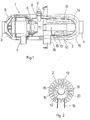
- Fig. 1 einen Schnitt durch ein Heizgerät
- Fig. 2 einen Schnitt an der angegebenen Stelle II-II.
- Fig. 1 shows a section through a heater
- Fig. 2 shows a section at the specified point II-II.
Schließlich kann nach einer weiteren Ausgestaltung das Leitblech auch an dem Flammrohr befestigt sein. In diesem Fall wird beim Zusammenbau des Heizgerätes das Flammrohr samt Leitblech auf die Brennkammer aufgesetzt.Finally, according to a further embodiment, the guide plate can also be attached to the flame tube. In this case, the flame tube together with the baffle plate is placed on the combustion chamber when assembling the heater.
Das als Beispiel dargestellte Heizgerät entspricht dem aus der DE-Os 21 39 504. Dabei handelt es sich um ein Heizgerät für die Beheizung des Innenraumes eines Kraftfahrzeuges mit Warmluft.The heater shown as an example corresponds to that from DE-OS 21 39 504. This is a heater for heating the interior of a motor vehicle with warm air.
Bei der Heizeinrichtung 1 ist in einem metallischen Gehäuse 2, das einen axialen Frischlufteintrittsstutzen 3 und einen ebenfalls axialen Heizluftaustrittsstutzen 4 aufweist, ein Frischluftansauggebläse 5 und auf gleicher Welle ein Verbrennungsluftgebläse 6, das die Verbrennungsluft über den Verbrennungsluftansaugstutzen 7 ansaugt, angeordnet. Die Brennstoffzufuhr erfolgt über den Zündkerzenstutzen 8, in dem auch die Zündeinrichtung 9 eingesetzt ist. Das aufbereitete, zündfähige Gemisch wird in der seitlichen Vorkammer 10 gezündet und verbrennt in der Brenkkammer 11, an die sich ein Flammrohr 12 anschließt. Dieses Flammrohr 12 ragt in den Wärmetauscher 13, der an seiner Außenseite indirekte Heizflächen (Rippen) 14 und an seiner Innenseite indirekte Heizflächen (Rippen) 15 aufweist. Das Abgas wird über den Abgasstutzen 16 abgeführt. Die durch den Frischlufteintrittsstutzen 3 angesaugte Frischluft durchströmt die Heizeinrichtung 1 und wird beim Durchströmen des Ringraumes zwischen Gehäuse 2 und dem Wärmetauscher 13 mit den indirekten Heizflächen 15 aufgeheizt und verläßt als Heizluft die Heizeinrichtung 1 über den Heizluftaustrittsstutzen 4. Die Aufheizung der Frischluft erfolgt durch die heißen Verbrennungsgase, die aus dem Flammrohr 12, das stirnseitig offen ist, austreten und an der Wand des Wärmetauscher 13 umgelenkt werden und den Ringraum 17 zwischen Flammrohr 12 und Wärmetauscher 13 mit den inneren indirekten Heizflächen 14 durchströmt.In the
Bei der bekannten Einrichtung nimmt das Verbrennungsgas den Kürzesten und widerstandslosesten Weg vom Flammrohraustritt zum Abgasstutzen 16, wodurch sowohl eine gleichmäßige Strömung im Wärmetauscher 13 verhindert wird als auch eine längere Verweilzeit zur Wärmeübertragung auf die Frischluft. Gemäß der vorliegenden Erfindung ist daher in dem Ringraum 17 zwischen Flammrohr 12 und Wärmetauscher 13 ein Leitblech 18 im Strömungsweg des Abgases vor dem Abgasstutzen 16 angeordnet. Dieses Leitblech 18 deckt mindestens einen Bereich der unteren Ringraumhälfte ab, vorzugsweise den halben Ringraum 17, so daß das Abgas gezwungen ist, den gesamten Ringraum 17 zu durchströmen und gewissermaßen von der Ringraumhälfte über dem Abgasstutzen 16 abzuströmen. Das Leitblech 17 kann über einen Befestigungsschenkel 18 an dem Wärmetauscher 13 befestigt sein, dessen innere indirekten Heizflächen (Rippen) 14 in diesem Bereich natürlich verkürzt sind. Das Leitblech 17 kann auch - ohne Befestigungsschenkel 18 - direkt an den Rippen 14 befestigt sein. Die Montage ist sehr einfach, da das Leitblech 17 in den Wärmetauscher 13 nur eingeschoben und dann befestigt wird. Das Leitblech 17 kann auch Abgasdurchtrittsöffnungen 20 aufweisen, um einen Teil des Abgases eine direkte Zuströmung zum Abgasstutzen 16 zu ermöglichen. Hierdurch kann in einfacher Weise eine Optimierung der Abgastemperaturabsenkung durch Verlängerung der Verweilzeit des Abgases zur Wärmeübertragung erreicht werden.In the known device, the combustion gas takes the shortest and most resistant path from the flame tube outlet to the
Claims (6)
Applications Claiming Priority (2)
| Application Number | Priority Date | Filing Date | Title |
|---|---|---|---|
| DE3808061A DE3808061A1 (en) | 1988-03-11 | 1988-03-11 | ARRANGEMENT FOR REDUCING EXHAUST GAS TEMPERATURE IN HEATING DEVICES |
| DE3808061 | 1988-03-11 |
Publications (3)
| Publication Number | Publication Date |
|---|---|
| EP0331969A2 true EP0331969A2 (en) | 1989-09-13 |
| EP0331969A3 EP0331969A3 (en) | 1990-10-24 |
| EP0331969B1 EP0331969B1 (en) | 1991-10-23 |
Family
ID=6349435
Family Applications (1)
| Application Number | Title | Priority Date | Filing Date |
|---|---|---|---|
| EP89102983A Expired - Lifetime EP0331969B1 (en) | 1988-03-11 | 1989-02-21 | Arrangement for lowering of flue gas temperature of heating installations |
Country Status (4)
| Country | Link |
|---|---|
| EP (1) | EP0331969B1 (en) |
| CA (1) | CA1336260C (en) |
| DE (2) | DE3808061A1 (en) |
| ES (1) | ES2027049T3 (en) |
Cited By (1)
| Publication number | Priority date | Publication date | Assignee | Title |
|---|---|---|---|---|
| US9995505B2 (en) | 2014-12-22 | 2018-06-12 | Mcs Italy, S.P.A. | Transportable air heater |
Families Citing this family (4)
| Publication number | Priority date | Publication date | Assignee | Title |
|---|---|---|---|---|
| DE4116692A1 (en) * | 1991-05-22 | 1992-11-26 | Kreis Truma Geraetebau | HEAT EXCHANGER INSERT FOR AIR HEATERS |
| DE4208611C2 (en) * | 1992-03-18 | 1995-05-18 | Ruhrgas Ag | Atmospheric gas burner with a shaft-shaped housing that guides an air flow |
| DE4327139A1 (en) * | 1993-08-12 | 1995-02-16 | Eberspaecher J | Process for reducing odor and pollutant emissions from heating devices for vehicles and arrangement for carrying out the process |
| DE19516688C1 (en) * | 1995-05-06 | 1996-09-05 | Webasto Thermosysteme Gmbh | Heating unit for vehicles, with outlet deflection sheet |
Citations (2)
| Publication number | Priority date | Publication date | Assignee | Title |
|---|---|---|---|---|
| FR2149772A5 (en) * | 1971-08-06 | 1973-03-30 | Eberspaecher J | |
| DE3546368A1 (en) * | 1985-12-31 | 1987-07-02 | Siegfried Dipl Ing Weishaupt | Heating boiler |
Family Cites Families (1)
| Publication number | Priority date | Publication date | Assignee | Title |
|---|---|---|---|---|
| DE7147049U (en) * | 1972-04-20 | K Raunser Waermetechn Anlagen- Und Zentralheizungsbau | Oil stove |
-
1988
- 1988-03-11 DE DE3808061A patent/DE3808061A1/en active Granted
-
1989
- 1989-02-21 ES ES198989102983T patent/ES2027049T3/en not_active Expired - Lifetime
- 1989-02-21 EP EP89102983A patent/EP0331969B1/en not_active Expired - Lifetime
- 1989-02-21 DE DE8989102983T patent/DE58900389D1/en not_active Expired - Lifetime
- 1989-02-28 CA CA000592322A patent/CA1336260C/en not_active Expired - Fee Related
Patent Citations (2)
| Publication number | Priority date | Publication date | Assignee | Title |
|---|---|---|---|---|
| FR2149772A5 (en) * | 1971-08-06 | 1973-03-30 | Eberspaecher J | |
| DE3546368A1 (en) * | 1985-12-31 | 1987-07-02 | Siegfried Dipl Ing Weishaupt | Heating boiler |
Cited By (1)
| Publication number | Priority date | Publication date | Assignee | Title |
|---|---|---|---|---|
| US9995505B2 (en) | 2014-12-22 | 2018-06-12 | Mcs Italy, S.P.A. | Transportable air heater |
Also Published As
| Publication number | Publication date |
|---|---|
| EP0331969B1 (en) | 1991-10-23 |
| DE3808061A1 (en) | 1989-09-21 |
| ES2027049T3 (en) | 1992-05-16 |
| DE3808061C2 (en) | 1990-07-19 |
| EP0331969A3 (en) | 1990-10-24 |
| CA1336260C (en) | 1995-07-11 |
| DE58900389D1 (en) | 1991-11-28 |
Similar Documents
| Publication | Publication Date | Title |
|---|---|---|
| DE3722093A1 (en) | BURNER | |
| EP0307538A2 (en) | Furnace device | |
| DE4328790C2 (en) | Burner of a vehicle heater | |
| DE2625615A1 (en) | GAS HEATING | |
| DE3343617C2 (en) | ||
| DE2432850C2 (en) | Heater for vehicles | |
| DE3808061C2 (en) | ||
| DE3628293A1 (en) | Heating boiler for burning liquid and/or gaseous fuels | |
| EP0626539A2 (en) | Gas fueled infrared radiator for heating purposes | |
| EP0128463B1 (en) | Space heating apparatus for small spaces | |
| DE3049095C2 (en) | Heating device for preheating the combustion air of an internal combustion engine | |
| DE3410716A1 (en) | COMBUSTION CHAMBER FOR HEATING EQUIPMENT | |
| DE2337517A1 (en) | Gas fired water heater especially for heating systems - has an air blower and porous burner plate and heat exchanger | |
| DE2453202C3 (en) | Vehicle heater | |
| DE19718898C1 (en) | Gas burner with a porous burner | |
| AT234958B (en) | Warm air heating | |
| DE4218754A1 (en) | Method of providing low pollution combustion of gaseous or aerosol fuel - involves supplying fuel and combustion air to suction side of driven, bladed impeller | |
| DE3040720C2 (en) | Heating device for preheating the combustion air of an internal combustion engine | |
| DE2549490C2 (en) | Device for preheating the air in the intake line of an internal combustion engine | |
| DE7806382U1 (en) | COMBUSTION HEAD FOR COMBUSTION SYSTEMS | |
| DE7919481U1 (en) | ARRANGEMENT OF IGNITION ELECTRODES IN OIL BURNERS | |
| EP0007424A1 (en) | Burner device for combustion of liquid fuel | |
| EP0617244A2 (en) | Air heater | |
| AT232169B (en) | Electric glow wire ignition device for liquid fuel-operated atomizer burners | |
| WO1993005342A1 (en) | Gas burner, in particular for liquefied gas |
Legal Events
| Date | Code | Title | Description |
|---|---|---|---|
| PUAI | Public reference made under article 153(3) epc to a published international application that has entered the european phase |
Free format text: ORIGINAL CODE: 0009012 |
|
| AK | Designated contracting states |
Kind code of ref document: A2 Designated state(s): DE ES FR GB IT SE |
|
| PUAL | Search report despatched |
Free format text: ORIGINAL CODE: 0009013 |
|
| AK | Designated contracting states |
Kind code of ref document: A3 Designated state(s): DE ES FR GB IT SE |
|
| 17P | Request for examination filed |
Effective date: 19901114 |
|
| 17Q | First examination report despatched |
Effective date: 19910225 |
|
| GRAA | (expected) grant |
Free format text: ORIGINAL CODE: 0009210 |
|
| AK | Designated contracting states |
Kind code of ref document: B1 Designated state(s): DE ES FR GB IT SE |
|
| ITF | It: translation for a ep patent filed |
Owner name: BARZANO' E ZANARDO MILANO S.P.A. |
|
| ET | Fr: translation filed | ||
| GBT | Gb: translation of ep patent filed (gb section 77(6)(a)/1977) | ||
| REF | Corresponds to: |
Ref document number: 58900389 Country of ref document: DE Date of ref document: 19911128 |
|
| REG | Reference to a national code |
Ref country code: ES Ref legal event code: FG2A Ref document number: 2027049 Country of ref document: ES Kind code of ref document: T3 |
|
| PLBE | No opposition filed within time limit |
Free format text: ORIGINAL CODE: 0009261 |
|
| STAA | Information on the status of an ep patent application or granted ep patent |
Free format text: STATUS: NO OPPOSITION FILED WITHIN TIME LIMIT |
|
| 26N | No opposition filed | ||
| PGFP | Annual fee paid to national office [announced via postgrant information from national office to epo] |
Ref country code: DE Payment date: 19930120 Year of fee payment: 5 |
|
| PG25 | Lapsed in a contracting state [announced via postgrant information from national office to epo] |
Ref country code: DE Effective date: 19941101 |
|
| EAL | Se: european patent in force in sweden |
Ref document number: 89102983.7 |
|
| PGFP | Annual fee paid to national office [announced via postgrant information from national office to epo] |
Ref country code: FR Payment date: 19951222 Year of fee payment: 8 |
|
| PGFP | Annual fee paid to national office [announced via postgrant information from national office to epo] |
Ref country code: SE Payment date: 19960118 Year of fee payment: 8 |
|
| PGFP | Annual fee paid to national office [announced via postgrant information from national office to epo] |
Ref country code: ES Payment date: 19960209 Year of fee payment: 8 |
|
| PGFP | Annual fee paid to national office [announced via postgrant information from national office to epo] |
Ref country code: GB Payment date: 19960212 Year of fee payment: 8 |
|
| PG25 | Lapsed in a contracting state [announced via postgrant information from national office to epo] |
Ref country code: GB Effective date: 19970221 |
|
| PG25 | Lapsed in a contracting state [announced via postgrant information from national office to epo] |
Ref country code: SE Effective date: 19970222 Ref country code: ES Free format text: LAPSE BECAUSE OF NON-PAYMENT OF DUE FEES Effective date: 19970222 |
|
| GBPC | Gb: european patent ceased through non-payment of renewal fee |
Effective date: 19970221 |
|
| PG25 | Lapsed in a contracting state [announced via postgrant information from national office to epo] |
Ref country code: FR Effective date: 19971030 |
|
| EUG | Se: european patent has lapsed |
Ref document number: 89102983.7 |
|
| REG | Reference to a national code |
Ref country code: FR Ref legal event code: ST |
|
| REG | Reference to a national code |
Ref country code: ES Ref legal event code: FD2A Effective date: 19990405 |
|
| PG25 | Lapsed in a contracting state [announced via postgrant information from national office to epo] |
Ref country code: IT Free format text: LAPSE BECAUSE OF NON-PAYMENT OF DUE FEES;WARNING: LAPSES OF ITALIAN PATENTS WITH EFFECTIVE DATE BEFORE 2007 MAY HAVE OCCURRED AT ANY TIME BEFORE 2007. THE CORRECT EFFECTIVE DATE MAY BE DIFFERENT FROM THE ONE RECORDED. Effective date: 20050221 |