EP0303053A2 - Dispositif de transfert de feuilles - Google Patents
Dispositif de transfert de feuilles Download PDFInfo
- Publication number
- EP0303053A2 EP0303053A2 EP88110921A EP88110921A EP0303053A2 EP 0303053 A2 EP0303053 A2 EP 0303053A2 EP 88110921 A EP88110921 A EP 88110921A EP 88110921 A EP88110921 A EP 88110921A EP 0303053 A2 EP0303053 A2 EP 0303053A2
- Authority
- EP
- European Patent Office
- Prior art keywords
- sheet
- printing
- feed table
- cylinder
- printing unit
- Prior art date
- Legal status (The legal status is an assumption and is not a legal conclusion. Google has not performed a legal analysis and makes no representation as to the accuracy of the status listed.)
- Granted
Links
- 238000007639 printing Methods 0.000 claims abstract description 51
- 230000002093 peripheral effect Effects 0.000 claims abstract description 19
- 230000005540 biological transmission Effects 0.000 claims abstract description 11
- 230000001133 acceleration Effects 0.000 claims abstract description 6
- 230000001154 acute effect Effects 0.000 description 2
- 230000006835 compression Effects 0.000 description 2
- 238000007906 compression Methods 0.000 description 2
- 230000001934 delay Effects 0.000 description 2
- 238000007645 offset printing Methods 0.000 description 2
- 238000007664 blowing Methods 0.000 description 1
- 230000000694 effects Effects 0.000 description 1
- 238000007646 gravure printing Methods 0.000 description 1
Images


Classifications
-
- B—PERFORMING OPERATIONS; TRANSPORTING
- B65—CONVEYING; PACKING; STORING; HANDLING THIN OR FILAMENTARY MATERIAL
- B65H—HANDLING THIN OR FILAMENTARY MATERIAL, e.g. SHEETS, WEBS, CABLES
- B65H9/00—Registering, e.g. orientating, articles; Devices therefor
- B65H9/16—Inclined tape, roller, or like article-forwarding side registers
- B65H9/163—Tape
-
- B—PERFORMING OPERATIONS; TRANSPORTING
- B41—PRINTING; LINING MACHINES; TYPEWRITERS; STAMPS
- B41F—PRINTING MACHINES OR PRESSES
- B41F21/00—Devices for conveying sheets through printing apparatus or machines
- B41F21/04—Grippers
- B41F21/05—In-feed grippers
Definitions
- the invention relates to a device for transferring sheets to a printing unit of a sheet-fed rotary printing press having at least one plate cylinder and one impression cylinder.
- the invention has for its object to provide a device of this type which, with a simple structure with a few moving sheet conveying elements, can supply the printing unit with a large number of sheets per unit of time in register, thus enabling the printing press to be operated at very high speeds.
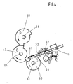
- the printing unit shown in FIG. 1, designated overall by 1, comprises a plate cylinder 2, a blanket cylinder 3 and a printing cylinder 4.
- the printing cylinder 4 has twice the diameter of the cylinders 2, 3 and carries two gripper systems 51, 52 an offset printing unit.
- the invention is not limited to use in offset printing units, but rather can also be used in any other type of printing unit, that is to say high-pressure or gravure printing units.
- the printing press further comprises a feed table 5, to which the sheets are fed individually in the known manner, not shown, in the direction of arrow a.
- a feed table 5 to which the sheets are fed individually in the known manner, not shown, in the direction of arrow a.
- several conveyor belts 6, 7, 8, 9 are provided, each of which runs over two deflection rollers 10, 11 and tensioning rollers 12, 13, at least one of the deflection rollers 10, 11 is driven, in such a way that the upper run of the conveyor belts runs in the direction of arrow b.
- the conveyor belts 6 to 9 thus run at an acute angle to the feed and conveying direction of the sheet, which is indicated by the arrow a.
- the deflection rollers 10, 11 are expediently fastened with the tensioning rollers 12, 13 to a carrier 14 which is rotatably mounted about an axis 15 by the acute angle between the conveying direction of the sheet, arrow a, and the transport direction of the conveyor belts 6 to 9, Arrow b to be able to adjust.
- a side mark 16, 17 is firmly attached on both sides.
- the conveyor belts 6 to 9 guide each sheet against the side mark 16 with a movement component directed transversely to the conveying direction a and thereby effect a side alignment of the sheet during its transport. Due to the rotatable arrangement of the carrier 14, there is also the possibility of guiding the sheet against the side mark 17 and aligning it laterally there.
- a movement component directed transversely to the conveying direction can also be given to the sheet in that in addition to conveyor belts or conveying rollers rotating in the conveying direction, air nozzles blowing obliquely thereto or an additional conveyor belt rotating obliquely or transversely thereto are provided.
- a conveyor roller 18 is arranged in the feed table, which extends over the entire width of the feed table 5, or individual conveyor rollers located next to one another are installed.
- a coil spring is wound around the axis 19 of the conveyor roller 18, one end of which is connected to a fixed part of the feed table 5, while the other end is fastened to the conveyor roller 18.
- the coil spring tends to rotate the conveyor roller 18 in the opposite direction of the arrow c.
- a disk 21 is attached, to which one end of a rope 22 is connected and on which part of the rope can be wound.
- the other end of the rope 22 is attached to a lever 23 which is pivotable about an axis 24.
- Each lever 23 carries a roller 25 which is held in contact with a control disk 28 by means of a compression spring 27 which is supported on a fixed circuit board 26 and engages with the other end on the lever 23.
- the two control disks 28 are firmly seated on a shaft 29 which is driven synchronously with the machine speed.
- this drive another drive which alternately accelerates and decelerates the conveyor roller can be used.
- a plurality of pivot levers 31 are fastened to a continuous axis 30, on the free end of which a pressure roller 32 is each freely rotatably mounted.
- the axis 30 is in turn controlled synchronously with the machine speed in such a way that the pressure rollers 32 are temporarily pressed against the conveyor roller 18 and are temporarily lifted from the latter.
- a pre-alignment front mark 33 is pivotably mounted on the feed table in a known manner, which consists of a plurality of stops which are distributed over the width of the feed table.
- An upper guide drum 34 with a gripper system 49 and a front mark 50 is arranged above the end of the feed table 5.
- the diameter of the upper guide drum 34 is smaller than the diameter of the plate cylinder 2, since the upper guide drum has a lower average peripheral speed than the plate cylinder 2 or the printing cylinder 4 rotating at the same peripheral speed due to the delay in the feeding speed of the sheets, but after every half a turn of the printing cylinder 4 or one revolution of the plate cylinder 2 and one revolution of the upper guide drum 34, the gripper system 49 of which must face one of the gripper systems 50, 51 for sheet transfer.
- the top guide drum can also be designed with two gripper systems. Then their diameter increases accordingly.
- the upper guide drum 34 is firmly seated on a shaft 35, on which a pinion 36 is also placed.
- the pinion 36 meshes with a gear 37, which is placed together with a support plate 38 on a shaft 39 parallel to the shaft 35.
- the support disk 38 carries four driver rollers 40 to 43.
- the driver rollers interact in pairs with the two side flanks of a raised spatial control cam 46.
- the parts 38 to 46 form a non-uniformly translating gear, which is the transfer drum 34 continuously accelerated from a low peripheral speed to a high peripheral speed, briefly remained at this high peripheral speed, then decelerated and then briefly remained at the low peripheral speed.
- the control cam 46 is placed on a main drive shaft 47 of the printing press.
- the main drive shaft 47 also carries a bevel gear 48 per printing unit, by means of which the cylinders 2 to 4 are driven in a manner known per se, not shown, via downstream gear wheels.
- the ropes 22 therefore begin to unwind from the disks 21 and accelerate the conveyor roller 18 in the direction of arrow c.
- the control shaft 30 pivots the lever 31 and thereby brings the pressure roller 32 to bear on the sheet.
- the control disks 28 are now mounted so eccentrically that they deflect the levers 23 by increasing paths when the shaft 29 is rotated further and thus accelerate the conveyor roller 18 and consequently also the arc.
- the clamping of the sheet between the conveyor roller 18 and the pressure rollers 32 ensures that, regardless of its strength and ripple, its leading edge aligned with the pre-alignment mark 33 is moved to the transfer drum 34 without the risk of misalignment.
- the sheet reaches the end of the feed table 5 at a speed which is slightly higher than the peripheral speed of the transfer drum 34 at this moment, the sheet runs into the opened gripper system 49 and comes to rest against the front mark 50. The grippers then close of the gripper system 49. The sheet thus runs to the front mark 50 at a speed which is lower than the speed of the sheet during printing. A rebound of the perforation of the sheet can therefore be avoided despite a very high machine speed. Furthermore, even when it is removed from the feed table 5, there is no need to fear that it will entrain the following sheet.
- the transfer drum 34 is accelerated by means of the non-uniform transmission gear 38 to 46 until the peripheral speed of the transfer drum 34 is approximately equal to the peripheral speed of the printing cylinder 4.
- the non-uniformly geared transmission 38 to 46 is expediently designed such that the transfer drum 34 is still slightly accelerated when the sheet transfer begins. This ensures that a tooth flank change in the drive of the transfer drum 34, which disrupts the exact transfer of the sheet, is avoided.
- the grippers of the gripper system 49 of the transfer drum 34 now transfer the sheet to the grippers, for example of the gripper system 52 of the printing cylinder 4, which rotates at a constant high speed.
- the larger diameter of the printing cylinder 4 has the advantage that the path available for the sheet transfer from the gripper system 49 to the gripper system 51 or 52 is longer than when transferring to a printing cylinder of smaller diameter and only one gripper system. An even longer transfer path can be achieved if the transfer drum is also designed with two gripper systems on the circumference and a correspondingly larger diameter.
- the non-uniformly converting gear 38 to 46 delays the rotation of the transfer drum 34 until it in turn reaches a peripheral speed which is slightly below the speed at which the next sheet is fed from the feed table 5.
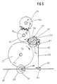
- the same feed table 5 with the conveying roller 18, the pressure rollers 32 and the pre-alignment front mark 33 can also be used, which is also provided in the first exemplary embodiment.
- a pressure cylinder 60 with a front mark 59 and a gripper system 61 which fixes the sheet to this mark.
- the pressure cylinder 60 seated on a shaft 62 interacts with a blanket cylinder 63 which sits on a shaft 64.
- the blanket cylinder 63 is in turn set against a plate cylinder 65 on a shaft 66.
- the cylinders 60, 63 and 65 are driven by a main drive shaft 67.
- a bevel gear 68 which meshes with a further bevel gear 69, is placed on this.
- a pinion 70 is fixedly connected to the bevel gear 69 and engages in a gear 71.
- the gear wheel 71 is seated on a shaft 72 on which a transport drum 73 is fixed.
- the transport drum 73 provided with grippers serves to remove the sheets from the printing cylinder 60.
- the gear 71 in turn meshes with a gear 74 which is loosely rotatably mounted on the shaft 62 of the printing cylinder 60.
- the gear 74 is in engagement with another wider gear 75, which is firmly placed on the shaft 64 of the blanket cylinder 63.
- the gear 75 is also in engagement with both a gear 76, which is firmly seated on the shaft 66 of the plate cylinder 65, and a gear 77, which is firmly attached to the shaft 62 and has no teeth in a region 78.
- a support plate 79 is also placed, which carries a driving roller 80.
- the driving roller 80 can interact with a spatial control cam 81 which is fixedly connected to a bevel gear 83 via a shaft 82.
- the bevel gear 83 meshes with a further bevel gear 84 placed on the main drive shaft 67.
- the control cam 81 of the non-uniformly geared transmission 79 to 81 is designed such that it entrains the driving roller 80 in a form-fitting manner when the area 78 of the gear 77 runs past the gear 75.
- the shape of the control curve 81 is further selected so that the support disk 79 is first decelerated in this area and then accelerated again until the support disk 79 and thus the gear 77 again have the same peripheral speed as the gear 75.
- the deceleration takes place up to a value at which the pressure cylinder 60 placed on the shaft 62 has a peripheral speed which is slightly below the feed speed of the sheet from the feed table 5.
- the grippers of the gripper system 61 close at the moment the sheet starts running at the front mark 59.
- the control curve 81 begins to accelerate the shaft 62 of the printing cylinder 60.
- the toothing of the gear 77 engages with the gear 75.
- the pressure cylinder 60 is driven via the gear 75.
- the roller 80 is not in engagement with the control cam 81 so that it does not impair the drive from the gear wheel 75.
- the sheet guided on the impression cylinder 60 is printed. This sheet is then removed in a known manner, not shown, via the transport drum 73.
- the beginning of the tooth-free area 78 of the gear 77 faces the gear 75 again, so that the gear 75 no longer drives the shaft 62 and thus the pressure cylinder 60.
- the driving roller 80 again reaches the area of the control cam 81, in which it is free of play is guided so that the pressure cylinder is driven via the control cam 81.
- the effective area now delays the printing cylinder 60 to a peripheral speed in which the next sheet can be taken over.
- the plate cylinder 65 and the blanket cylinder 63 are also driven at machine speed during the acceleration and deceleration of the impression cylinder via the gears 71, 74, 75 and 76.
- the average peripheral speed of the printing cylinder 60 is lower than the peripheral speed of the blanket cylinder 63 or the plate cylinder 65, both of which are the same size, the diameter of the printing cylinder is correspondingly smaller.
Landscapes
- Supply, Installation And Extraction Of Printed Sheets Or Plates (AREA)
- Registering Or Overturning Sheets (AREA)
- Inking, Control Or Cleaning Of Printing Machines (AREA)
- Sheets, Magazines, And Separation Thereof (AREA)
Applications Claiming Priority (2)
| Application Number | Priority Date | Filing Date | Title |
|---|---|---|---|
| DE3726780 | 1987-08-12 | ||
| DE19873726780 DE3726780A1 (de) | 1987-08-12 | 1987-08-12 | Vorrichtung zur uebergabe von bogen |
Publications (4)
| Publication Number | Publication Date |
|---|---|
| EP0303053A2 true EP0303053A2 (fr) | 1989-02-15 |
| EP0303053A3 EP0303053A3 (en) | 1990-04-04 |
| EP0303053B1 EP0303053B1 (fr) | 1992-09-09 |
| EP0303053B2 EP0303053B2 (fr) | 2000-10-25 |
Family
ID=6333561
Family Applications (1)
| Application Number | Title | Priority Date | Filing Date |
|---|---|---|---|
| EP88110921A Expired - Lifetime EP0303053B2 (fr) | 1987-08-12 | 1988-07-08 | Dispositif de transfert de feuilles |
Country Status (5)
| Country | Link |
|---|---|
| US (1) | US4825762A (fr) |
| EP (1) | EP0303053B2 (fr) |
| JP (1) | JP2752381B2 (fr) |
| CA (1) | CA1287255C (fr) |
| DE (2) | DE3726780A1 (fr) |
Cited By (5)
| Publication number | Priority date | Publication date | Assignee | Title |
|---|---|---|---|---|
| DE4431684A1 (de) * | 1994-09-06 | 1996-03-14 | Kba Planeta Ag | Vorrichtung zum Antreiben einer Bogenbeschleunigungseinrichtung |
| DE4431683A1 (de) * | 1994-09-06 | 1996-03-14 | Kba Planeta Ag | Antrieb einer Bogenbeschleunigungseinrichtung |
| DE4431682A1 (de) * | 1994-09-06 | 1996-03-14 | Kba Planeta Ag | Kurvengesteuertes Bogenbeschleunigungssystem |
| DE4431680A1 (de) * | 1994-09-06 | 1996-03-14 | Kba Planeta Ag | Kurvengesteuerter Antrieb eines Bogenbeschleunigungssystems |
| DE102004057842A1 (de) * | 2004-12-01 | 2006-06-08 | Koenig & Bauer Ag | Einrichtung zum Beeinflussen von Bogen |
Families Citing this family (12)
| Publication number | Priority date | Publication date | Assignee | Title |
|---|---|---|---|---|
| GB8619504D0 (en) * | 1986-08-11 | 1986-09-24 | Rockwell Graphic Systems Ltd | Accelerating drive member |
| DE4020730C2 (de) * | 1990-06-29 | 1999-04-15 | Krause Biagosch Gmbh | Verfahren und Vorrichtung zum Verbessern der Stapelqualität eines Bogenstapels |
| DE4435264C2 (de) * | 1994-10-01 | 2001-05-10 | Heidelberger Druckmasch Ag | Bogenniederhalter |
| US5584246A (en) * | 1995-06-09 | 1996-12-17 | Werner Kammann Maschinenfabrik Gmbh | Process and apparatus for printing on flat individual articles |
| DE19901699B4 (de) * | 1998-02-04 | 2007-11-15 | Heidelberger Druckmaschinen Ag | Verfahren und eine Vorrichtung zur Durchführung des Verfahrens zur Beseitigung von rhythmischen Passerfehlern in Rotationsdruckmaschinen |
| DE10020648A1 (de) * | 2000-04-27 | 2001-10-31 | Heidelberger Druckmasch Ag | Bogendruckmaschine |
| JP2002087635A (ja) * | 2000-09-12 | 2002-03-27 | Canon Inc | シート材搬送装置およびそれを備える記録装置、記録機構付き撮像装置 |
| DE102004019220A1 (de) * | 2004-04-21 | 2005-11-10 | Koenig & Bauer Ag | Vorrichtung zum Zuführen von Bogen |
| JP2006124175A (ja) * | 2004-10-14 | 2006-05-18 | Graphic Management Associates Inc | 加速装置及び減速装置を備えた製品フィーダ |
| JP5838128B2 (ja) * | 2012-05-31 | 2015-12-24 | 株式会社木田鉄工所 | 搬送装置 |
| CN103144424B (zh) * | 2013-03-07 | 2016-01-20 | 天津长荣印刷设备股份有限公司 | 一种电子套准系统及其工作方法 |
| WO2017099762A1 (fr) * | 2015-12-09 | 2017-06-15 | Hewlett-Packard Development Company, L.P. | Repérage de supports d'impression au moyen d'une pince d'extraction |
Family Cites Families (25)
| Publication number | Priority date | Publication date | Assignee | Title |
|---|---|---|---|---|
| US2335954A (en) * | 1938-09-16 | 1943-12-07 | Ditto Inc | Duplicating machine |
| US2687886A (en) * | 1950-10-21 | 1954-08-31 | Alphonse W Pitner | Registering apparatus for printing machines |
| US2708405A (en) * | 1951-08-17 | 1955-05-17 | Miller Printing Machinery Co | Printing press feed and registering mechanism |
| GB1187254A (en) * | 1967-09-26 | 1970-04-08 | Gestetner Ltd | Offset Printing Apparatus |
| US3858508A (en) * | 1969-09-15 | 1975-01-07 | Ricoh Kk | Offset printing machine |
| DE2062503A1 (de) * | 1970-12-18 | 1972-06-22 | Koenig & Bauer Schnellpressfab | Bogenzuführung bei Druckmaschinen |
| IT991860B (it) * | 1973-07-25 | 1975-08-30 | Nebiolo Spa | Macchina rotativa da stampa per fogli singoli |
| SE375511B (fr) * | 1973-08-13 | 1975-04-21 | Svecia Silkscreen Maskiner Ab | |
| DE2449629A1 (de) * | 1974-10-18 | 1976-04-29 | Maschf Augsburg Nuernberg Ag | Bogenanlegevorrichtung fuer rotationsdruckmaschinen |
| DE2452051A1 (de) * | 1974-11-02 | 1976-05-06 | Maschf Augsburg Nuernberg Ag | Vorrichtung zum passergerechten anlegen von bogen in bogenrotationsdruckmaschinen |
| US3954494A (en) * | 1974-12-30 | 1976-05-04 | Chevron Research Company | Wax-flux composition containing a succinimide salt of an alkylaryl sulfonic acid for soldering |
| DD126254A1 (fr) * | 1976-06-18 | 1977-07-06 | ||
| DE7713720U1 (de) * | 1977-04-30 | 1979-04-05 | Raes, Karl, 6201 Wildsachsen | Druckwerk einer bogendruckmaschine |
| DE2720675C2 (de) * | 1977-05-07 | 1982-09-02 | M.A.N. Maschinenfabrik Augsburg-Nürnberg AG, 8900 Augsburg | Bogenzufuhreinrichtung für eine Rotations-Druckmaschine |
| DE2744925C2 (de) * | 1977-10-06 | 1986-06-12 | Koenig & Bauer AG, 8700 Würzburg | Einrichtung auf einer Stopptrommel für eine Bogenrotationsdruckmaschine |
| DD142694A1 (de) * | 1979-04-02 | 1980-07-09 | Guenter Weisbach | Bogenrotationsdruckmaschine mit einem von unten arbeitenden vorgreifer |
| JPS57136744U (fr) * | 1981-02-20 | 1982-08-26 | ||
| DE3108808C2 (de) * | 1981-03-07 | 1985-02-21 | M.A.N.- Roland Druckmaschinen AG, 6050 Offenbach | Bogen-Rotations-Flachdruckmaschine |
| JPS57197164A (en) * | 1981-05-30 | 1982-12-03 | Komori Printing Mach Co Ltd | Monochromatic sheet-fed off-set press |
| JPS5862643U (ja) * | 1981-10-22 | 1983-04-27 | 三菱重工業株式会社 | 印刷機の給紙胴駆動装置 |
| DE3318117A1 (de) * | 1982-05-20 | 1983-11-24 | International Standard Electric Corp., 10022 New York, N.Y. | Blattausrichtvorrichtung |
| JPS58181536U (ja) * | 1982-05-31 | 1983-12-03 | リョービ株式会社 | 両面印刷機の給紙装置 |
| GB2166419B (en) * | 1984-09-28 | 1988-05-05 | Rotaprint Plc | Sheet registration device and method |
| DE3511897A1 (de) * | 1985-04-01 | 1986-10-09 | Mabeg Maschinenbau Gmbh Nachf. Hense & Pleines Gmbh & Co, 6050 Offenbach | Vorrichtung zum seitlichen ausrichten von bogen |
| DE8514775U1 (de) * | 1985-05-20 | 1985-06-27 | Heidelberger Druckmaschinen Ag, 6900 Heidelberg | Antrieb für einen Bogentransportmechanismus am Anleger einer Rotationsdruckmaschine |
-
1987
- 1987-08-12 DE DE19873726780 patent/DE3726780A1/de not_active Withdrawn
-
1988
- 1988-07-08 EP EP88110921A patent/EP0303053B2/fr not_active Expired - Lifetime
- 1988-07-08 DE DE8888110921T patent/DE3874459D1/de not_active Expired - Lifetime
- 1988-08-02 US US07/227,368 patent/US4825762A/en not_active Expired - Fee Related
- 1988-08-09 CA CA000574216A patent/CA1287255C/fr not_active Expired - Lifetime
- 1988-08-09 JP JP63197307A patent/JP2752381B2/ja not_active Expired - Fee Related
Non-Patent Citations (1)
| Title |
|---|
| None |
Cited By (9)
| Publication number | Priority date | Publication date | Assignee | Title |
|---|---|---|---|---|
| DE4431684A1 (de) * | 1994-09-06 | 1996-03-14 | Kba Planeta Ag | Vorrichtung zum Antreiben einer Bogenbeschleunigungseinrichtung |
| DE4431683A1 (de) * | 1994-09-06 | 1996-03-14 | Kba Planeta Ag | Antrieb einer Bogenbeschleunigungseinrichtung |
| DE4431682A1 (de) * | 1994-09-06 | 1996-03-14 | Kba Planeta Ag | Kurvengesteuertes Bogenbeschleunigungssystem |
| DE4431680A1 (de) * | 1994-09-06 | 1996-03-14 | Kba Planeta Ag | Kurvengesteuerter Antrieb eines Bogenbeschleunigungssystems |
| DE4431682C2 (de) * | 1994-09-06 | 1998-11-26 | Kba Planeta Ag | Kurvengesteuertes Bogenbeschleunigungssystem |
| DE4431683C2 (de) * | 1994-09-06 | 1998-11-26 | Kba Planeta Ag | Antrieb einer Bogenbeschleunigungseinrichtung |
| DE4431680C2 (de) * | 1994-09-06 | 1998-11-26 | Kba Planeta Ag | Antrieb eines Bogenbeschleunigungssystems |
| DE4431684C2 (de) * | 1994-09-06 | 1998-12-03 | Kba Planeta Ag | Vorrichtung zum Antreiben einer Bogenbeschleunigungseinrichtung |
| DE102004057842A1 (de) * | 2004-12-01 | 2006-06-08 | Koenig & Bauer Ag | Einrichtung zum Beeinflussen von Bogen |
Also Published As
| Publication number | Publication date |
|---|---|
| EP0303053A3 (en) | 1990-04-04 |
| EP0303053B1 (fr) | 1992-09-09 |
| JP2752381B2 (ja) | 1998-05-18 |
| EP0303053B2 (fr) | 2000-10-25 |
| DE3874459D1 (de) | 1992-10-15 |
| CA1287255C (fr) | 1991-08-06 |
| JPS6469344A (en) | 1989-03-15 |
| DE3726780A1 (de) | 1989-02-23 |
| US4825762A (en) | 1989-05-02 |
Similar Documents
| Publication | Publication Date | Title |
|---|---|---|
| EP0303053B1 (fr) | Dispositif de transfert de feuilles | |
| EP0244568B1 (fr) | Convoyeur de feuilles pour machines traitant des feuilles | |
| EP0059873B1 (fr) | Dispositif de prélèvement d'imprimés des disques de réception d'un appareil de pliage | |
| DE10014417A1 (de) | Vorrichtung zum Transport eines Bogens für eine Rotationsdruckmaschine | |
| DE3612067C2 (fr) | ||
| EP0498068A1 (fr) | Plieuse, dans laquelle le transport d'exemplaires pliés est realisé en passant par des moyens de transport, des galets partiels et des cordons | |
| DE2435665A1 (de) | Rotationsdruckmaschine | |
| DE10047395B4 (de) | Transportsystem für flache Produkte | |
| EP1479627B1 (fr) | Dispositif d'alignement de feuilles | |
| DE3230846C2 (de) | Vorrichtung zum Fördern von Bogen oder Bogenpaketen | |
| EP1209111A2 (fr) | Dispositif pour déposer des feuilles | |
| DE2407752A1 (de) | Verfahren und vorrichtung zum auslegen von bogen | |
| EP0405107A1 (fr) | Dispositif pour déliasser des feuilles de papier empilées | |
| DE1923625C3 (de) | Vorrichtung zur Zuführung von Bogen für eine Bogen-Rotationsdruckmaschine | |
| EP0241663B1 (fr) | Dispositif pour convoyer et tourner des feuilles pour machines traitant des feuilles | |
| DE3126103C2 (fr) | ||
| EP0014233B1 (fr) | Dispositif pour amener des feuilles à une imprimeuse | |
| EP0243700B1 (fr) | Dispositif de sécurité pour une rotative d'impression | |
| DE29913487U1 (de) | Ausleger einer Bogen ausgebenden Maschine | |
| DE2624170C3 (de) | Seitenausrichtvorrichtung | |
| DE3629080C2 (fr) | ||
| DE69708026T2 (de) | Mechanismus zum Öffnen und Schliessen von Greifern eines Bogentransportzylinders in einer Bogendruckmaschine | |
| DE3107807C2 (de) | Bogenbeschleunigungsvorrichtung | |
| DE3034767C2 (fr) | ||
| DE69300644T2 (de) | Vorrichtung zum Zuführen eines Trägers durch eine Druckvorrichtung und Siebdruckmaschine. |
Legal Events
| Date | Code | Title | Description |
|---|---|---|---|
| PUAI | Public reference made under article 153(3) epc to a published international application that has entered the european phase |
Free format text: ORIGINAL CODE: 0009012 |
|
| AK | Designated contracting states |
Kind code of ref document: A2 Designated state(s): CH DE FR GB IT LI NL SE |
|
| PUAL | Search report despatched |
Free format text: ORIGINAL CODE: 0009013 |
|
| AK | Designated contracting states |
Kind code of ref document: A3 Designated state(s): CH DE FR GB IT LI NL SE |
|
| 17P | Request for examination filed |
Effective date: 19900321 |
|
| 17Q | First examination report despatched |
Effective date: 19910903 |
|
| GRAA | (expected) grant |
Free format text: ORIGINAL CODE: 0009210 |
|
| AK | Designated contracting states |
Kind code of ref document: B1 Designated state(s): CH DE FR GB IT LI NL SE |
|
| ITF | It: translation for a ep patent filed | ||
| REF | Corresponds to: |
Ref document number: 3874459 Country of ref document: DE Date of ref document: 19921015 |
|
| ET | Fr: translation filed | ||
| GBT | Gb: translation of ep patent filed (gb section 77(6)(a)/1977) |
Effective date: 19921201 |
|
| PLBI | Opposition filed |
Free format text: ORIGINAL CODE: 0009260 |
|
| PLBI | Opposition filed |
Free format text: ORIGINAL CODE: 0009260 |
|
| 26 | Opposition filed |
Opponent name: KBA-PLANETA AG Effective date: 19930608 |
|
| 26 | Opposition filed |
Opponent name: KOENIG & BAUER AKTIENGESELLSCHAFT Effective date: 19930609 Opponent name: KBA-PLANETA AG Effective date: 19930608 |
|
| NLR1 | Nl: opposition has been filed with the epo |
Opponent name: KBA-PLANETA AG |
|
| EAL | Se: european patent in force in sweden |
Ref document number: 88110921.9 |
|
| PLAB | Opposition data, opponent's data or that of the opponent's representative modified |
Free format text: ORIGINAL CODE: 0009299OPPO |
|
| R26 | Opposition filed (corrected) |
Opponent name: KBA - PLANETA AG * 930609 KOENIG & BAUER AKTIENGES Effective date: 19930608 |
|
| PLAW | Interlocutory decision in opposition |
Free format text: ORIGINAL CODE: EPIDOS IDOP |
|
| APAE | Appeal reference modified |
Free format text: ORIGINAL CODE: EPIDOS REFNO |
|
| APAC | Appeal dossier modified |
Free format text: ORIGINAL CODE: EPIDOS NOAPO |
|
| APAC | Appeal dossier modified |
Free format text: ORIGINAL CODE: EPIDOS NOAPO |
|
| PLBQ | Unpublished change to opponent data |
Free format text: ORIGINAL CODE: EPIDOS OPPO |
|
| PLAB | Opposition data, opponent's data or that of the opponent's representative modified |
Free format text: ORIGINAL CODE: 0009299OPPO |
|
| R26 | Opposition filed (corrected) |
Opponent name: KOENIG & BAUER AKTIENGESELLSCHAFT * 19930609 KOENI Effective date: 19930608 |
|
| APAC | Appeal dossier modified |
Free format text: ORIGINAL CODE: EPIDOS NOAPO |
|
| NLR1 | Nl: opposition has been filed with the epo |
Opponent name: KOENIG & BAUER AKTIENGESELLSCHAFT |
|
| PLBQ | Unpublished change to opponent data |
Free format text: ORIGINAL CODE: EPIDOS OPPO |
|
| PLAW | Interlocutory decision in opposition |
Free format text: ORIGINAL CODE: EPIDOS IDOP |
|
| PLAB | Opposition data, opponent's data or that of the opponent's representative modified |
Free format text: ORIGINAL CODE: 0009299OPPO |
|
| R26 | Opposition filed (corrected) |
Opponent name: KOENIG & BAUER AKTIENGESELLSCHAFT * 19930609 KOENI Effective date: 19930608 |
|
| PUAH | Patent maintained in amended form |
Free format text: ORIGINAL CODE: 0009272 |
|
| STAA | Information on the status of an ep patent application or granted ep patent |
Free format text: STATUS: PATENT MAINTAINED AS AMENDED |
|
| NLR1 | Nl: opposition has been filed with the epo |
Opponent name: KOENIG & BAUER AKTIENGESELLSCHAFT |
|
| ITF | It: translation for a ep patent filed | ||
| 27A | Patent maintained in amended form |
Effective date: 20001025 |
|
| AK | Designated contracting states |
Kind code of ref document: B2 Designated state(s): CH DE FR GB IT LI NL SE |
|
| REG | Reference to a national code |
Ref country code: CH Ref legal event code: AEN Free format text: AUFRECHTERHALTUNG DES PATENTES IN GEAENDERTER FORM |
|
| NLR2 | Nl: decision of opposition | ||
| ET3 | Fr: translation filed ** decision concerning opposition | ||
| GBTA | Gb: translation of amended ep patent filed (gb section 77(6)(b)/1977) | ||
| NLR3 | Nl: receipt of modified translations in the netherlands language after an opposition procedure | ||
| REG | Reference to a national code |
Ref country code: GB Ref legal event code: IF02 |
|
| PGFP | Annual fee paid to national office [announced via postgrant information from national office to epo] |
Ref country code: CH Payment date: 20020619 Year of fee payment: 15 |
|
| PGFP | Annual fee paid to national office [announced via postgrant information from national office to epo] |
Ref country code: SE Payment date: 20020625 Year of fee payment: 15 Ref country code: NL Payment date: 20020625 Year of fee payment: 15 |
|
| PGFP | Annual fee paid to national office [announced via postgrant information from national office to epo] |
Ref country code: GB Payment date: 20020628 Year of fee payment: 15 |
|
| PGFP | Annual fee paid to national office [announced via postgrant information from national office to epo] |
Ref country code: FR Payment date: 20020711 Year of fee payment: 15 Ref country code: DE Payment date: 20020711 Year of fee payment: 15 |
|
| PG25 | Lapsed in a contracting state [announced via postgrant information from national office to epo] |
Ref country code: GB Free format text: LAPSE BECAUSE OF NON-PAYMENT OF DUE FEES Effective date: 20030708 |
|
| PG25 | Lapsed in a contracting state [announced via postgrant information from national office to epo] |
Ref country code: SE Free format text: LAPSE BECAUSE OF NON-PAYMENT OF DUE FEES Effective date: 20030709 |
|
| PG25 | Lapsed in a contracting state [announced via postgrant information from national office to epo] |
Ref country code: LI Free format text: LAPSE BECAUSE OF NON-PAYMENT OF DUE FEES Effective date: 20030731 Ref country code: CH Free format text: LAPSE BECAUSE OF NON-PAYMENT OF DUE FEES Effective date: 20030731 |
|
| PG25 | Lapsed in a contracting state [announced via postgrant information from national office to epo] |
Ref country code: NL Free format text: LAPSE BECAUSE OF NON-PAYMENT OF DUE FEES Effective date: 20040201 |
|
| PG25 | Lapsed in a contracting state [announced via postgrant information from national office to epo] |
Ref country code: DE Free format text: LAPSE BECAUSE OF NON-PAYMENT OF DUE FEES Effective date: 20040203 |
|
| GBPC | Gb: european patent ceased through non-payment of renewal fee |
Effective date: 20030708 |
|
| EUG | Se: european patent has lapsed | ||
| REG | Reference to a national code |
Ref country code: CH Ref legal event code: PL |
|
| PG25 | Lapsed in a contracting state [announced via postgrant information from national office to epo] |
Ref country code: FR Free format text: LAPSE BECAUSE OF NON-PAYMENT OF DUE FEES Effective date: 20040331 |
|
| NLV4 | Nl: lapsed or anulled due to non-payment of the annual fee |
Effective date: 20040201 |
|
| REG | Reference to a national code |
Ref country code: FR Ref legal event code: ST |
|
| PG25 | Lapsed in a contracting state [announced via postgrant information from national office to epo] |
Ref country code: IT Free format text: LAPSE BECAUSE OF NON-PAYMENT OF DUE FEES;WARNING: LAPSES OF ITALIAN PATENTS WITH EFFECTIVE DATE BEFORE 2007 MAY HAVE OCCURRED AT ANY TIME BEFORE 2007. THE CORRECT EFFECTIVE DATE MAY BE DIFFERENT FROM THE ONE RECORDED. Effective date: 20050708 |
|
| APAH | Appeal reference modified |
Free format text: ORIGINAL CODE: EPIDOSCREFNO |