EP0300115B1 - Verfahren und Vorrichtung zum maschinellen Ansetzen jeweils eines Zitzenbechers - Google Patents
Verfahren und Vorrichtung zum maschinellen Ansetzen jeweils eines Zitzenbechers Download PDFInfo
- Publication number
- EP0300115B1 EP0300115B1 EP88101053A EP88101053A EP0300115B1 EP 0300115 B1 EP0300115 B1 EP 0300115B1 EP 88101053 A EP88101053 A EP 88101053A EP 88101053 A EP88101053 A EP 88101053A EP 0300115 B1 EP0300115 B1 EP 0300115B1
- Authority
- EP
- European Patent Office
- Prior art keywords
- teat
- guide
- cow
- udder
- milked
- Prior art date
- Legal status (The legal status is an assumption and is not a legal conclusion. Google has not performed a legal analysis and makes no representation as to the accuracy of the status listed.)
- Expired - Lifetime
Links
- 238000000034 method Methods 0.000 title claims description 16
- 210000002445 nipple Anatomy 0.000 claims description 138
- 210000000481 breast Anatomy 0.000 claims description 34
- 230000033001 locomotion Effects 0.000 claims description 14
- 239000008267 milk Substances 0.000 claims description 14
- 210000004080 milk Anatomy 0.000 claims description 14
- 235000013336 milk Nutrition 0.000 claims description 14
- 230000008878 coupling Effects 0.000 claims description 8
- 238000010168 coupling process Methods 0.000 claims description 8
- 238000005859 coupling reaction Methods 0.000 claims description 8
- 238000006073 displacement reaction Methods 0.000 claims description 6
- 241001465754 Metazoa Species 0.000 claims description 4
- 238000011010 flushing procedure Methods 0.000 claims description 4
- 230000003287 optical effect Effects 0.000 claims description 3
- 238000002604 ultrasonography Methods 0.000 claims description 2
- 239000003599 detergent Substances 0.000 description 3
- 230000000694 effects Effects 0.000 description 2
- 239000007788 liquid Substances 0.000 description 2
- 210000001364 upper extremity Anatomy 0.000 description 2
- 206010038743 Restlessness Diseases 0.000 description 1
- 230000002411 adverse Effects 0.000 description 1
- 229910052782 aluminium Inorganic materials 0.000 description 1
- XAGFODPZIPBFFR-UHFFFAOYSA-N aluminium Chemical compound [Al] XAGFODPZIPBFFR-UHFFFAOYSA-N 0.000 description 1
- 230000005540 biological transmission Effects 0.000 description 1
- 239000003795 chemical substances by application Substances 0.000 description 1
- 230000006735 deficit Effects 0.000 description 1
- 238000001514 detection method Methods 0.000 description 1
- 229910052751 metal Inorganic materials 0.000 description 1
- 239000002184 metal Substances 0.000 description 1
- 238000009304 pastoral farming Methods 0.000 description 1
- 230000002787 reinforcement Effects 0.000 description 1
- 238000005406 washing Methods 0.000 description 1
Images


Classifications
-
- A—HUMAN NECESSITIES
- A01—AGRICULTURE; FORESTRY; ANIMAL HUSBANDRY; HUNTING; TRAPPING; FISHING
- A01K—ANIMAL HUSBANDRY; AVICULTURE; APICULTURE; PISCICULTURE; FISHING; REARING OR BREEDING ANIMALS, NOT OTHERWISE PROVIDED FOR; NEW BREEDS OF ANIMALS
- A01K1/00—Housing animals; Equipment therefor
- A01K1/12—Milking stations
-
- A—HUMAN NECESSITIES
- A01—AGRICULTURE; FORESTRY; ANIMAL HUSBANDRY; HUNTING; TRAPPING; FISHING
- A01J—MANUFACTURE OF DAIRY PRODUCTS
- A01J5/00—Milking machines or devices
- A01J5/017—Automatic attaching or detaching of clusters
- A01J5/0175—Attaching of clusters
Definitions
- the invention relates to a method for mechanically attaching a teat cup to a teat to be milked, the position of which is located by a sensor and compared with a position assumed by a teat attachment, which is changed in the direction of the teat until the teat attachment Has pushed the teat cup over the teat.
- This method has become known from FR-A-2 408 300 and uses an attachment device which serves to guide a teat cup under a cow and then automatically attach the teat cup to a teat.
- the attachment device has a U-shaped support which is formed by three arms and is mounted on a pin. Means are provided for rotating the pin and for moving the support up and down. Two arms can be pulled out as linear guides. At the end of the arm there is an electronic camera, which should locate the position of the teat to be milked as a sensor and a holder for holding the teat cup.
- the attachment device picks up a teat cup at a fixed point and carries out a pivoting movement, as a result of which the teat cup is guided under the cow's body and generally backwards to below the udder.
- the position of the teat is then determined by means of the electronic camera in connection with the electronic control, whereupon the control triggers the movement of the attachment device and changes it until the attachment device has pushed the teat cup over the end of the teat.
- the U-shaped support that can be swiveled in the horizontal plane has a number of disadvantages, which essentially result from the fact that the lever arm can very often suffer damage in a relatively rough barn operation, especially in large livestock farming. This also applies in particular to the drive elements of the guides, which must also be pivoted into the area of the cow in this document.
- the carrier or swivel arm becomes relatively heavy, which has a disadvantageous effect on the swivel bearing that bears the entire weight. With an appropriate constitution of the cow, when pivoting the attachment device, it must be expected that parts of the attachment device graze the cow, which can have an adverse effect on the milking result.
- the object of the present invention is therefore to improve the method of the type mentioned in the introduction in such a way that an exact guidance of each teat cup up to the teats is made possible.
- attachment device is spatially displaced by means of linear guides which can each be moved in mutually perpendicular directions, the attachment device being arranged on a guide extending transversely to the longitudinal direction of a cow, by the end of which the guide device is moved under the cow to be milked .
- any location below a cow to be milked can be reached by the attachment device, on the other hand, this only protrudes under the cow with a guide, so that the risk that this relatively narrow guide is sensitive to the cow touches is very low.
- all drive elements of the guides outside the area of the cow can remain, which practically eliminates the risk of damage by the cow.
- the respective displacements of the attachment device in the immediate vicinity of the teat to be milked in each case can be carried out relatively quickly.
- the guidance system can be designed so that it extends along several milking parlors which are arranged in a row one behind the other. In this way, a large number of animals can be milked at a relatively low cost.
- This device has considerable disadvantages.
- the carrier carrying the attachment device has to be pivoted with its drive elements for horizontal guidance under the cow.
- sensitive parts of the cow must therefore be touched by the attachment device, so that the cow becomes restless. Locating the teats to be milked is therefore largely impossible. Due to the high mechanical load on the swivel joint, this is also extremely susceptible to failure.
- a further object of the present invention is therefore to improve the device of the type mentioned above in that it enables simple and inexpensive means to precisely guide a teat cup to be attached to a teat.
- This object is achieved in that three axes are arranged as spatial linear components, each at right angles and displaceable relative to one another, one of which is designed as a movable guide, at the end of which the attachment device for moving transversely to the longitudinal axis of a cow is fastened in the immediate vicinity of its teat to be milked is.
- Such a linear axis system with guides which can be moved relative to one another permits very precise control of the teat cup in the area of the teat to be milked.
- the teat cup can be pushed under the cow in the shortest possible way without any significant impairment of the cow and gently and with even movements over the teat.
- the individual linear components can be made mechanically robust, and all sensitive drive elements can be arranged outside the sphere of influence of the cow, so that the attachment device is also protected from damage by the cow.
- the individual guides can be stored very precisely against each other in relatively simple displacement bearings. In this way, the attachment device can be gently adapted to the animal.
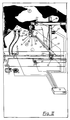
- the method according to the invention can expediently be carried out in a milking parlor (1) on which a cow (2) stands for the purpose of milking, whose udders (3) have teats (5, 6, 7,) oriented towards a stable floor (4). 8).
- the teats (5, 6) are adjacent to the rear legs (9, 10) of the cow (2), while the teats (7, 8) face the front legs of the cow (2). They protrude from a front part (13) of the udder (3).
- a guide system (15) is built up along a long side (14) of the milking parlor (1) in the vertical direction above the barn floor (4).
- This guide system (15) essentially consists of guides (16, 17, 18) which can be designed as metal profiles, for example aluminum profiles.
- the individual guides (16, 17, 18) run essentially at right angles to one another.
- the guide (16) extends essentially parallel to the longitudinal side (14) of the milking parlor (1), while the guide (17) extends perpendicularly to it and extends from the guide (16) in the direction extends to the udder (3).
- the guide (18) runs essentially perpendicular and is arranged perpendicular to the directions of the guides (16, 17).
- the individual guides (16, 17) are displaceably supported against one another in bearings (19, 20).
- bearings (19, 20) can be designed in such a way that in one guide (16, 17, 18) a flexible force transmitter is slidably mounted in the direction of the respective guide (16, 17, 18) on which the other Guide (18, 17, 16) is attached.
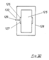
- a flexible power transmission is in particular a toothed belt (126) driven by a corresponding gear wheel (125), which carries a driver plate (126) to which the other guide (18, 17, 16) is attached.
- This toothed belt (126) is expediently mounted in the interior of the guide (16, 17, 18) designed as a box profile (128).
- the gear wheels (125) on which the toothed belt (126) is deflected are rotatably mounted within the box profile (128) at its respective ends.
- each of the guides (16, 17, 18) has at least one drive (21 22, 23), with the aid of which the guides (16, 17, 18) assigned to the drive relative to the guides (18, 18) 17, 16) can be moved. In this way, it is conceivable to move the guides (17, 18) along the longitudinal side (14) of the milking parlor (1) on the guide (16).
- the guide (17) can be displaced more or less far in relation to the guide (18) in the direction of the milking parlor (1).
- an end (24) of the guide (17) pointing in the direction of the cow (2) can create a space (25) on each floor above the barn floor (4) Brush a point that lies within the range of motion of the guides (16, 17, 18).
- the guide (17) is angled in an L-shape in the direction of the hind legs (9, 10) of the cow (2) through the web (26).
- This web (26) can be pivoted relative to the guide (17) connected to it.
- the web (26) carries on its web end (27) facing away from the end (24) the offset (28) which points essentially upwards in a vertical direction facing away from the barn floor (4).
- This offset (28) is provided on its upper end (29) facing away from the web (26) with the gripper (30), which has two gripper halves (31, 32) that can move towards one another.
- These two gripper halves (31, 32) enclose an interior (33) in which a teat cup (59) can be held by a corresponding movement of the gripper halves (31, 32).
- This teat cup (59) is placed on one of the teats (5, 6, 7, 8) with the aid of a control.
- This control is based on the sensors (49, 50) which are arranged in a frame (34).
- This frame (34) spans an interior (44) in which the sensors (49, 50) are aligned.
- the size of the interior (44) is designed such that two parallel legs (41, 42), which laterally delimit the frame (34), can be pushed over one of the teats (5, 6, 7, 8).
- the legs (41, 42) are connected to each other at one of their ends by a yoke (38). It forms a U-profile (43) with the legs (41, 42).
- Sensors (49, 50) oriented in the direction of the interior (44) are fastened in the legs (41, 42).
- the sensors (49) can be designed as infrared emitters, the beams of which are aimed at the sensors (5o), which can be designed as infrared-sensitive photo resistors.
- the sensors (49, 50) can be distributed within the legs (41, 42) in such a way that the sensors (49, 50) are arranged in a dense sequence (51) in a central part of the respective legs (41, 42). are distributed, while the sensors (49, 50) are arranged in a less dense distribution in the direction of the respectively opposite ends (52, 53) of the legs (41, 42).
- At least one additional sensor (54) is provided in the yoke (38), which sensor is oriented towards the interior Output (55) has.
- This sensor (54) can be designed as an ultrasound transmitter. This determines the distance to the teat (5,6,7,89 onto which the frame (34) is pushed. In addition, the sensor (54) centers the frame (34) with respect to the teat (5,6,7 ,8th).
- the frame (34) is fastened to the gripper (3o) via a coupling web (35), so that it has a fixed association with it.
- This assignment is dimensioned such that a teat cup (49) held by the gripper (3o) is arranged directly below the frame (34) with its upper end (9o) facing the teat (5,6,7,8). In this way, there is a fixed association between the frame (34) on the one hand and the upper end (91) on the other.
- the teat cup (49) gripped by the gripper (3o) can scan sensors (49,5o, 54) via the teat (5,6,7,8) into a position perpendicularly below the teat (5,6,7,8) extending plane controlled and then pushed by a vertical movement over the teat (5,6,7,8).
- the gripper (3o) and with it the frame (34) can be detached from the teat cup (59) so that the frame ( 34) other teat cups can be attached to the respective teats (7,8).
- the gripper (3o) and the frame (34) are released, any movements of the legs (41, 42) against one another can be avoided because of the U-shaped design of the frame (34).
- sensors can also be arranged in the frame (34), which are aligned in such a way that their rays meet at a common intersection.
- the gripper (3o) After the gripper (3o) has been released from the attached teat cup (59), it is available for attaching further teat cups (6o). If these have to be attached to the teats of another cow, the gripper (3o) is moved out of the area of the one cow (2) with the aid of the guide system (15) and is now available to move one to another milking parlor (66, 67) milking another cow (68,69).
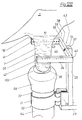
- a milking cluster (7,) which is connected to a milk container (72) via a milk line (71).
- a vacuum necessary for milking is generated by a vacuum pump (73), which acts via the milk line (71) in the individual teat cups (59, 60). With the help of this vacuum, the milk is withdrawn from the teats (5, 6, 7, 8) and transported into the milk container (72).
- a cycle necessary for milking between negative pressure on the one hand and atmospheric pressure on the other hand a pulse generator (74) is generated, which controls a desired milking cycle into the teat cups (59, 60) via a pulse line (75).
- the pulse generator (74) is connected on the one hand to the negative pressure generated by the vacuum pump (73) and on the other hand to atmospheric pressure.
- the vacuum pump (73) is usually driven by an electric motor (76).
- the individual guides (16, 17, 18) are moved towards the udder (3) so that the gripper (3o) in the longitudinal direction of the cow (2) from its front legs ( 11, 12) can be moved in the direction of the rear legs (9, 01).
- the signals (49, 50, 54) for controlling the movements required in each case, which are to be carried out by the guides (16, 17, 18), are emitted by the sensors.
- the negative pressure required for milking is introduced into the teat cup (59,6o).
- control of the guidance system (15) on the one hand and a milking machine (77) composed of the milk container (72), the vacuum pump (73) and the pulse generator (74) on the other hand are electrically connected to one another via a common control unit (78).
- a control pulse can be sent to the control unit (78), which in turn switches on the milking machine (77).
- the control unit (78) receives control impulses not only from the sensors (49, 50, 54) but also from a cow identifier (79), which the cow (2) wears, for example, on a collar (8o).
- This cow identifier (79) contains an assignment of the cow (2) identified by it to specific data in a data memory, for example its length, milk yield and feeding requirements.
- this data store can also contain data which refer to the anatomical nature of the udder (3) and the teat (5,6,7).
- the guidance system (15) based on the stored data in such a way that the milking cluster (7o) is controlled in the immediate vicinity of the udder (3) depending on the predetermined cow identification (79), so that only a fine adjustment is made due to the control pulses emitted by the sensors (49, 50, 54).
- the data stored in the control unit (78) can be checked with each individual milking process and adapted to the conditions found by the guidance system (15). For this purpose, the dimensions of the udder (3), the teats (5, 6, 7, 8) and the respective existing assignment are constantly corrected in the control unit (78) and adapted to the existing conditions.
- a mechanical reinforcement of the guide system (15) is possible in that at least some of the guides (16, 17, 18) are executed several times. For example, it is advisable to reinforce the guide (16) running in the longitudinal direction of the milking parlor (1) by a parallel guide (81) which is provided, for example, in the immediate vicinity of the barn floor (4).
- the guide (18) extending in the vertical direction can also be reinforced by a parallel guide (82) which is provided at a distance from the guide (16) so that it extends between the two guides (18, 82).
- fine control must be carried out with the aid of sensors (83, 84), which are located opposite each other Ends (85,86) of a driving carriage (87) are fixed and aligned towards a cow (2) standing between the ends (85,86).
- sensors can be attached directly to the working element (gripper 3o) or the L-shaped web (26).
- the entraining carriage (87) spans the cow standing on the milking parlor (1), the sensors (83, 84) protrude from brackets (88, 89) on both sides of the cow (2) in the direction of the barn floor (4), that the sensors (83, 84) can be aligned towards the udder (3).
- the guides (16, 17, 18) are controlled in accordance with the position of the udder (3) found by the sensors (83, 84) that a teat cup (91) gripped by the gripper (3o) can be placed directly on one of the teats (5,6,7,8).
- the gripper (3o) is controlled so that a teat cup (59,6o) is placed on each of the rear teats (5,6). Then additional teat cups (59.6o) are placed on the front teats (7.8). This prevents the milk lines (71) connected to the teat cups (59, 60) from twisting each other when the teat cups (59, 60) are attached.
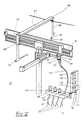
- the teat cups ( 91,92,93,94) is used in a holding device (95) in which a holder (96,97,98,99) is provided for each individual teat cup (91,92,93,94).
- the holder (96,97,98,99) can be designed in such a way that a bore extends through the holding device (95), the cross section of which corresponds approximately to an outer diameter of the teat cup (91,92,93,94).
- the teat cups (91,92,93,94) with their milk tubes (1oo) protrude into these holders (96,97,98,99) facing ends (1o1) and each lie with a collar (1o2) on the holding device (95). Between the collar (1o2) and an upper end (1o3) of the teat cup (91,92,93,94) facing the respective teat (5,6,7,8) there is an upper part of a teat cup wall surrounding the interior (65) ( 1o4), which can be gripped by the gripper (3o).
- the gripper (3o) After the gripper (3o) has gripped the teat cup (91,92,93,94) in the area of the upper part (1o4), it pulls it out of the holding device (95) and moves it towards the teats (5,6 , 7.8). He pulls the milk hose (100), which connects the teat cup (91,92,93,94) with a collecting piece, not shown, behind him, so that the milk hose (11o) extends through the holder (96,97.) , 98.99) extends. In addition, a cord (1o5) extends through these brackets (96,97,98,99), which connects the teat cup (91,92,93,94) with an automatic removal mechanism (not shown).
- This automatic take-off is controlled by the control unit (78) after the milking process has ended and then pulls the teat cup (91,92,93,94) from the milked teat (5,6,7,8) via the cord (1o5). Setting the holding device (95) as close as possible in the area of the cow (2) to be milked ensures that the cord (1o5) detaches the teat cup (91,92,93,94 from the teat (5,6,7,8) ) back into the holder provided for him (96,97,98,98).
- An automatic rinsing machine can be connected to the holder device (95) and is used to rinse the teat cups (91, 92, 93, 94) and the milk-draining system connected to them with the aid of a rinsing device.
- This washing machine is coupled to the individual teat cups (91, 92, 93, 94) with the aid of a coupling device (1o6) via a detergent line (1o7).
- This coupling device essentially consists from a flushing arm pivotally articulated on the holding device (92), in which semicircular recesses (1o7,1o8,1o9,11o) are provided for receiving the upper ends (1o3) of a teat cup (91,92,93,94).
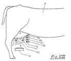
- the teats (5,6,7,8) can also be found using optical sensors.
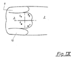
- a camera (112) or an optical system, which is connected to a camera (112) via corresponding lines, can be installed between the stable floor (4) and the udder (3).
- An attachment to the L-shaped web (26) is preferably possible in such a way that the optics are directed vertically upwards.
- an image of the udder (3) is generated in the camera (112) which corresponds to that of FIG. 9.
- the camera (112) is located centrally below the udder (3). This adjustment of the camera (112) is based on the teats (5,6,7,8), which is relatively easy to recognize because of its round shape.
- teat detection is further improved by the udder ((3) being directed by directed lighting (113) (see FIG. 1o) is steeled.
- shadows (114, 115, 116, 117) corresponding to the directional lighting (113) are formed on the four teats (5, 6, 7, 8). Based on this characteristic combination of shadows, the teats (5, 6, 7, 8) can be easily recognized by the camera (112).
- the teats (5, 6, 7, 8) can be assigned well both in their position to one another and with respect to the udder (3). Difficulties can only be determined by determining the height at which the teats (5, 6, 7, 8) are located above the barn floor (4). Two possibilities are conceivable for this purpose, both of which can be used.
- the lens or the camera (112) can be focused on a specific point on the teat (5, 6, 7, 8). The amount by which the lens of the camera (112) must be adjusted so that the teats (5,6,7,8) are sharply imaged is a measure of the distance that the teats (5,6,7,8 ) from the stable floor (4).
- the camera (112) it is also possible to focus the camera (112) to a predetermined height at a level provided below the udder (3). If the individual teat (5, 6, 7, 8) is not in focus during this focusing of the lens, the camera (112) is moved towards the udder (3) until the teat (5, 6 , 7,8) is brought about. The movement of the camera (112) necessary for the purpose of focusing is a further measure of the distance of the teats (5, 6, 7, 8) from the barn floor (4).
- the height of the teats (5, 6, 7, 8) relative to the stable floor (4) can be measured using a light bar (118).
- a plurality of spotlights (119, 122, 121, 122) are fastened to one another on this light bar (118) in the vertical direction.
- the beam path (123) emanating from this is covered by the teats (5, 6, 7, 8)
- conclusions can be drawn about the exact positioning of the udder (3) on the one hand and the teats (5,6,7,8) on the other hand.
- the light bar (118) can be mechanically connected to the carrier carriage (87).
- the light bar (118) is provided with a slot diaphragm (not shown).
- a correspondingly installed mirror system can also be used to recognize the respective position of the udder (3).
- the light bar (118) could be used as the light source for the mirrors. This solution has the advantage of keeping the camera (112) out of a mechanically endangered part.
- the position of the gripper (3o) is determined by incremental encoders. In addition, however, fine adjustment using pneumatic or hydraulic drives is also possible. From the of The signals (49, 50, 54, 83, 84, 112) and signals transmitted to the control unit (78) determine the positions of the teats (5, 6, 7, 8) and compare them with the position of the grippers (3o). Then the gripper (3o) moves to the determined position of the teats (5,6,7,8).
- a readjustment of the determined position is possible by loosening the grippers (3o) when the teat cups (59,6o) are in place and aligning them with the exact position of the teats (5,6,7,8). If this makes it necessary to correct the position of the teats (5, 6, 7, 8), this is adopted in the control unit (78) instead of the values previously stored in the control unit (78).
- the guide system (15) can be modified by installing a fine guide unit (124) running in the same direction on one or more guides (16, 17, 18). If, for example, it is slidably mounted on the guide (17) in its longitudinal direction, it can make fine adjustments with respect to the guide (17) and thereby the gripper (3o), which is attached to it, very precisely in the direction of the udder (3 ) proceed. Since the fine guide unit (124) has a relatively small mass compared to the guide (16, 17, 18) on which it is slidably mounted, a displacement of the fine guide unit (124) enables the gripper (3o) to be positioned very precisely .
Landscapes
- Life Sciences & Earth Sciences (AREA)
- Environmental Sciences (AREA)
- Animal Husbandry (AREA)
- Zoology (AREA)
- Biodiversity & Conservation Biology (AREA)
- Feeding And Watering For Cattle Raising And Animal Husbandry (AREA)
- Manipulator (AREA)
Applications Claiming Priority (2)
| Application Number | Priority Date | Filing Date | Title |
|---|---|---|---|
| DE19873702465 DE3702465A1 (de) | 1987-01-28 | 1987-01-28 | Verfahren und vorrichtung zum melken und ggfs. fuettern von freilaufenden, identifizierungsmittel tragenden kuehen |
| DE3702465 | 1987-01-28 |
Publications (2)
| Publication Number | Publication Date |
|---|---|
| EP0300115A1 EP0300115A1 (de) | 1989-01-25 |
| EP0300115B1 true EP0300115B1 (de) | 1994-04-06 |
Family
ID=6319691
Family Applications (1)
| Application Number | Title | Priority Date | Filing Date |
|---|---|---|---|
| EP88101053A Expired - Lifetime EP0300115B1 (de) | 1987-01-28 | 1988-01-26 | Verfahren und Vorrichtung zum maschinellen Ansetzen jeweils eines Zitzenbechers |
Country Status (2)
| Country | Link |
|---|---|
| EP (1) | EP0300115B1 (enExample) |
| DE (2) | DE3702465A1 (enExample) |
Cited By (14)
| Publication number | Priority date | Publication date | Assignee | Title |
|---|---|---|---|---|
| NL8900479A (nl) * | 1989-02-27 | 1990-09-17 | Lely Nv C Van Der | Melkinstallatie. |
| EP0472247A3 (en) * | 1988-09-21 | 1992-04-15 | C. Van Der Lely N.V. | An implement for automatically milking an animal |
| EP0519544A1 (en) * | 1991-06-10 | 1992-12-23 | C. van der Lely N.V. | An implement for milking animals |
| WO1993000001A1 (en) * | 1991-06-20 | 1993-01-07 | British Technology Group Ltd. | Automatic milking |
| US5272997A (en) * | 1989-02-27 | 1993-12-28 | C. Van Der Lely N.V. | Milking apparatus |
| US6055930A (en) * | 1995-10-27 | 2000-05-02 | Alfa Laval Agri Ab | Apparatus for moving an animal related means and a method therefor |
| EP1020111A1 (de) | 1999-01-14 | 2000-07-19 | Westfalia Landtechnik GmbH | Vorrichtung zum Ansetzen wenigstens eines Melkbechers an eine Zitze eines Tieres |
| WO2000076297A1 (de) | 1999-06-14 | 2000-12-21 | Westfalia Landtechnik Gmbh | Verfahren zum maschinellen melken von tieren, insbesondere von kühen |
| US6167839B1 (en) | 1996-08-22 | 2001-01-02 | Alfa Laval Agri Ab | Arrangement and a method of performing an animal-related action |
| US6269766B1 (en) | 1997-04-11 | 2001-08-07 | Alfa Laval Agri Ab | Teatcup magazine, a milking arrangement, and a method of handling a teatcup |
| US6357387B1 (en) | 1997-08-08 | 2002-03-19 | Alfa Laval Agri Ab | Teatcup supplying and retrieving device and an automatic milking apparatus therefor |
| US6431116B1 (en) | 1998-07-24 | 2002-08-13 | Delaval Holding Ab | Apparatus for performing animal related operations |
| US8670867B2 (en) | 2008-03-11 | 2014-03-11 | Scott Milktech Limited | Robot milking arm and a method of attaching milking cups |
| US9402364B2 (en) | 2008-03-11 | 2016-08-02 | Scott Milktech Limited | Robot milking arm and a method of attaching milking cups |
Families Citing this family (54)
| Publication number | Priority date | Publication date | Assignee | Title |
|---|---|---|---|---|
| NL193715C (nl) * | 1987-07-23 | 2000-08-04 | Lely Nv C Van Der | Inrichting voor het melken van een dier. |
| DE3833902C1 (en) * | 1988-10-05 | 1989-11-23 | Norbert 4416 Everswinkel De Hoehmann | Device for identifying animals |
| DE3938077C2 (de) * | 1989-11-16 | 2000-12-07 | Westfalia Landtechnik Gmbh | Verfahren und Vorrichtung zum Orten von automatisch zu melkenden Zitzen |
| DE4025404A1 (de) * | 1990-08-10 | 1992-02-13 | Guenter Fendt | Frueherkennung von krankheiten in der tierhaltung |
| US5183008A (en) * | 1991-02-11 | 1993-02-02 | Dec International, Inc. | Livestock sorting system having identification sensor and gate mounted exit switch |
| NL9200091A (nl) * | 1992-01-17 | 1993-08-16 | Lely Nv C Van Der | Melkmachine. |
| NL9200418A (nl) | 1992-03-06 | 1993-10-01 | Lely Nv C Van Der | Inrichting voor het melken van dieren. |
| NL9200677A (nl) * | 1992-04-13 | 1993-11-01 | Lely Nv C Van Der | Inrichting voor het automatisch melken van dieren, zoals koeien. |
| NL9201413A (nl) † | 1992-08-05 | 1994-03-01 | Lely Nv C Van Der | Inrichting voor het melken van dieren. |
| NL9300154A (nl) * | 1993-01-27 | 1994-08-16 | Lely Nv C Van Der | Inrichting voor het automatisch melken van dieren. |
| FR2705192B1 (fr) * | 1993-05-14 | 1995-08-11 | Agronomique Inst Nat Rech | Procédé et système de contrôle laitier automatiques et éprouvette de contrôle pour un tel système. |
| NL9301262A (nl) * | 1993-07-19 | 1995-02-16 | Texas Industries Inc | Inrichting voor het automatisch melken van dieren. |
| NL9301260A (nl) * | 1993-07-19 | 1995-02-16 | Texas Industries Inc | Inrichting voor het automatisch melken van dieren. |
| NL9301377A (nl) * | 1993-08-09 | 1995-03-01 | Lely Nv C Van Der | Inrichting voor het automatisch melken van dieren. |
| NL9301378A (nl) * | 1993-08-09 | 1995-03-01 | Lely Nv C Van Der | Inrichting voor het automatisch melken van dieren. |
| NL9400992A (nl) * | 1994-06-17 | 1996-02-01 | Maasland Nv | Inrichting voor het automatisch melken van dieren. |
| NL9401238A (nl) * | 1994-07-28 | 1996-03-01 | Prolion Bv | Inrichting voor het automatisch melken van dieren. |
| US6062164A (en) * | 1994-07-28 | 2000-05-16 | Prolion B.V. | Device and method for automatically milking animals |
| JP3773529B2 (ja) † | 1994-12-28 | 2006-05-10 | デラヴァール ホルディング アクチボラゲット | 家畜管理用装置および管理方法 |
| US5628284A (en) * | 1995-06-06 | 1997-05-13 | Alfa Laval Agri, Inc. | Livestock cutter gate apparatus |
| DE19521570B4 (de) * | 1995-06-19 | 2006-06-08 | Amovisa Vermietungsgesellschaft mbH | Verfahren und Vorrichtungen zum Steuern von freilaufenden, Identifizierungsmittel tragenden Tieren |
| DE19548347A1 (de) * | 1995-12-22 | 1997-07-03 | Westfalia Separator Ag | Verfahren zum maschinellen Ansetzen von Melkbechern |
| NL1004917C1 (nl) * | 1996-04-09 | 1997-10-14 | Prolion Bv | Inrichting en werkwijze voor het automatisch melken van dieren. |
| WO1998000006A1 (de) * | 1996-06-27 | 1998-01-08 | Westfalia Landtechnik Gmbh | Verfahren und vorrichtungen zum steuern von freilaufenden, identifizierungsmittel tragenden tieren |
| DE19636314C1 (de) * | 1996-09-06 | 1998-04-09 | Westfalia Landtechnik Gmbh | Melkvorrichtung mit einer Überwachungseinrichtung und ein Verfahren zum Überwachen einer Melkvorrichtung |
| DE19636551C2 (de) * | 1996-09-09 | 2001-09-27 | Westfalia Landtechnik Gmbh | Verfahren und Vorrichtung zum Orten einzelner Zitzen einer Kuh |
| DE19639860B4 (de) * | 1996-09-27 | 2004-11-04 | Westfaliasurge Gmbh | Verfahren und Vorrichtung zum maschinellen Ansetzen eines Melkbechers an eine Zitze eines zu melkenden Euters |
| US5803015A (en) * | 1997-01-21 | 1998-09-08 | Alfa Laval Agri Inc. | Dairy parlor entry gate |
| SE9701231D0 (sv) | 1997-04-04 | 1997-04-04 | Alfa Laval Agri Ab | Apparatus and method for recognising and determining the position of part of an animal |
| SE9704589D0 (sv) † | 1997-12-09 | 1997-12-09 | Alfa Laval Agri Ab | An apparatus and a method for monitoring an animal related space |
| SE9802356L (sv) * | 1998-07-01 | 2000-01-02 | Alfa Laval Agri Ab | Separationssystem |
| SE513503C2 (sv) * | 1998-08-26 | 2000-09-25 | Alfa Laval Agri Ab | Förfarande och anordning för att styra rörelsen hos en robotarm hos en mjölkningsrobot |
| SE515212C2 (sv) * | 1998-09-04 | 2001-07-02 | Delaval Holding Ab | Förfarande och anordning för styrning av djurutfodring |
| US6341582B1 (en) | 1998-09-28 | 2002-01-29 | Babson Bros. Co. | Livestock sorting system |
| NL1010764C2 (nl) † | 1998-12-09 | 2000-06-13 | Maasland Nv | Werkwijze voor het automatisch melken en voeren van dieren en inrichting en voerplaats geschikt voor de werkwijze. |
| DE10021394A1 (de) * | 2000-05-03 | 2001-11-15 | Sab Service Und Fertigung Von | Automatisches Tor zum Durchlassen eines Tieres |
| DE10025866A1 (de) | 2000-05-25 | 2001-12-06 | Westfalia Landtechnik Gmbh | Verfahren zur Bestimmung eines Aktivierungssignals, insbesondere eines Aktivierungssignals zum Einleiten einer, an eine Hauptmelkphase sich anschließenden Nachmelkphase |
| DE10033706B4 (de) * | 2000-07-12 | 2005-02-10 | Westfaliasurge Gmbh | Verfahren und Karussell-Melkanlage zur Identifikation eines Melkplatzes sowie eines Tieres, insbesondere einer Kuh, in einer Karussell-Melkanlage |
| DE10131443B4 (de) * | 2001-06-29 | 2006-09-21 | Westfaliasurge Gmbh | Verfahren und Vorrichtung zum automatischen Melken mit festen Melkzeiten |
| DE10134078A1 (de) | 2001-07-13 | 2003-01-30 | Westfalia Landtechnik Gmbh | Verfahren und Vorrichtung zum automatischen Melken eines Tieres, insbesondere einer Kuh |
| NL1018723C2 (nl) † | 2001-08-07 | 2003-02-10 | Lely Entpr Ag | Werkwijze en inrichting voor het reinigen van de spenen en/of uier van een melkdier, werkwijze en inrichting voor het melken van een dier. |
| DE10150500B4 (de) * | 2001-10-12 | 2004-12-09 | Westfaliasurge Gmbh | Vorrichtung zum Bewegen einer in Wirklage mit dem Euter eines zu melkenden Tieres bringbaren Einrichtung |
| SE524732C2 (sv) | 2003-02-04 | 2004-09-21 | Delaval Holding Ab | Arrangemang för att inrymma mjölkdjur |
| NL1023508C2 (nl) * | 2003-05-23 | 2004-11-24 | Lely Entpr Ag | Werkwijze voor het automatisch melken van een melkdier. |
| DE10332418A1 (de) | 2003-07-16 | 2005-02-10 | Westfaliasurge Gmbh | Stallanordnung und Stallanlage für Milchviehhaltung |
| DE10345908A1 (de) * | 2003-10-02 | 2005-04-21 | Westfaliasurge Gmbh | Verfahren und Vorrichtung zur Milchviehhaltung |
| DE10351911A1 (de) | 2003-11-07 | 2005-06-09 | Westfaliasurge Gmbh | Verfahren und Vorrichtung zur Bereitstellung von Informationen über die Melkplatzbelegung eines Melksystems |
| SE527160C2 (sv) * | 2004-03-24 | 2006-01-10 | Delaval Holding Ab | Beteendemjölkning |
| NL1032435C2 (nl) | 2006-09-05 | 2008-03-06 | Maasland Nv | Inrichting voor het automatisch melken van een melkdier. |
| NL1035848C (nl) * | 2008-08-19 | 2010-03-10 | Lely Patent Nv | Constructie met een melkbox-bezet-indicator. |
| AT515870A3 (de) * | 2014-06-05 | 2022-06-15 | Smartbow Gmbh | Datennetzwerk für die Überwachung von Tieren |
| NL2015337B1 (nl) | 2015-08-24 | 2017-03-16 | Lely Patent Nv | Systeem en werkwijze voor het melken van een groep melkdieren. |
| NL2017686B1 (nl) | 2016-10-28 | 2018-05-18 | Lely Patent Nv | Melkrobot |
| DE202017005594U1 (de) | 2017-10-27 | 2018-02-05 | Lely Patent N.V. | Melkroboter |
Family Cites Families (6)
| Publication number | Priority date | Publication date | Assignee | Title |
|---|---|---|---|---|
| FR2408300A1 (fr) * | 1977-11-12 | 1979-06-08 | Akermann David | Procede et appareil pour la traite des vaches |
| SE430559B (sv) * | 1982-04-08 | 1983-11-28 | Alfa Laval Ab | Sett att mjolka och anordning herfor |
| NL8500088A (nl) * | 1985-01-16 | 1986-08-18 | Lely Nv C Van Der | Inrichting voor het automatisch melken van een dier. |
| DE3650742T2 (de) * | 1985-01-16 | 2000-11-23 | Maasland N.V., Maasland | Vorrichtung zum automatischen Melken von Tieren |
| NL8502434A (nl) * | 1985-09-04 | 1987-04-01 | Multinorm Bv | Melkinrichting. |
| NL8503580A (nl) * | 1985-12-27 | 1987-07-16 | Multinorm Bv | Systeem voor het besturen van een orgaan voor het volgen van een bewegend object. |
-
1987
- 1987-01-28 DE DE19873702465 patent/DE3702465A1/de active Granted
-
1988
- 1988-01-26 DE DE88101053T patent/DE3888890D1/de not_active Expired - Fee Related
- 1988-01-26 EP EP88101053A patent/EP0300115B1/de not_active Expired - Lifetime
Cited By (20)
| Publication number | Priority date | Publication date | Assignee | Title |
|---|---|---|---|---|
| EP0472247A3 (en) * | 1988-09-21 | 1992-04-15 | C. Van Der Lely N.V. | An implement for automatically milking an animal |
| EP0553940A3 (en) * | 1988-09-21 | 1993-10-06 | C. Van Der Lely N.V. | An implement for automatically milking animals |
| NL8900479A (nl) * | 1989-02-27 | 1990-09-17 | Lely Nv C Van Der | Melkinstallatie. |
| US5080040A (en) * | 1989-02-27 | 1992-01-14 | C. Van Der Lely N.V. | Milking plant |
| US5272997A (en) * | 1989-02-27 | 1993-12-28 | C. Van Der Lely N.V. | Milking apparatus |
| EP0519544A1 (en) * | 1991-06-10 | 1992-12-23 | C. van der Lely N.V. | An implement for milking animals |
| WO1993000001A1 (en) * | 1991-06-20 | 1993-01-07 | British Technology Group Ltd. | Automatic milking |
| US5479876A (en) * | 1991-06-20 | 1996-01-02 | British Technology Group Ltd. | Automatic milking |
| US5706758A (en) * | 1991-06-20 | 1998-01-13 | British Technology Group, Ltd. | Automatic milking |
| US5967081A (en) * | 1991-06-20 | 1999-10-19 | Btg International Limited | Automatic milking apparatus |
| US6055930A (en) * | 1995-10-27 | 2000-05-02 | Alfa Laval Agri Ab | Apparatus for moving an animal related means and a method therefor |
| US6167839B1 (en) | 1996-08-22 | 2001-01-02 | Alfa Laval Agri Ab | Arrangement and a method of performing an animal-related action |
| US6269766B1 (en) | 1997-04-11 | 2001-08-07 | Alfa Laval Agri Ab | Teatcup magazine, a milking arrangement, and a method of handling a teatcup |
| US6357387B1 (en) | 1997-08-08 | 2002-03-19 | Alfa Laval Agri Ab | Teatcup supplying and retrieving device and an automatic milking apparatus therefor |
| US6431116B1 (en) | 1998-07-24 | 2002-08-13 | Delaval Holding Ab | Apparatus for performing animal related operations |
| EP1020111A1 (de) | 1999-01-14 | 2000-07-19 | Westfalia Landtechnik GmbH | Vorrichtung zum Ansetzen wenigstens eines Melkbechers an eine Zitze eines Tieres |
| US6269767B1 (en) | 1999-01-14 | 2001-08-07 | Westfalia Landtechnik Gmbh | Apparatus for applying at least one teat cup to a teat of an animal |
| WO2000076297A1 (de) | 1999-06-14 | 2000-12-21 | Westfalia Landtechnik Gmbh | Verfahren zum maschinellen melken von tieren, insbesondere von kühen |
| US8670867B2 (en) | 2008-03-11 | 2014-03-11 | Scott Milktech Limited | Robot milking arm and a method of attaching milking cups |
| US9402364B2 (en) | 2008-03-11 | 2016-08-02 | Scott Milktech Limited | Robot milking arm and a method of attaching milking cups |
Also Published As
| Publication number | Publication date |
|---|---|
| DE3888890D1 (de) | 1994-05-11 |
| DE3702465C2 (enExample) | 1990-12-06 |
| DE3702465A1 (de) | 1988-08-11 |
| EP0300115A1 (de) | 1989-01-25 |
Similar Documents
| Publication | Publication Date | Title |
|---|---|---|
| EP0300115B1 (de) | Verfahren und Vorrichtung zum maschinellen Ansetzen jeweils eines Zitzenbechers | |
| DE68928962T2 (de) | Vorrichtung zum Melken eines Tieres | |
| DE60106248T2 (de) | Melksystem mit dreidimensionaler bilddarstellung | |
| DE3852767T2 (de) | Vorrichtung zum Melken eines Tieres. | |
| DE3687273T3 (de) | Gerät zum automatischen Melken von Tieren. | |
| DE69533971T2 (de) | Anlage mit einer Vorrichtung zum automatischen Melken von Tieren | |
| DE69534123T2 (de) | Vorrichtung und Verfahren zum Melken von Tieren | |
| DE69608844T2 (de) | Verfahren zur Positionierung von Mitteln zum automatischen Melken von Tieren, wie Kühe, und Vorrichtung zu deren Anwendung | |
| DE69835905T2 (de) | Anlage mit einer Vorrichtung zum automatischen Melken von Tieren | |
| DE69734549T3 (de) | Verfahren zum automatischen Anbringen von Melkbechern an den Zitzen eines zum melkenden Tieres | |
| DE19636551C2 (de) | Verfahren und Vorrichtung zum Orten einzelner Zitzen einer Kuh | |
| DE69810383T2 (de) | Vorrichtung zum Melken von Tieren | |
| DE4113700A1 (de) | Verfahren zum automatischen melken von in melkboxen stehenden milchkuehen, sowie melkbox, roboter und melkmodul zur durchfuehrung dieses verfahrens | |
| DE69434780T2 (de) | Vorrichtung zum automatischen Melken von Tieren | |
| DE69915839T2 (de) | Vorrichtung zum automatischen melken von tieren | |
| DE69434824T2 (de) | Vorrichtung zum automatischen Melken von Tieren | |
| DE69519557T2 (de) | Vorrichtung mit einem gerät zum automatischen melken von tieren | |
| DE69209568T3 (de) | Gerät zum Melken von Tieren | |
| DE69319527T2 (de) | Einrichtung zum automatischen Melken von Tieren | |
| DE69421855T3 (de) | Vorrichtung zum automatischen Melken von Tieren |
Legal Events
| Date | Code | Title | Description |
|---|---|---|---|
| PUAI | Public reference made under article 153(3) epc to a published international application that has entered the european phase |
Free format text: ORIGINAL CODE: 0009012 |
|
| AK | Designated contracting states |
Kind code of ref document: A1 Designated state(s): DE FR GB NL |
|
| 17P | Request for examination filed |
Effective date: 19890222 |
|
| 17Q | First examination report despatched |
Effective date: 19900823 |
|
| GRAA | (expected) grant |
Free format text: ORIGINAL CODE: 0009210 |
|
| AK | Designated contracting states |
Kind code of ref document: B1 Designated state(s): DE FR GB NL |
|
| REF | Corresponds to: |
Ref document number: 3888890 Country of ref document: DE Date of ref document: 19940511 |
|
| GBT | Gb: translation of ep patent filed (gb section 77(6)(a)/1977) |
Effective date: 19940704 |
|
| ET | Fr: translation filed | ||
| PLBE | No opposition filed within time limit |
Free format text: ORIGINAL CODE: 0009261 |
|
| STAA | Information on the status of an ep patent application or granted ep patent |
Free format text: STATUS: NO OPPOSITION FILED WITHIN TIME LIMIT |
|
| 26N | No opposition filed | ||
| REG | Reference to a national code |
Ref country code: GB Ref legal event code: IF02 |
|
| PGFP | Annual fee paid to national office [announced via postgrant information from national office to epo] |
Ref country code: FR Payment date: 20030116 Year of fee payment: 16 |
|
| PGFP | Annual fee paid to national office [announced via postgrant information from national office to epo] |
Ref country code: NL Payment date: 20030121 Year of fee payment: 16 |
|
| PGFP | Annual fee paid to national office [announced via postgrant information from national office to epo] |
Ref country code: GB Payment date: 20030123 Year of fee payment: 16 |
|
| PG25 | Lapsed in a contracting state [announced via postgrant information from national office to epo] |
Ref country code: GB Free format text: LAPSE BECAUSE OF NON-PAYMENT OF DUE FEES Effective date: 20040126 |
|
| PG25 | Lapsed in a contracting state [announced via postgrant information from national office to epo] |
Ref country code: NL Free format text: LAPSE BECAUSE OF NON-PAYMENT OF DUE FEES Effective date: 20040801 |
|
| GBPC | Gb: european patent ceased through non-payment of renewal fee |
Effective date: 20040126 |
|
| PG25 | Lapsed in a contracting state [announced via postgrant information from national office to epo] |
Ref country code: FR Free format text: LAPSE BECAUSE OF NON-PAYMENT OF DUE FEES Effective date: 20040930 |
|
| NLV4 | Nl: lapsed or anulled due to non-payment of the annual fee |
Effective date: 20040801 |
|
| REG | Reference to a national code |
Ref country code: FR Ref legal event code: ST |
|
| PGFP | Annual fee paid to national office [announced via postgrant information from national office to epo] |
Ref country code: DE Payment date: 20060123 Year of fee payment: 19 |
|
| PG25 | Lapsed in a contracting state [announced via postgrant information from national office to epo] |
Ref country code: DE Free format text: LAPSE BECAUSE OF NON-PAYMENT OF DUE FEES Effective date: 20070801 |