EP0280542B1 - Bilderzeugungsgerät - Google Patents
Bilderzeugungsgerät Download PDFInfo
- Publication number
- EP0280542B1 EP0280542B1 EP88301603A EP88301603A EP0280542B1 EP 0280542 B1 EP0280542 B1 EP 0280542B1 EP 88301603 A EP88301603 A EP 88301603A EP 88301603 A EP88301603 A EP 88301603A EP 0280542 B1 EP0280542 B1 EP 0280542B1
- Authority
- EP
- European Patent Office
- Prior art keywords
- voltage
- vibratory
- image bearing
- image
- bearing member
- Prior art date
- Legal status (The legal status is an assumption and is not a legal conclusion. Google has not performed a legal analysis and makes no representation as to the accuracy of the status listed.)
- Expired - Lifetime
Links
- 238000012546 transfer Methods 0.000 claims description 38
- 238000000034 method Methods 0.000 claims description 20
- 239000000463 material Substances 0.000 claims description 16
- 230000008569 process Effects 0.000 claims description 12
- 229910021417 amorphous silicon Inorganic materials 0.000 claims description 9
- 230000015572 biosynthetic process Effects 0.000 claims description 7
- 238000004140 cleaning Methods 0.000 claims description 7
- 230000000694 effects Effects 0.000 claims description 5
- 229920001971 elastomer Polymers 0.000 claims description 3
- 229920006395 saturated elastomer Polymers 0.000 claims description 3
- 239000010410 layer Substances 0.000 claims 4
- 239000002344 surface layer Substances 0.000 claims 1
- 238000007599 discharging Methods 0.000 description 26
- 230000007704 transition Effects 0.000 description 10
- 230000002093 peripheral effect Effects 0.000 description 7
- 238000005755 formation reaction Methods 0.000 description 6
- CBENFWSGALASAD-UHFFFAOYSA-N Ozone Chemical compound [O-][O+]=O CBENFWSGALASAD-UHFFFAOYSA-N 0.000 description 4
- 230000008859 change Effects 0.000 description 4
- 238000011161 development Methods 0.000 description 4
- 238000004519 manufacturing process Methods 0.000 description 4
- 230000009471 action Effects 0.000 description 3
- 230000015556 catabolic process Effects 0.000 description 3
- 238000002474 experimental method Methods 0.000 description 3
- 230000002829 reductive effect Effects 0.000 description 3
- 230000008878 coupling Effects 0.000 description 2
- 238000010168 coupling process Methods 0.000 description 2
- 238000005859 coupling reaction Methods 0.000 description 2
- 230000001419 dependent effect Effects 0.000 description 2
- 230000008030 elimination Effects 0.000 description 2
- 238000003379 elimination reaction Methods 0.000 description 2
- 238000005259 measurement Methods 0.000 description 2
- 239000002184 metal Substances 0.000 description 2
- 230000003252 repetitive effect Effects 0.000 description 2
- BUGBHKTXTAQXES-UHFFFAOYSA-N Selenium Chemical compound [Se] BUGBHKTXTAQXES-UHFFFAOYSA-N 0.000 description 1
- 229920006311 Urethane elastomer Polymers 0.000 description 1
- 238000013459 approach Methods 0.000 description 1
- 230000002238 attenuated effect Effects 0.000 description 1
- 239000004020 conductor Substances 0.000 description 1
- 238000011109 contamination Methods 0.000 description 1
- 230000007423 decrease Effects 0.000 description 1
- 230000003247 decreasing effect Effects 0.000 description 1
- 239000013013 elastic material Substances 0.000 description 1
- 230000005684 electric field Effects 0.000 description 1
- 239000000835 fiber Substances 0.000 description 1
- 229910052736 halogen Inorganic materials 0.000 description 1
- 150000002367 halogens Chemical class 0.000 description 1
- 238000010438 heat treatment Methods 0.000 description 1
- 150000007857 hydrazones Chemical class 0.000 description 1
- 230000006872 improvement Effects 0.000 description 1
- 239000004973 liquid crystal related substance Substances 0.000 description 1
- 239000000203 mixture Substances 0.000 description 1
- 230000003287 optical effect Effects 0.000 description 1
- 239000000049 pigment Substances 0.000 description 1
- 238000003825 pressing Methods 0.000 description 1
- 239000011347 resin Substances 0.000 description 1
- 229920005989 resin Polymers 0.000 description 1
- 230000000284 resting effect Effects 0.000 description 1
- 230000000717 retained effect Effects 0.000 description 1
- 238000005096 rolling process Methods 0.000 description 1
- 238000007790 scraping Methods 0.000 description 1
- 229910052711 selenium Inorganic materials 0.000 description 1
- 239000011669 selenium Substances 0.000 description 1
- 239000004065 semiconductor Substances 0.000 description 1
- 230000035945 sensitivity Effects 0.000 description 1
- 238000011144 upstream manufacturing Methods 0.000 description 1
Images


Classifications
-
- G—PHYSICS
- G03—PHOTOGRAPHY; CINEMATOGRAPHY; ANALOGOUS TECHNIQUES USING WAVES OTHER THAN OPTICAL WAVES; ELECTROGRAPHY; HOLOGRAPHY
- G03G—ELECTROGRAPHY; ELECTROPHOTOGRAPHY; MAGNETOGRAPHY
- G03G15/00—Apparatus for electrographic processes using a charge pattern
- G03G15/02—Apparatus for electrographic processes using a charge pattern for laying down a uniform charge, e.g. for sensitising; Corona discharge devices
- G03G15/0208—Apparatus for electrographic processes using a charge pattern for laying down a uniform charge, e.g. for sensitising; Corona discharge devices by contact, friction or induction, e.g. liquid charging apparatus
- G03G15/0216—Apparatus for electrographic processes using a charge pattern for laying down a uniform charge, e.g. for sensitising; Corona discharge devices by contact, friction or induction, e.g. liquid charging apparatus by bringing a charging member into contact with the member to be charged, e.g. roller, brush chargers
-
- G—PHYSICS
- G03—PHOTOGRAPHY; CINEMATOGRAPHY; ANALOGOUS TECHNIQUES USING WAVES OTHER THAN OPTICAL WAVES; ELECTROGRAPHY; HOLOGRAPHY
- G03G—ELECTROGRAPHY; ELECTROPHOTOGRAPHY; MAGNETOGRAPHY
- G03G21/00—Arrangements not provided for by groups G03G13/00 - G03G19/00, e.g. cleaning, elimination of residual charge
- G03G21/06—Eliminating residual charges from a reusable imaging member
Definitions
- the present invention relates to an image forming apparatus such as an image transfer type electrophotographic copying machine or laser beam printer, more particularly to such an apparatus using an image forming process comprising a uniform charging step in which an image bearing member such as a rotatable photosensitive drum and an endless belt is uniformly charged, wherein the image bearing member is repeatedly usable.
- FIG. 4 there is shown a known transfer type electrophotographic copying machine using a drum type photosensitive member.
- the photosensitive drum is indicated by a reference numeral 3 and is rotated at a predetermined peripheral speed in a direction indicated by an arrow about a shaft 3b.
- the photosensitive drum has a conductive layer and a photoconductive layer thereon.
- image light L is uniformly charged to the positive or negative polarity by a charger 18, and then the photosensitive drum is exposed to image light L at an exposure station 3a by an unshown image exposure means (slit exposure or a laser beam scanning exposure or the like).
- an electrostatic latent image is formed corresponding to the light image projected onto the surface of the photosensitive drum.
- the electrostatic latent image is developed with toner by a developing device 5, and the toner image is transferred onto a transfer material S which has been transported from an unshown sheet feeding station to between the photosensitive member 3 and the transfer device 13 in a timed relation with the image formed on the photosensitive member.
- the transfer material S having received the image is separated from the photosensitive member surface and then is introduced into an image fixing device where it is subjected to an image fixing operation, so that a copy is produced and is discharged outside the apparatus.
- the surface of the photosensitive member 3 is cleaned by a cleaning device 6, so that the residual toner is removed to be prepared for the next image forming operation.
- a corona charging device having a wire electrode is widely used as for the charging device 18 for charging the photosensitive member 3.
- Such a corona charging device is used also for pre-exposure, by which the surface of the photosensitive member 3 is uniformly discharged before the repetitively usable photosensitive member is uniformly charged prior to the image exposure. After the image forming operation, a whole surface exposure step is required to remove the remaining potential by exposing the photosensitive member to uniform light.
- the potential contrast by the previous latent image remaining on the photosensitive member 3 is required to be dissipated before the next charging step. Since otherwise, that is, if the photosensitive member is charged without dissipating the potential contrast of the previous latent image, the surface of the photosensitive member is not uniformly charged when it is charged by a corona charging device, with the result that the potential contrast of the previous electrostatic latent image remains and appears in the next image as a ghost image.
- the apparatus is stopped after the potential on the photosensitive member 3 is dissipated, since otherwise the sensitivity or the like of photosensitive member may vary during the rest period.
- a whole surface exposure device (eraser) 19 is disposed between the charging device 18 and the cleaning device 6 to discharge the photosensitive member 3 for the above described purpose. Since the photosensitive member 3 is subjected to the whole exposure operation by the whole surface exposure device 19 before it is charged by the charging device in each image forming cycle in the repetitive image forming cycles, and therefore, the surface of the photosensitive member can be uniformly charged by the charging device 18.
- the charging device 18 is stopped, and then the photosensitive member 3 is rotated through one full turn (post-rotation), during which, the entire surface of the photosensitive member is exposed to the uniform light by the whole surface exposure device 19, so that the entire surface of the photosensitive member is electrically discharged, and only then the rotation of the photosensitive member is stopped.
- the charging is performed by a corona discharging device
- a high voltage such as several KV has to be applied to its wire electrode
- the discharging device itself becomes bulky since the distance must be maintained large between the wire electrode and the shield electrode to prevent leakage to the shield electrode or the body of the discharging device.
- the corona discharge produces ozone which influences the apparatus or deteriorates the photosensitive member, resulting in a blurred image.
- the contact type charging device is such that a conductive member such as a conductive fiber brush or a conductive and elastic roller is contacted to the surface of the photosensitve member with a DC voltage of the order of 1 KV or superimposed DC voltage and AC voltage applied to the conductive member, by which the surface of the photosensitive member is charged to a desired potential.
- JP-A-56-146-157 discloses an apparatus which supplies an AC voltage to a charger for carrying out "corona discharge" charging of a photosensitive drum.
- the apparatus also discloses the use of a positive and negative DC field, one of which is used in the charging and the other in the discharging of a photosensitive drum, depending on whether or not a positive or negative charge is required.
- JP-A-56-146-157 does not disclose the use of a contact charging member, or the use of a first vibratory voltage for charging and a second vibratory voltage for discharging the photosensitive drum, in which the absolute value of the centre of vibration of the second vibratory voltage is less than that of the first vibratory voltage.
- the present invention is a further improvement where such a contact type charging member is incorporated into an image forming apparatus.
- an image forming apparatus comprising: a movable image bearing member having a photosensitive layer on which an image can be repetitively formed; means for forming an image on the member; a charging member for electrically charging the image bearing member; and voltage supply means for supplying a voltage to the charging member.
- the invention is characterised in that the charging member contacts the movable image bearing member and in that the apparatus is operable in first and second modes in which the voltage supply means respectively supplies a first vibratory voltage to the charging member to charge the image bearing member and a second vibratory voltage to the charging member to discharge the image bearing member, the magnitude of the absolute value of the second vibratory voltage being less than that of the first vibratory voltage.
- the invention comprises a method of operating an image forming apparatus to charge an image bearing member having a photosensitive layer, and characterised in that it comprises the steps of supplying a first vibratory voltage to a charging member in contact with the image bearing member in order to charge the said image bearing member; and supplying a second vibratory voltage to the charging member to discharge the image bearing member; the magnitude of the absolute value of the centre of vibration of the second vibratory voltage being less than of the first vibratory voltage.
- Figure 1 is a sectional view of a laser beam printer according to an embodiment of the present invention.
- Figure 2 is a schematic view further illustrating the embodiment of Figure 1.
- Figure 3 is a schematic view of an apparatus according to another embodiment included by way of reference.
- Figure 4 is a schematic view illustrating an example of a conventional apparatus.
- Figure 5 is a schematic view illustrating an apparatus according to a further embodiment of the present invention.
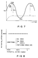
- Figures 6 and 7 are graphs illustrating vibration of the charge potential of the photosensitive drum in the area where the charging roller and the photosensitive drum are cross to each other.
- Figure 8 is a graph showing a relationship between the potential of the photosensitive drum prior to the charging and that after the charging.
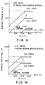
- Figures 9 and 14 are graphs showing relationships between a peak-to-peak voltage Vpp of the applied voltage and the surface potential V of the photosensitive member when an OPC photosensitive drum and an amorphous silicon photosensitive drum is used, respectively.
- Figures 10 and 13 are graphs showing relationships between a DC voltage V DC and the surface potential of the photosensitive member V when an OPC photosensitive drum and an amorphous silicon photosensitive drum are used, respectively.
- Figure 11 is a schematic view illustrating a gap between the photosensitive layer and the charging roller.
- Figure 12 is a graph showing a relationship between the Paschen's curve and a gap voltage.
- the image forming apparatus comprises a sheet feeding station A and a laser beam printing station B in combination.
- the printer station B is provided with an outer casing 1.
- the front side of the apparatus is shown in this Figure as the righthand side.
- the outer casing 1 includes a front plate 1A which is pivotable about a hinge 1B disposed at a bottom portion, so that the front plate 1A may be opened as shown by chain lines or closed as shown by solid lines in this Figure.
- the front plate 1A is opened to allow wide access to the inside thereof.
- the process cartridge 2 in this embodiment includes a cartridge housing 2a and contains therein a photosensitive drum 3, a charging roller 4, a developing device 5 and a cleaner 6 as image forming process means. It is detachably mountable into the printer casing 1 at a predetermined accommodating position when the front plate 1A is opened as shown by chain lines.
- the present invention is conveniently usable when the process cartridge 2 contains at least a photosensitive drum 3 (an image bearing member) and a charging roller 4 (charging member).
- one of the photosensitive drum 3 and the charging roller 4 may be substantially permanently fixed in the main assembly of the apparatus.
- the present invention is applicable where the developing device 5 or the cleaner 6 is not contained in the cartridge 2 or where another process means is contained in the cartridge.
- the outer casing 1 contains a laser beam scanner 7 disposed at a rear side therein, and the laser beam scanner 7 includes a semiconductor laser, a scanner motor 7a, a rotatable scanning mirror 7b such as a polygonal mirror, a lens system 7c and others.
- the laser beam L from the scanner 7 travels substantially horizontally through an exposure window 2b of the cartridge housing 2a of the cartridge mounted therein, the laser beam L further travels between the cleaner 6 and the developing device 5 disposed at upper and lower sides, respectively. It reaches the left side of the photosensitive drum 3 at the exposure station 3a.
- the photosensitive drum 3 surface is scanned in the direction of its generating line and is exposed to the laser beam.
- the apparatus further comprises a multi-feeding tray 8 which extends out of the front plate 1A and which is inclined upwardly toward outside. A plurality of sheet materials S can be set therein.
- the apparatus further includes a sheet feeding roller 10 disposed at a lower portion inside the front plate 1A, a conveying roller 12 in rolling contact with a left side of the feeding roller 10, an image transfer roller 13 disposed above the feeding roller 10 inside the front plate 1A, a couple of image fixing rollers 15a and 15b disposed at an upper portion inside the front plate 1A, a sheet guiding plate 14 disposed between the transfer roller 13 and the fixing roller couple 15a and 15b, a sheet material discharging roller 16 disposed at a sheet outlet side of the fixing roller couple 15a and 15b and a tray 17 for receiving the sheet materials discharged from the apparatus.
- the photosensitive drum 3 When an image formation start signal is inputted into the control system of the printer, the photosensitive drum 3 is rotated at a predetermined peripheral speed in the clockwise direction as indicated by an arrow. During the rotation, the periphery thereof is uniformly charged to a predetermined polarity, positive or negative by the charging roller 4.
- the charging roller 4 is of a conductive material to which a predetermined voltage is applied.
- the photosensitive drum 3 is charged by the roller contacted thereto.
- the charging roller 4 may be driven by the contact of the photosensitive drum 3 or may be positively rotated in the opposite directions. Also, the charging roller 4 may be non-rotatable.
- the charging roller 4 is positively rotated in the same peripheral direction and at the same peripheral speed as the rotation of the photosensitive drum 3, or that the charging roller 4 follows the photosensitive drum 3. This is because the friction between the roller and the drum is smaller than when there is a peripheral speed difference therebetween, and therefore, the problem of the wear and the scraping or the drum of the roller is reduced.
- the surface of the photosensitive drum 3 having been uniformly charged is exposed, at the exposure station 3a, to the laser beam L bearing time series picture element signals representing image information to be printed produced by the laser beam scanner 7, so that the photosensitive drum 3 surface is subjected to the main scan operation by the laser beam L in the direction of the generating line of the drum, by which an electrostatic latent image of the image information is formed on the photosensitive drum 3 surface.
- the electrostatic latent image thus formed on the photosensitive drum 3 is sequentially developed with a developer carried on a developing sleeve (or roller) 5a of the developing device 5 into a toner image.
- the developing device 5 includes a toner accommodating chamber 5b for accommodating the developer (toner).
- the latent image is formed by projecting a laser beam spot L at the image area of the surface of the photosensitive drum 3 which has been uniformly charged, so that the charge is removed from the photosensitive drum 3. Therefore, the developing operation is a reversal development by which the developer having the same polarity as the polarity of the charge remained on the photosensitive drum 3, so that the toner is deposited at the portion exposed to the laser beam.
- the topmost sheet of the sheets (transfer material) S accommodated in the multi-feeding tray 8 is introduced into the printer by the feeding roller 10 which is rotating in the direction indicated by an arrow.
- the sheet is conveyed into the nip formed between the feeding roller 10 and the conveying roller 12 and is advanced at a constant speed substantially equal to the peripheral speed of the photosensitive drum into the contact area between the photosensitive drum 3 and the transfer roller 13 constituting a transfer station.
- the sheet S fed into the transfer station receives the toner image from the surface of the photosensitive drum 3 during its passage between the photosensitive drum 3 and the transfer roller 13 by the function of the voltage of a polarity opposite to that of the toner applied to the transfer roller 13 and the pressure between the transfer roller 13 and the photosensitive drum 3.
- the application of the voltage to the transfer roller 13 starts when the leading edge of the sheet S reaches the contact portion (transfer portion) between the photosensitive drum 3 and the transfer roller 13.
- a transfer roller is employed as the transfer means, however, a corona charger may be used in place thereof.
- the transfer sheet S having passed through the transfer portion is separated from the photosensitive drum 3 surface, and is guided by the guiding plate 14 to the fixing roller couple 15a and 15b.
- the roller 15a is adapted to be contacted to such a side of the transfer sheet as bears the transferred image and is provided with a halogen heater to constitute a heating roller
- the roller 15b is adapted to contact the back side of the sheet material and is made of an elastic material to constitute a pressing roller.
- the sheet material now having the transferred image is fixed while being passed through the nip between the rollers 15a and 15b, by which the toner image is fixed on the surface of the sheet material by heat and pressure into a permanent image.
- the sheet is then discharged onto the tray 17 by the discharging roller 16 as a print or copy.
- the surface of the photosensitive drum 3 after the toner image is transferred is subjected to the cleaning operation by the cleaner 6 having the cleaning blade 6a, so that the residual toner or other contaminations are wiped out to be prepared for the next image forming operation.
- a cassette 40 of the sheet feeding device A is usable in place of the multi-feeding tray 8.
- the topmost sheet material in the cassette 40 is picked up and advanced to the registration rollers 28 and 55 by the pickup roller 26 and is transported to between the feeding roller 10 and the conveying roller 12, in the manner described above.
- the photosensitive drum 3 is made of OPC (organic photoconductor), but may be of amorphous silicon, selenium ZnO or other photosensitive material.
- OPC organic photoconductor
- the charging of the photosensitive member is effected by the charging member contacted to the surface of the photosensitive member.
- the charging roller 4 includes a core metal and a conductive rubber layer thereon. At least the surface of the charging roller 4 is electrically conductive, and the resistance is 102 - 108 ohm preferably. In this embodiment, a conductive urethane rubber roller having the resistance 105 ohm is used. Here, the resistance is the one from the core metal to the roller surface per 1 cm2 of the roller surface area. As the material of the roller, EDDM, NBR and CR are usable.
- the charging roller 4 is always press-contacted to the surface of the photosensitive member 3 under a predetermined pressure, for example, a line pressure of 0.01 - 0.2 kg/cm. In this embodiment, the charging roller 4 follows the rotation of the photosensitive member 3.
- a voltage application source 21 for the charging roller 4 includes a DC source 22, an AC source 23 and a switch 24.
- the switch 24 of the voltage source 21 is contacted to an A side, by which the charging roller 4 is supplied with a vibrating voltage which is a combination of a DC voltage V DC provided by the DC source 22 and an alternating voltage V AC provided by the alternating current source 23, so that the charging roller 4 is supplied with a superimposed DC voltage and AC voltage, V DC + V AC .
- the vibrating voltage is a voltage which changes periodically with time.
- center of vibration is defined as (Vmax Vmin)/2, that is, the middle of the maximum voltage and the minimum voltage in one period.
- the DC source produces -700 V DC voltage
- the waveform of the vibration is in the form of a sine curve.
- the uniform potential is achieved by the feature of the voltage settings, a charge starting voltage V TH when only a DC voltage is applied to the charging roller and the peak-to-peak voltage Vpp of the AC voltage component satisfy Vpp ⁇ 2
- the charge starting voltage is determined in the following manner. Only DC component is applied to the charging member contacted to the image bearing member (photosensitive member) having a zero surface potential. The voltage of the DC component is gradually increased. The surface potentials of the photosensitive member are plotted with respect to the DC voltage applied thereto with a predetermined increment of the voltage, for example, 100 volts. The first point of the voltage is the one at which the surface potential of the photosensitive member appears, and about ten surface potential are plotted at each 100 volt increment, for example. Using least square approximation, a straight line is drawn from the plots. The DC voltage reading at which the straight line and, the line representing the zero surface potential intersect is taken as the charge starting voltage.
- Figures 10 and 13 are the graphs produced in the above-described manner.
- the photosensitive layer 1b of the photosensitive drum includes a CGL (carrier generating layer) of azo pigment and CTL (carrier transfer layer) having a thickness of 19 microns and containing a mixture of hydrazone and resin.
- the photosensitive layer is an OPC (organic photoconductor) layer of a negative property.
- the OPC drum is rotationally driven, to the surface of which the charging roller 4 is contacted.
- the charging roller 4 is supplied with a DC voltage V DC to effect the charging to the OPC photosensitive drum in the dark.
- the surface potential V of the OPC photosensitive drum 1 charged by the charging roller 4 and the DC voltage V DC applied to the charging roller 4 were measured.
- Figure 10 shows the results of measurements.
- the charging action involves a threshold concerning the DC voltage V DC applied.
- the charging effect starts at approximately 560 V.
- the provided surface potential V by the applied voltage higher than the charge starting voltage is linear with respect to the applied voltage as shown in Figure 10.
- the property is substantially immune to ambient conditions, that is, generally the same results are confirmed under high humid and high temperature conditions (32.5 °C and 85 %, for example) and under low-humid and low temperature conditions (15 °C and 10 %, for example).
- Vc Va - V TH Va: DC voltage applied to the charging roller 4; Vc: potential of the surface of the OPC photosensitive drum; V TH : charge starting voltage.
- Vg [(Va-Vc)Z]/(Ls/Ks+Z)
- Figure 13 is a graph showing the results of measurements of the DC voltage applied to the charging roller 4 and the surface potential of the photosensitive drum after being charged by the charging roller 4, when the photosensitive layer of the photosensitive drum is replaced by an amorphous silicon photosensitive drum.
- V TH 432 V, which is substantially the same as results of experiments.
- the inventors applied a vibratory voltage provided by a DC voltage and an AC voltage superposed therewith to the charging roller. As a result, it has been found that it is effective for elimination of the non-uniformness to superpose to the DC voltage an AC voltage having a certain level of peak-to-peak voltage.
- the OPC photosensitive drum and amorphous silicon photosensitive drum are the same as the ones used in paragraph (1).
- a vibratory voltage (V DC +V AC ) provided by superposing a DC voltage V DC and an AC voltage V AC having a peak-to-peak voltage Vp-p is applied to the charging roller 4 to contact-charge the amorphous silicon and OPC photosensitive drum, respectively.
- the peak-to-peak voltage and the charged potential of the surface of the photosensitive drum were measured.
- the potential increases substantially linearly proportionally with Vp-p.
- the potential levels are substantially at the V DC level of the DC component of the applied voltage and becomes substantially constant irrespective of increase of Vp-p.
- the inflection point ⁇ with respect to Vp-p is approx. 1100 V as shown in Figure 9 in the case of OPC photosensitive drum, and approx. 900 V in the case of the amorphous silicon drum as shown in Figure 14. These are approximately twice the charge starting voltage V TH when the DC voltage is applied (paragraph (1)).
- Vp-p When the level of Vp-p is small, that is, when there is a linear relationship between Vp-p/2 and the charged potential (inclination is 1), a spotty charging results like when a DC voltage alone is applied to the charging roller 4. However, where the peak-to-peak voltage higher than the inflection point ⁇ is applied, the charged potential level is constant, and the resultant visualized image is uniform, that is, the charging is uniform.
- a vibratory voltage having a peak-to-peak voltage which is not less than twice the absolute value of the charge starting voltage V TH when a DC voltage is applied determined on the basis of the various properties or the like of the photosensitive member which is a member to be charged.
- the surface potential of the photosensitive member provided is dependent on the DC component of the voltage applied.
- the inflection point ⁇ is considered to be a starting point where the electric charge starts to transfer back from the photosensitive member to the charging roller under the vibratory field between the photosensitive member and the charging roller, provided by the vibratory voltage application.
- FIG. 6 shows a waveform of the applied voltage to the charging roller in the area where the charging roller is close to the photosensitive member (solid line) and the surface potential of the photosensitive member (broken lines).
- Vc Va - V TH
- V V DC + Vp-p/2 - V TH .
- the charge transfers and transfers back therebetween, wherein the charge transfer is depedent on the threshold V TH . If it is assumed that the charge movement occurs when a potential difference not less than the threshold V TH is produced at a predetermined distance, in the area where the charging roller and the photosensitive drum are close to each other, the charge potential of the photosensitive drum vibrates in the manner shown in Figure 6 by broken line, which is similar to a pulse wave. As seen from the Figure, the amplitude is Vp-p/2 - V TH .
- the back transition of the charge from the photosensitive member to the charging roller occurs, so that it approaches V TH .
- the applied voltage becomes Vmin
- the difference between the applied voltage and the surface potential of the photosensitive member becomes V TH
- the charge transition does not occur.
- the surface potential of the photosensitive member vibrates in the waveform somewhat like a pulse wave as shown by broken lines having an amplitude of (Vpp/2 - V TH ).
- the threshold voltage V TH is the potential difference in the closest portion where the charge transition occurs, and is dependent on the distance. More particularly, the threshold voltage V TH required for the charge to transit increases with a gap between the charging roller 4 and the photosensitive member.
- the surface potential of the photosensitive member reaches -700 V when a DC voltage of -1200 to -1300 V is applied, but the uniformity of the charge is not good.
- the photosensitive member 1 is repeatedly used, the potential contrast caused by the previous electrostatic latent image remains with the result of ghost image produced.
- the surface of the photosensitive member 3 is electrically discharged to make it suitable for the resting.
- an AC component is applied to the charging roller 4 with the DC component being zero.
- the switch 24 of the power source 21 is switched to contact B and is maintained, during the post-rotation which continues at least one full turn of the photosensitive member.
- the voltage applied to the charging member is small, so that the switching is easier than when a corona discharging device requiring a high voltage is used.
- the voltage applied to the charging roller 4 switches from the superposed AC and DC voltage to an AC voltage V AC only.
- the center of the vibration changes from V DC to zero, in the photosensitive member discharging operation.
- the surface potential of the photosensitive member 3 becomes uniformly zero substantially. It has been confirmed that the surface of the photosensitive member is discharged similarly when the frequency of the AC component is 500 Hz, 1000 Hz, 1500 Hz and 2000 Hz.
- is satisfied.
- the AC voltage component is not changed when the photosensitive member discharging operation is effected since then the structure of the apparatus is simple. However, it may be changed as long as Vpp ⁇ 2
- the photosensitive member discharging operation continues for at least one full turn of the photosensitive member, so that the entire surface of the photosensitive member 3 is electrically discharged. Thereafter, the AC voltage is shut, and the rotation of the photosensitive member 3 is stopped.
- the potential remaining on the photosensitive member is attenuated before the apparatus is stopped or it is put into stand-by state, after the image forming operation using the photosensitive member is repeated.
- the voltage applied to the charging roller is changed to a vibrating voltage having a center of vibration equal to zero (a pure AC voltage).
- the level of the DC voltage component may be changed from -700 V (image forming operation) to, for example, -100 V upon discharging operation.
- the charging roller 4 is supplied with a superposed voltage of a second DC voltage V DC (-100 V) and a sine wave AC voltage V AC having the peak-to-peak voltage of Vpp of 1500 V and the frequency of 1000 Hz.
- the center of the vibrating voltage is changed from -700 V to -100 V, and therefore, the absolute value of the center of the vibrating voltage is reduced upon the photosensitive member discharging operation.
- the surface potential of the photosensitive member 3 reduces to -100 V in its entire surface. It has been confirmed that the same results are provided when the frequency is 500 Hz, 1500 Hz and 2000 Hz.
- the potential of -100 V is comparable to the potential when the photosensitive member is discharged by the whole surface exposure.
- is satisfied. It is also preferable that the AC voltage upon the photosensitive member discharging operation is the same as that upon the charging operation. However, it may be changed as long as Vpp ⁇ 2
- the center of the vibratory voltage after the image formation is set -100 V, but it may be changed depending on the photosensitive members used, so that the property of the photosensitive member does not change even if it is kept unused.
- the potential is set lower than the potential resulted when the photosensitive member is substantially discharged by exposure to strong light.
- the potential resulted by the strong exposure is the saturated potential.
- the saturated potential When a photosensitive member having electric charge is exposed to light, the surface potential thereof attenuates; and the surface potential decreases with the intensity of the light; however, the surface potential does not change at a certain point even if the intensity is increased; and this is called the saturated potential.
- the absolute value of the center of the vibrating voltage is not more than 100 V.
- the switch 24 is switched to the contact B, that is, the grounded contact, and this is maintained.
- the charging roller 4 is grounded.
- the surface potential remaining on the photosensitive 3 is reduced by the charging roller 4, similarly to the case that only the AC voltage is applied to the charging roller 4.
- the charging effect is weaker than in the case where the AC voltage is positively applied.
- the entire surface of the photosensitive member is satisfactorily discharged by setting the number of the post-rotations to be plural.
- the photosensitive member 3 is supposed to rotate through plural turns after the image forming operation is completed and before the last transfer sheet S is fixed and discharged. During this plural turns, the photo-sensitive member discharging operation can be performed, by which the photosensitive member 3 is sufficiently uniformly discharged in its entire surface.
- the charging roller is grounded upon the photosensitive member discharging operation.
- the photosensitive member can be discharged by applying a DC voltage having a polarity opposite to that of the potential of the photosensitive member remaining charged.
- the resultant surface potential of the photosensitive member is more or less non-uniform.
- the photosensitive member discharging operation is performed during the post-rotation of the photosensitive drum (image bearing member) after the image forming operation is completed, but it may be performed during the pre-rotation.
- the portion of the photosensitive member corresponding to an image portion of an original is exposed to light after the photosensitive member is uniformly charged; and the charge of the exposed portion is removed; and a developer charged to a polarity opposite to the polarity of the charge is deposited onto the charge remaining portion
- the apparatus stops with the charge remaining on the photosensitive member. If this occurs, it is desirable that the photosensitive member is electrically discharged by at least one full-turn of the photo-sensitive member before the resumption of the image formation, so as to dissipate the charge on the photosensitive member. This may be effected, substantially simultaneously with the main switch of the image forming apparatus being turned on. Also, in the case of the regular development in the repeated image forming cycle, the electric charge is retained on an area of the photosensitive member between the first image and the second image, for example, the charge retaining portion is developed although it is not desired. Therefore, it is preferable to electrically discharge the photosensitive member between adjacent images, in the case of the regular development.
- the charging roller is in contact with the photosensitive member to charge or discharge the photosensitive member.
- a conductive rubber blade used in place of the roller.
- the blade is somewhat less durable than the roller.
- the blade is advantageous from the standpoint of manufacturing cost.
- a sine wave is used for the waveform of the vibratory voltage, but it may be a pulse wave, a triangular wave or rectangular wave.
- the image forming process is not limited to a so-called Carlson process employed in the foregoing embodiments, but the present invention is applicable to various processes known as including a step of uniformly charging the image bearing member.
- the image exposure means may be of a type wherein an original supporting platen is moved or an original supporting platen is fixed with an optical system movable, and may be of LED array control type, a liquid crystal array control system or other various means.
- the charging means and charge removing means actionable on the image bearing member can be one and the same member.
- the charging member is supplied with a vibratory voltage having a center of vibration which has an absolute value smaller than the absolute value of the center of the vibratory voltage at the time of the charging operation.
- the discharging vibratory voltage has a center of vibration of zero volts (the ground potential) then, it is not necessary to employ both pre-discharging means conventionally used exclusively for the pre-discharge and post-discharging means conventionally used exclusively for the post-discharge. Because of the elimination of the necessity for two charging members, the image forming apparatus of this type can be made smaller, simpler and less expensive.
- the charging means includes a charging member supplied with a vibratory voltage contacted to the image bearing member, such a high voltage as has to be employed in a corona discharger for charging and discharging the image bearing member is not required, whereby the charging efficiency is increased, and the production of ozone is decreased, and the charging and discharging becomes uniform and stabilized.
Claims (26)
- Bilderzeugungsgerät mit
einem bewegbaren Bildträgerteil (3) mit einer lichtempfindlichen Schicht, auf der ein Bild wiederholt erzeugt werden kann,
einer Einrichtung (4, 5, 7) zum Erzeugen eines Bildes auf dem Teil (3),
einem Ladeteil (4) zum elektrischen Laden des Bildträgerteils (3) und
einer Spannungsspeiseeinrichtung (21) zum Speisen des Ladeteils mit einer Spannung,
dadurch gekennzeichnet, daß
das Ladeteil (4) das Bildträgerteil (3) berührt und daß
das Gerät in einer ersten und einer zweiten Betriebsart betrieben werden kann, bei der die Spannungsspeiseeinrichtung (21) das Ladeteil (4) jeweils mit einer ersten Wechselspannung mit einem Schwingungs-Mittelpunkt speist, damit das Bildträgerteil (3) aufgeladen wird, und mit einer zweiten Wechselspannung mit einem Schwingungs-Mittelpunkt speist, dessen Absolutwert geringer als der der ersten Wechselspannung ist, damit das Bildträgerteil (3) entladen wird. - Gerät nach Anspruch 1, dadurch gekennzeichnet, daß jede Wechselspannung durch Überlagern eines Gleichspannungsanteils und eines Wechselspannungsanteils erzeugt wird, wobei der Absolutwert des Gleichspannungsanteils der zweiten Wechselspannung kleiner als der Absolutwert des Gleichspannungsanteils der ersten Wechselspannung ist.
- Gerät nach Anspruch 1 oder 2, dadurch gekennzeichnet, daß die erste und die zweite Wechselspannung einen gemeinsamen Wechselspannungsanteil aufweisen.
- Gerät nach einem der vorangehenden Ansprüche, dadurch gekennzeichnet, daß die Spitze-Spitze-Spannung jeder dem Ladeteil (4) zugeführten Wechselspannung nicht weniger als das Doppelte des Absolutwertes des Mindestwertes der Gleichspannung beträgt, die bei Anlegen an das Ladeteil (4) die Aufladung des Bildträgerteils (3) auslösen würde.
- Gerät nach einem der vorangehenden Ansprüche, dadurch gekennzeichnet, daß der Gleichspannungsanteil der zweiten Wechselspannung Null ist.
- Gerät nach einem der vorangehenden Ansprüche, dadurch gekennzeichnet, daß die Spannungsspeiseeinrichtung (21) eine Einrichtung (22, 23, 24) zum wahlweisen Speisen des Ladeteils mit überlagerten Wechsel- und Gleichspannungsanteilen als erste Wechselspannung, damit das Bildträgerteil aufgeladen wird, und zum Speisen nur des Wechselspannungsanteils als zweite Wechselspannung enthält, damit das Bildträgerteil entladen wird.
- Gerät nach einem der vorangehenden Ansprüche, gekennzeichnet durch eine Steuereinrichtung (24) zum aufeinanderfolgenden Auswählen der ersten Wechselspannung, dann der zweiten Wechselspannung und dann zum Abschalten der zweiten Wechselspannung.
- Gerät nach einem der vorangehenden Ansprüche, dadurch gekennzeichnet, daß die erste und die zweite Wechselspannung eine Sinusform aufweisen.
- Gerät nach einem der vorangehenden Ansprüche, dadurch gekennzeichnet, daß das Ladeteil eine drehbare Walze ist.
- Gerät nach einem der vorangehenden Ansprüche, dadurch gekennzeichnet, daß das Ladeteil eine Oberflächenschicht aus einem leitfähigen Gummimaterial enthält.
- Gerät nach einem der vorangehenden Ansprüche, dadurch gekennzeichnet, daß das Bildträgerteil entweder eine Schicht aus organischem Photoleiter oder eine lichtempfindliche Schicht aus amorphem Silizium aufweist.
- Gerät nach einem der vorangehenden Ansprüche, dadurch gekennzeichnet, daß das Bildträgerteil drehbar ist und daß das Ladeteil gesteuert werden kann, damit das Bildträgerteil während zumindest einer Drehung nach einem Bilderzeugungsvorgang darauf elektrisch entladen wird.
- Gerät nach einem der vorangehenden Ansprüche, dadurch gekennzeichnet, daß das Bildträgerteil und das Ladeteil sich derart bewegende Oberflächen aufweisen, daß sich ein Abschnitt des Bildträgerteils, der anfänglich das Ladeteil berührt, in zunehmendem Maße von der Oberfläche des Ladeteils in der stromab führenden Bewegungsrichtung des Bildträgerteils trennt, so daß nach Passieren des Berührabschnitts ein Punkt auf dem Bildträgerteil während einer Vielzahl von Perioden der Wechselspannung nahe dem Ladeteil verbleibt.
- Gerät nach einem der vorangehenden Ansprüche, gekennzeichnet durch eine Einrichtung (7) zum Erzeugen eines Latentbildes, das einem Bild zur Erzeugung auf dem Bildträgerteil entspricht, nachdem das Bildträgerteil aufgeladen worden ist, und eine Einrichtung (5) zum Entwickeln des Latentbildes.
- Gerät nach einem der vorangehenden Ansprüche, dadurch gekennzeichnet, daß die Bilderzeugungseinrichtung eine Belichtungseinrichtung (7) enthält, damit das Bildträgerteil einem Bildinformations-Licht ausgesetzt wird.
- Gerät nach Anspruch 15, gekennzeichnet durch eine Bildübertragungseinrichtung (13) zum Übertragen eines Bildes von dem Bildträgerteil zu einem Übertragungsmaterial, wobei das Bildträgerteil nach der Bildübertragung durch die Bildübertragungseinrichtung und vor der Aufladung durch das Ladeteil keinem Licht ausgesetzt wird.
- Gerät nach Anspruch 15, dadurch gekennzeichnet, daß das Bildträgerteil ein lichtempfindliches Teil ist und daß ein Absolutwert des Schwingungs-Mittelpunkts der zweiten Wechselspannung nicht größer als der Absolutwert des Sättigungspotentials des lichtempfindlichen Teils ist, wenn es aufgeladen und durch die Belichtungseinrichtung belichtet worden ist.
- Gerät nach Anspruch 15, gekennzeichnet durch eine Reinigungsvorrichtung (6) zum Entfernen von restlichem Entwickler von dem Bildträgerteil (3), wobei das Ladeteil zwischen der Reinigungsvorrichtung und der Belichtungseinrichtung in Bewegungsrichtung des Bildträgerteils angeordnet ist.
- Gerät nach einem der vorangehenden Ansprüche, dadurch gekennzeichnet, daß das Ladeteil und das Bildträgerteil in einem Arbeitseinheits-Gerät (2) befestigt sind, das abnehmbar in das Bilderzeugungsgerät eingesetzt werden kann.
- Gerät nach einem der Ansprüche 1 bis 19, dadurch gekennzeichnet, daß das Bildträgerteil drehbar ist und daß das Ladeteil gesteuert werden kann, damit das Bildträgerteil während zumindest einer Drehung vor einem Bilderzeugungsvorgang darauf elektrisch entladen wird.
- Arbeitsverfahren eines Bilderzeugungsgerätes zum Aufladen eines Bildträgerteils mit einer lichtempfindlichen Schicht, dadurch gekennzeichnet, daß es die Schritte der Speisung eines Ladeteils, das das Bildträgerteil berührt, mit einer ersten Wechselspannung mit einem Schwingungs-Mittelpunkt und der Speisung des Ladeteils mit einer zweiten Wechselspannung mit einem Schwingungs-Mittelpunkt aufweist, dessen Absolutwert geringer als der der ersten Wechselspannung ist, damit das Bildträgerteil entladen wird.
- Verfahren nach Anspruch 21, dadurch gekennzeichnet, daß die erste und die zweite Wechselspannung jeweils durch Überlagern eines Gleich- und eines Wechselspannungsanteils erzeugt werden, wobei der Absolutwert des Gleichspannungsanteils der zweiten Wechselspannung kleiner als der Absolutwert des Gleichspannungsanteils der ersten Wechselspannung ist.
- Verfahren nach Anspruch 22, dadurch gekennzeichnet, daß die Wechselspannungsanteile der ersten und zweiten Wechselspannungen dieselben sind.
- Verfahren nach Anspruch 21 oder 22, dadurch gekennzeichnet, daß die Spitze-Spitze-Spannung jeder der dem Ladeteil zugeführten Wechselspannung nicht geringer als das Doppelte des Mindestwertes der Gleichspannung ist, die bei Anlegen an das Ladeteil die Aufladung des Bildträgerteils auslösen würde.
- Verfahren nach einem der Ansprüche 21 bis 24, dadurch gekennzeichnet, daß die erste und die zweite Wechselspannung eine Sinusform aufweisen.
- Verfahren nach einem der Ansprüche 21 bis 25, dadurch gekennzeichnet, daß der Absolutwert des Schwingungs-Mittelpunkts der zweiten Wechselspannung nicht mehr als 100 V beträgt.
Applications Claiming Priority (4)
| Application Number | Priority Date | Filing Date | Title |
|---|---|---|---|
| JP4384487A JPS63208881A (ja) | 1987-02-26 | 1987-02-26 | 画像形成装置 |
| JP43844/87 | 1987-02-26 | ||
| JP313905/87 | 1987-12-11 | ||
| JP31390587A JPH01154175A (ja) | 1987-12-11 | 1987-12-11 | 画像形成装置 |
Publications (3)
| Publication Number | Publication Date |
|---|---|
| EP0280542A2 EP0280542A2 (de) | 1988-08-31 |
| EP0280542A3 EP0280542A3 (en) | 1988-10-19 |
| EP0280542B1 true EP0280542B1 (de) | 1994-11-02 |
Family
ID=26383681
Family Applications (1)
| Application Number | Title | Priority Date | Filing Date |
|---|---|---|---|
| EP88301603A Expired - Lifetime EP0280542B1 (de) | 1987-02-26 | 1988-02-25 | Bilderzeugungsgerät |
Country Status (3)
| Country | Link |
|---|---|
| US (2) | US5164779A (de) |
| EP (1) | EP0280542B1 (de) |
| DE (1) | DE3851968T2 (de) |
Families Citing this family (56)
| Publication number | Priority date | Publication date | Assignee | Title |
|---|---|---|---|---|
| USRE35581E (en) * | 1986-12-15 | 1997-08-12 | Canon Kabushiki Kaisha | Charging device |
| US4851960A (en) * | 1986-12-15 | 1989-07-25 | Canon Kabushiki Kaisha | Charging device |
| DE3851968T2 (de) * | 1987-02-26 | 1995-03-30 | Canon Kk | Bilderzeugungsgerät. |
| DE3854559T2 (de) * | 1987-03-31 | 1996-03-21 | Canon Kk | Bilderzeugungsgerät. |
| JPH07113802B2 (ja) * | 1987-06-30 | 1995-12-06 | キヤノン株式会社 | 画像形成装置 |
| JPH0693150B2 (ja) * | 1988-04-20 | 1994-11-16 | キヤノン株式会社 | 画像形成装置 |
| US5307122A (en) * | 1989-07-28 | 1994-04-26 | Canon Kabushiki Kaisha | Image forming apparatus apparatus unit facsimile apparatus and developer comprising hydrophobic silica fine powder for developing electrostatic images |
| JPH03156476A (ja) * | 1989-11-15 | 1991-07-04 | Canon Inc | 画像形成装置の帯電装置 |
| JPH03240076A (ja) * | 1990-02-17 | 1991-10-25 | Canon Inc | 帯電装置 |
| KR970005219B1 (ko) * | 1990-09-14 | 1997-04-14 | 캐논 가부시끼가이샤 | 화상기록장치 |
| DE69128998T2 (de) * | 1990-10-26 | 1998-07-30 | Canon Kk | Entwickler zur Entwicklung elektrostatischer Bilder, Bilderzeugungsverfahren, elektrographischer Apparat, Geräteeinheit und Faksimile-Apparatur |
| JP2817391B2 (ja) * | 1990-11-02 | 1998-10-30 | キヤノン株式会社 | 帯電装置 |
| EP0511844B1 (de) * | 1991-04-30 | 1996-07-10 | Canon Kabushiki Kaisha | Elektrophotographisches Gerät |
| JP2561400B2 (ja) * | 1991-07-31 | 1996-12-04 | キヤノン株式会社 | 電子写真装置及びこの装置に着脱可能なプロセスカートリッジ |
| JP3262346B2 (ja) * | 1991-07-31 | 2002-03-04 | キヤノン株式会社 | 帯電装置及び帯電装置を有するプロセスカートリッジ又は画像形成装置 |
| EP0534437B1 (de) * | 1991-09-27 | 1997-06-11 | Bridgestone Corporation | Kontaktaufladegerät und Verfahren |
| JP2907614B2 (ja) * | 1991-12-19 | 1999-06-21 | 三田工業株式会社 | 機能冗長系を有する画像形成装置 |
| US5412455A (en) * | 1992-01-30 | 1995-05-02 | Canon Kabushiki Kaisha | Charging device, image forming apparatus and detachably mountable process cartridge having a constant voltage power source feature |
| DE69325113T2 (de) * | 1992-02-07 | 1999-11-04 | Canon Kk | Bilderzeugungsgerät mit einem Auflade-Element in Kontakt mit dem Bildträgerelement |
| JP3259985B2 (ja) | 1992-09-04 | 2002-02-25 | キヤノン株式会社 | プロセスカートリッジ及び画像形成装置 |
| US5426488A (en) * | 1992-10-19 | 1995-06-20 | Sharp Kabushiki Kaisha | Method of charging a built-in electrophotographic charge member |
| US5552865A (en) * | 1993-02-09 | 1996-09-03 | Minolta Camera Kabushiki Kaisha | Charging device and method for charging a charge-receiving member by a charging member by discharge therebetween based on difference in electric potential between the charging member and the charge-receiving member |
| JPH06314016A (ja) * | 1993-04-28 | 1994-11-08 | Konica Corp | 帯電装置 |
| US6004031A (en) * | 1993-11-30 | 1999-12-21 | Nkk Corporation | Temperature measuring device |
| JP2795146B2 (ja) * | 1993-11-30 | 1998-09-10 | 日本鋼管株式会社 | 測温用二重被覆光ファイバ |
| JPH07244419A (ja) * | 1994-03-04 | 1995-09-19 | Fuji Xerox Co Ltd | 電子写真法 |
| JPH07306569A (ja) * | 1994-05-11 | 1995-11-21 | Canon Inc | 帯電部材、帯電装置、画像形成装置、及びプロセス カートリッジ |
| KR200153521Y1 (ko) * | 1996-02-17 | 1999-09-01 | 윤종용 | 전자 사진 인쇄장치의 보조 대전 장치 |
| KR0174698B1 (ko) * | 1996-03-18 | 1999-04-01 | 김광호 | 전자사진 현상방식을 이용하는 장치의 대전전압 제어방법 |
| KR100193828B1 (ko) * | 1996-06-25 | 1999-06-15 | 윤종용 | 전자사진 현상방식을 채용한 화상형성장치의 화상농도 조정장치 |
| KR100191203B1 (ko) * | 1997-03-14 | 1999-06-15 | 윤종용 | 전자사진 현상방식을 채용한 화상형성장치의 전사 바이어스 제어방법 |
| US5911097A (en) * | 1997-03-18 | 1999-06-08 | Minolta Co., Ltd. | Image forming apparatus and method using charge control means |
| US6075955A (en) * | 1998-01-23 | 2000-06-13 | Mitsubishi Chemical America, Inc. | Noise reducing device for photosensitive drum of an image forming apparatus |
| JP2001235929A (ja) * | 2000-02-24 | 2001-08-31 | Canon Inc | 画像形成装置 |
| JP2002023480A (ja) * | 2000-07-06 | 2002-01-23 | Canon Inc | 画像形成装置 |
| US6842594B2 (en) * | 2002-12-13 | 2005-01-11 | Xerox Corporation | Intermittent DC bias charge roll AC cleaning cycle |
| US7085507B2 (en) * | 2003-08-25 | 2006-08-01 | Lexmark International, Inc. | Method and apparatus to control waste toner collection in an image forming apparatus |
| US7092659B2 (en) * | 2003-12-31 | 2006-08-15 | Samsung Electronics Co., Ltd. | Discharge methods and systems in electrophotography |
| US7205738B2 (en) * | 2004-03-24 | 2007-04-17 | Lexmark International, Inc. | Method and apparatus for time-based dc motor commutation |
| US7177572B2 (en) * | 2004-06-25 | 2007-02-13 | Xerox Corporation | Biased charge roller with embedded electrodes with post-nip breakdown to enable improved charge uniformity |
| US7257363B2 (en) | 2005-09-22 | 2007-08-14 | Lexmark International, Inc. | Device for moving toner within an image forming device |
| JP4994650B2 (ja) * | 2005-12-02 | 2012-08-08 | キヤノン株式会社 | 帯電装置 |
| JP2007219087A (ja) * | 2006-02-15 | 2007-08-30 | Fuji Xerox Co Ltd | 帯電装置及び画像形成装置 |
| KR101079579B1 (ko) * | 2007-02-02 | 2011-11-03 | 삼성전자주식회사 | 화상형성장치 및 그 화상형성방법 |
| US9170518B2 (en) | 2010-08-26 | 2015-10-27 | Xerox Corporation | Method and system for closed-loop control of nip width and image transfer field uniformity for an image transfer system |
| US8396404B2 (en) | 2010-08-26 | 2013-03-12 | Xerox Corporation | Image transfer nip method and apparatus using constant current controls |
| USRE48771E1 (en) | 2010-08-31 | 2021-10-12 | Northwest Podiatrie Laboratory, Inc. | Apparatus and method for imaging feet |
| US9778027B1 (en) | 2010-09-30 | 2017-10-03 | Northwest Podiatric Laboratory, Inc. | Apparatus and method for imaging feet |
| JP5704977B2 (ja) * | 2011-03-09 | 2015-04-22 | キヤノン株式会社 | 画像形成装置 |
| JP5393823B2 (ja) * | 2012-02-29 | 2014-01-22 | 京セラドキュメントソリューションズ株式会社 | クリーニング装置、およびこれを備える像担持体ユニット、画像形成装置 |
| US9523947B2 (en) | 2012-09-26 | 2016-12-20 | Lexmark International, Inc. | Time-based commutation method and system for controlling a fuser assembly |
| US8836747B2 (en) | 2012-10-02 | 2014-09-16 | Lexmark International, Inc. | Motor control system and method for a laser scanning unit of an imaging apparatus |
| US9014585B2 (en) | 2013-03-15 | 2015-04-21 | Xerox Corporation | System and method for detecting bias transfer roll positions using resistance detection |
| US10191407B2 (en) * | 2015-04-15 | 2019-01-29 | Hp Indigo B.V. | Applying a corrective voltage |
| JP2017058439A (ja) | 2015-09-15 | 2017-03-23 | 株式会社リコー | 画像形成装置及びその制御方法 |
| WO2020076318A1 (en) * | 2018-10-11 | 2020-04-16 | Hewlett-Packard Development Company, L.P. | Charge roller gap determination |
Family Cites Families (24)
| Publication number | Priority date | Publication date | Assignee | Title |
|---|---|---|---|---|
| US4123154A (en) * | 1977-03-03 | 1978-10-31 | Xerox Corporation | Combined corona generator and imaging surface cleaner |
| US4387980A (en) * | 1979-12-25 | 1983-06-14 | Tokyo Shibaura Denki Kabushiki Kaisha | Charging device for electronic copier |
| JPS56104347A (en) * | 1980-01-23 | 1981-08-20 | Toshiba Corp | Charging device of electrophotographic copier |
| DE3101678C2 (de) * | 1980-01-25 | 1983-07-07 | Tokyo Shibaura Denki K.K., Kawasaki, Kanagawa | Einrichtung zum gleichförmigen Aufladen eines kontinuierlich durch eine Aufladezone bewegten elektrofotografischen Aufzeichnungsmaterials |
| EP0035745B1 (de) * | 1980-03-10 | 1984-06-20 | Kabushiki Kaisha Toshiba | Aufladevorrichtung |
| JPS56132356A (en) * | 1980-03-21 | 1981-10-16 | Minolta Camera Co Ltd | Roller charger |
| JPS56143459A (en) * | 1980-04-10 | 1981-11-09 | Toshiba Corp | Electric charger |
| JPS56146157A (en) * | 1980-04-15 | 1981-11-13 | Sharp Corp | Corona charger serving as destaticizer |
| JPS5764755A (en) * | 1980-10-08 | 1982-04-20 | Toshiba Corp | Charging device |
| JPS5767951A (en) * | 1980-10-14 | 1982-04-24 | Toshiba Corp | Electric charger |
| US4470689A (en) * | 1981-06-02 | 1984-09-11 | Canon Kabushiki Kaisha | Image forming apparatus and process unit |
| JPS5849960A (ja) * | 1981-09-21 | 1983-03-24 | Toshiba Corp | ロ−ラ−帯電器 |
| JPS5854644A (ja) * | 1981-09-28 | 1983-03-31 | Nec Corp | ボンデイング用樹脂基板 |
| JPS58186762A (ja) * | 1982-04-24 | 1983-10-31 | Fuji Xerox Co Ltd | 荷電、除電兼用コロトロン |
| CA1214502A (en) * | 1982-11-01 | 1986-11-25 | Lloyd F. Bean | Cleaning method and apparatus for a xerographic reproducing apparatus |
| JPS6052870A (ja) * | 1983-09-02 | 1985-03-26 | Fuji Photo Film Co Ltd | 電子写真複写装置 |
| JPS6076360A (ja) * | 1983-10-03 | 1985-04-30 | Nec Corp | 感熱記録装置 |
| JPS60216361A (ja) * | 1984-04-12 | 1985-10-29 | Fuji Xerox Co Ltd | ブラシ帯電・転写装置 |
| JPS61198254A (ja) * | 1985-02-28 | 1986-09-02 | Toshiba Corp | 電子写真装置 |
| US4657369A (en) * | 1985-04-02 | 1987-04-14 | Kentek Information Systems, Inc. | Disposable photoconductive belt assembly for a printer or a copier |
| US4640599A (en) * | 1985-10-15 | 1987-02-03 | Pitney Bowes Inc. | Method and apparatus for neutralizing residual charge on a photoconductive surface |
| JPS62249178A (ja) * | 1986-04-22 | 1987-10-30 | Alps Electric Co Ltd | 電子写真式プリンタ |
| US4851960A (en) * | 1986-12-15 | 1989-07-25 | Canon Kabushiki Kaisha | Charging device |
| DE3851968T2 (de) * | 1987-02-26 | 1995-03-30 | Canon Kk | Bilderzeugungsgerät. |
-
1988
- 1988-02-25 DE DE3851968T patent/DE3851968T2/de not_active Expired - Lifetime
- 1988-02-25 EP EP88301603A patent/EP0280542B1/de not_active Expired - Lifetime
-
1991
- 1991-04-15 US US07/685,177 patent/US5164779A/en not_active Expired - Lifetime
-
1995
- 1995-05-03 US US08/434,283 patent/US5585894A/en not_active Expired - Lifetime
Also Published As
| Publication number | Publication date |
|---|---|
| DE3851968D1 (de) | 1994-12-08 |
| EP0280542A3 (en) | 1988-10-19 |
| DE3851968T2 (de) | 1995-03-30 |
| EP0280542A2 (de) | 1988-08-31 |
| US5585894A (en) | 1996-12-17 |
| US5164779A (en) | 1992-11-17 |
Similar Documents
| Publication | Publication Date | Title |
|---|---|---|
| EP0280542B1 (de) | Bilderzeugungsgerät | |
| EP0297911B1 (de) | Bilderzeugungsgerät | |
| EP0338546B1 (de) | Aufladevorrichtung und Bilderzeugungsgerät mit dieser | |
| US4851960A (en) | Charging device | |
| EP0563478B1 (de) | Bilderzeugungsgerät mit einer das Übertragungsmaterial berührenden Bildübertragungselektrode | |
| EP0508355B1 (de) | Vorrichtung zum Aufladen eines lichtempfindlichen Körpers | |
| US20020034405A1 (en) | Method and apparatus for image forming performing improved cleaning and discharging operations on image forming associated members | |
| US6006055A (en) | Image forming apparatus | |
| US5715499A (en) | Contact charger having an oscillating voltage for charging a photosensitive member | |
| US20030077088A1 (en) | Image forming apparatus | |
| USRE35581E (en) | Charging device | |
| JPH0758419B2 (ja) | プロセスカートリッジ及び画像形成装置 | |
| JP3248788B2 (ja) | 画像形成装置 | |
| JP3232762B2 (ja) | 画像形成装置 | |
| US5812904A (en) | Image forming apparatus and method for controlling charging potential differently between image forming area and non-image forming area of photosensitive drum | |
| US5758234A (en) | Apparatus and method for conditioning a photoconductor | |
| JP3513343B2 (ja) | 画像形成装置 | |
| JP4886121B2 (ja) | 帯電部材、帯電装置、画像形成装置及びカートリッジ | |
| JPH09185301A (ja) | 画像形成装置 | |
| JPH05297685A (ja) | 接触帯電装置 | |
| JP3356185B2 (ja) | 画像形成装置 | |
| JPH07333947A (ja) | 帯電装置、画像形成装置、及びプロセスカートリッジ | |
| JPH05289470A (ja) | 接触帯電装置 | |
| JP2880856B2 (ja) | 像担持体に対する帯電電圧印加方法 | |
| JP2973069B2 (ja) | 転写紙の分離装置 |
Legal Events
| Date | Code | Title | Description |
|---|---|---|---|
| PUAI | Public reference made under article 153(3) epc to a published international application that has entered the european phase |
Free format text: ORIGINAL CODE: 0009012 |
|
| AK | Designated contracting states |
Kind code of ref document: A2 Designated state(s): DE FR GB IT |
|
| PUAL | Search report despatched |
Free format text: ORIGINAL CODE: 0009013 |
|
| AK | Designated contracting states |
Kind code of ref document: A3 Designated state(s): DE FR GB IT |
|
| 17P | Request for examination filed |
Effective date: 19890317 |
|
| 17Q | First examination report despatched |
Effective date: 19901023 |
|
| GRAA | (expected) grant |
Free format text: ORIGINAL CODE: 0009210 |
|
| AK | Designated contracting states |
Kind code of ref document: B1 Designated state(s): DE FR GB IT |
|
| REF | Corresponds to: |
Ref document number: 3851968 Country of ref document: DE Date of ref document: 19941208 |
|
| ITF | It: translation for a ep patent filed |
Owner name: SOCIETA' ITALIANA BREVETTI S.P.A. |
|
| ITTA | It: last paid annual fee | ||
| ET | Fr: translation filed | ||
| PLBE | No opposition filed within time limit |
Free format text: ORIGINAL CODE: 0009261 |
|
| STAA | Information on the status of an ep patent application or granted ep patent |
Free format text: STATUS: NO OPPOSITION FILED WITHIN TIME LIMIT |
|
| 26N | No opposition filed | ||
| REG | Reference to a national code |
Ref country code: GB Ref legal event code: IF02 |
|
| PGFP | Annual fee paid to national office [announced via postgrant information from national office to epo] |
Ref country code: GB Payment date: 20070214 Year of fee payment: 20 |
|
| PGFP | Annual fee paid to national office [announced via postgrant information from national office to epo] |
Ref country code: DE Payment date: 20070418 Year of fee payment: 20 |
|
| PGFP | Annual fee paid to national office [announced via postgrant information from national office to epo] |
Ref country code: IT Payment date: 20070612 Year of fee payment: 20 |
|
| REG | Reference to a national code |
Ref country code: GB Ref legal event code: PE20 |
|
| PGFP | Annual fee paid to national office [announced via postgrant information from national office to epo] |
Ref country code: FR Payment date: 20070221 Year of fee payment: 20 |
|
| PG25 | Lapsed in a contracting state [announced via postgrant information from national office to epo] |
Ref country code: GB Free format text: LAPSE BECAUSE OF EXPIRATION OF PROTECTION Effective date: 20080224 |