EP0277016A2 - Dispositif de conversion photovoltaique - Google Patents
Dispositif de conversion photovoltaique Download PDFInfo
- Publication number
- EP0277016A2 EP0277016A2 EP88300725A EP88300725A EP0277016A2 EP 0277016 A2 EP0277016 A2 EP 0277016A2 EP 88300725 A EP88300725 A EP 88300725A EP 88300725 A EP88300725 A EP 88300725A EP 0277016 A2 EP0277016 A2 EP 0277016A2
- Authority
- EP
- European Patent Office
- Prior art keywords
- photoelectric conversion
- conversion apparatus
- cells
- accumulating
- signal
- Prior art date
- Legal status (The legal status is an assumption and is not a legal conclusion. Google has not performed a legal analysis and makes no representation as to the accuracy of the status listed.)
- Granted
Links
- 238000006243 chemical reaction Methods 0.000 title claims abstract description 118
- 239000000969 carrier Substances 0.000 claims abstract description 31
- 239000004065 semiconductor Substances 0.000 claims abstract description 23
- 239000003990 capacitor Substances 0.000 claims description 53
- 238000009825 accumulation Methods 0.000 claims description 19
- 238000000034 method Methods 0.000 claims description 15
- 230000001443 photoexcitation Effects 0.000 claims description 11
- 230000008569 process Effects 0.000 claims description 7
- 238000012545 processing Methods 0.000 claims description 6
- 230000006870 function Effects 0.000 description 19
- 238000010586 diagram Methods 0.000 description 16
- 239000000306 component Substances 0.000 description 9
- 230000001276 controlling effect Effects 0.000 description 6
- 239000012535 impurity Substances 0.000 description 6
- 239000000758 substrate Substances 0.000 description 6
- 230000001052 transient effect Effects 0.000 description 5
- 230000008030 elimination Effects 0.000 description 4
- 238000003379 elimination reaction Methods 0.000 description 4
- 238000000926 separation method Methods 0.000 description 4
- XUIMIQQOPSSXEZ-UHFFFAOYSA-N Silicon Chemical compound [Si] XUIMIQQOPSSXEZ-UHFFFAOYSA-N 0.000 description 3
- 229910021420 polycrystalline silicon Inorganic materials 0.000 description 3
- 229920005591 polysilicon Polymers 0.000 description 3
- 229910052710 silicon Inorganic materials 0.000 description 3
- 239000010703 silicon Substances 0.000 description 3
- 230000008859 change Effects 0.000 description 2
- 229910052681 coesite Inorganic materials 0.000 description 2
- 229910052906 cristobalite Inorganic materials 0.000 description 2
- 238000004519 manufacturing process Methods 0.000 description 2
- 230000003287 optical effect Effects 0.000 description 2
- VYPSYNLAJGMNEJ-UHFFFAOYSA-N silicon dioxide Inorganic materials O=[Si]=O VYPSYNLAJGMNEJ-UHFFFAOYSA-N 0.000 description 2
- 229910052682 stishovite Inorganic materials 0.000 description 2
- 229910052905 tridymite Inorganic materials 0.000 description 2
- ZOXJGFHDIHLPTG-UHFFFAOYSA-N Boron Chemical compound [B] ZOXJGFHDIHLPTG-UHFFFAOYSA-N 0.000 description 1
- 229910052581 Si3N4 Inorganic materials 0.000 description 1
- XAGFODPZIPBFFR-UHFFFAOYSA-N aluminium Chemical compound [Al] XAGFODPZIPBFFR-UHFFFAOYSA-N 0.000 description 1
- 229910052782 aluminium Inorganic materials 0.000 description 1
- 230000003321 amplification Effects 0.000 description 1
- 230000015572 biosynthetic process Effects 0.000 description 1
- 229910052796 boron Inorganic materials 0.000 description 1
- 238000012937 correction Methods 0.000 description 1
- 230000003111 delayed effect Effects 0.000 description 1
- 230000001419 dependent effect Effects 0.000 description 1
- 238000011161 development Methods 0.000 description 1
- 238000009792 diffusion process Methods 0.000 description 1
- 238000005516 engineering process Methods 0.000 description 1
- 230000006872 improvement Effects 0.000 description 1
- 230000010354 integration Effects 0.000 description 1
- 238000005468 ion implantation Methods 0.000 description 1
- 230000007257 malfunction Effects 0.000 description 1
- 238000003199 nucleic acid amplification method Methods 0.000 description 1
- 230000003647 oxidation Effects 0.000 description 1
- 238000007254 oxidation reaction Methods 0.000 description 1
- 230000009467 reduction Effects 0.000 description 1
- 230000001105 regulatory effect Effects 0.000 description 1
- 230000004044 response Effects 0.000 description 1
- 238000005070 sampling Methods 0.000 description 1
- 230000035945 sensitivity Effects 0.000 description 1
- 238000012546 transfer Methods 0.000 description 1
Images


Classifications
-
- H—ELECTRICITY
- H04—ELECTRIC COMMUNICATION TECHNIQUE
- H04N—PICTORIAL COMMUNICATION, e.g. TELEVISION
- H04N3/00—Scanning details of television systems; Combination thereof with generation of supply voltages
- H04N3/10—Scanning details of television systems; Combination thereof with generation of supply voltages by means not exclusively optical-mechanical
- H04N3/14—Scanning details of television systems; Combination thereof with generation of supply voltages by means not exclusively optical-mechanical by means of electrically scanned solid-state devices
- H04N3/15—Scanning details of television systems; Combination thereof with generation of supply voltages by means not exclusively optical-mechanical by means of electrically scanned solid-state devices for picture signal generation
- H04N3/1506—Scanning details of television systems; Combination thereof with generation of supply voltages by means not exclusively optical-mechanical by means of electrically scanned solid-state devices for picture signal generation with addressing of the image-sensor elements
- H04N3/1512—Scanning details of television systems; Combination thereof with generation of supply voltages by means not exclusively optical-mechanical by means of electrically scanned solid-state devices for picture signal generation with addressing of the image-sensor elements for MOS image-sensors, e.g. MOS-CCD
-
- H—ELECTRICITY
- H01—ELECTRIC ELEMENTS
- H01L—SEMICONDUCTOR DEVICES NOT COVERED BY CLASS H10
- H01L27/00—Devices consisting of a plurality of semiconductor or other solid-state components formed in or on a common substrate
- H01L27/14—Devices consisting of a plurality of semiconductor or other solid-state components formed in or on a common substrate including semiconductor components sensitive to infrared radiation, light, electromagnetic radiation of shorter wavelength or corpuscular radiation and specially adapted either for the conversion of the energy of such radiation into electrical energy or for the control of electrical energy by such radiation
- H01L27/144—Devices controlled by radiation
- H01L27/146—Imager structures
- H01L27/14681—Bipolar transistor imagers
-
- H—ELECTRICITY
- H04—ELECTRIC COMMUNICATION TECHNIQUE
- H04N—PICTORIAL COMMUNICATION, e.g. TELEVISION
- H04N25/00—Circuitry of solid-state image sensors [SSIS]; Control thereof
- H04N25/70—SSIS architectures; Circuits associated therewith
- H04N25/76—Addressed sensors, e.g. MOS or CMOS sensors
- H04N25/78—Readout circuits for addressed sensors, e.g. output amplifiers or A/D converters
Definitions
- the present invention relates to a photoelectric conversion apparatus of the type accumulating the carriers generated by photoexcitation.
- Fig. 6A is a schematic cross-sectional view of a photoelectric conversion apparatus disclosed in the Japanese Laid-open Patent Gazettes Nos. 12759 -12765/1985
- Fig. 6B is an equivalent circuit diagram of a photoelectric conversion cell thereof.
- photoelectric conversion cells are arranged on an n-type silicon substrate 1, and each cell is electrically insulated from neighboring cells by separating areas 2 consisting of Si0 2 , 8i 3 N 4 or polysilicon.
- Each photoelectric conversion cell is constructed in the following manner.
- a p-area 4 is formed by doping of p-type impurity, and in said p-area 4 there is formed an n+-area 5 is formed by impurity diffusion or ion implantation.
- the p-area 4 and n+-area 5 constitute the base and emitter of a bipolar transistor.
- An oxide film 6 is formed on the n--area 3 having the above-mentioned areas, and a capacitor electrode 7 of a predetermined area is formed on said oxide film 6.
- the capacitor electrode 7 is positioned opposite to the p-type base area 4 across the oxide film 6, and is given a pulse voltage to control the potential of the floating p-base area 4.
- An emitter electrode 8 is connected to the n+-emitter area 5. There are also formed, on the bottom face of the substrate 1, an n+-area 11 with a high impurity concentration, and a collector electrode 12 for giving a potential to the collector of the bipolar transistor.
- the basic function of the above-explained apparatus is as follows. In an initial state the p-type base area 4 of the bipolar transistor assumes a negative potential. Light 13 is introduced to said p-type base area 4 to generate electron-hole pairs, of which positive holes are accumulated in said p-type base area 4 to elevate the potential thereof in the positive direction (accumulating operation).
- the emitter electrode 8 is grounded and a positive refreshing pulse is supplied to the capacitor electrode 7. Said pulse biases the p-type base area 4 in the forward direction with respect to the n+-type emitter area 5, thereby allowing elimination of the accumulated positive holes.
- the p-type base area 4 returns to the initial state at the end of said refreshing pulse (refreshing operation). The operations of accumulation, reading and refreshing can thereafter be repeated in the same manner.
- the above-explained process accumulates the photogenerated carriers in the p-type base area 4 and controls the current between the emitter electrode 8 and the collector electrode 12 by the amount of accumulated charge.
- the amount of accumulated carriers is read after amplification by the amplifying function of each cell, so that the device can provide a high output, a high sensitivity and a low noise level.
- the base potential after the refreshing operation is inevitably related to that before the refreshing if the refreshing pulse is short, thus giving rise to drawbacks of a retentive image and a non-linearity in the photoelectric conversion characteristic.
- Fig. 6C is a schematic plan view of another photoelectric conversion apparatus described in the above-mentioned patent references, and Figs. 6D and 6E are respectively a cross-sectional view along a line A - A' and an equivalent circuit diagram.
- photoelectric conversion cells are arranged on an n-type silicon substrate 601, and each cell is electrically insulated from neighboring cells by separating areas 602 consisting of Si0 2 , Si 3 N 4 or polysilicon.
- Each cell is constructed in the following manner.
- a p-type base area 604 and a p-type area 605 are formed by doping a p-type impurity such as boron, and an n+-type emitter area 606 is formed in the p-type base area 604.
- Said p-type base area 604 and the p-type area 605 constitute source and drain areas of a p-channel MOS transistor to be explained later.
- An oxide film 607 is formed on the n--type area 603 containing the above-mentioned areas, and a gate electrode 608 for said MOS transistor and a capacitor electrode 609 are formed on said oxide film 607.
- the capacitor electrode 609 is positioned opposite to the p-type base area 604 across the oxide film 607, thus constituting a capacitor for controlling the base potential.
- an emitter electrode 610 connected to the n+-type emitter area 606 and an electrode 611 connected to the p-type area 605, and, on the bottom face of the substrate 601, a collector electrode 612 across an ohmic contact layer.
- Light is introduced into the p-type base area 604 to accumulate the carriers (positive holes in this case) corresponding to the amount of incident light in the p-type base area 604 (accumulating operation).
- the accumulated carriers causes a change in the base potential, which is read from the emitter electrode 610.
- an electric signal can be obtained corresponding to the amount of incident light (reading operation).
- Figs. 6F and 6G are wave form charts showing the refreshing operation.
- the MOS transistor is turned on when a negative voltage exceeding a threshold value is applied to the gate electrode 608.
- the emitter electrode 610 is grounded, and the electrode 611 is also brought to the ground potential. Then a negative voltage is applied to the gate electrode 608 to turn on the p-channel MOS transistor, whereby the p-type base area 604 is brought to a constant potential regardless of the accumulated potential. Then a refreshing positive pulse is applied to the capacitor electrode 609 to bias the p-type base area 604 in the forward direction with respect to the n+-type emitter area 606, whereby the accumulated positive holes are eliminated through the grounded emitter electrode 610. The p-type base area 604 returns to the initial state of negative potential at the end of the refreshing pulse (refreshing operation).
- the remaining charge is dissipated by the refreshing pulse after the potential of the p-type base area 604 is brought to a constant value by the MOS transistor, so that the new accumulating operation can be conducted independently from the preceding accumulating operation. Also a high speed operation is possible since the retentive charge can be rapidly dissipated.
- the readout signal contains unnecessary signals such as driving noises and dark signals.
- the driving noises are generated in the read-out of the signal by driving the photosensor, and include noises resulting from fluctuations in the manufacture, for example in the shape of each element, and smears resulting from the separation of elements. and depending on the amount of incident light.
- the dark signals are caused by dark current in the photosensor, and fluctuate mainly depending on the accumulating time of the photosensor and the circumferential temperature.
- the dark signals depend significantly on the temperature and the accumulating time, while the driving noises are much less dependent on such factors. Consequently the elimination of such unnecessary signals require the separation of these signals and determination of independent correction coefficients, for which required is a large memory capacity, further leading to a complex signal processing, an increased cost and a large space required for the device.
- a photoelectric conversion device capable of providing an output signal of a high S/N ratio with a simple structure, by subtracting, from the read-out signal of a photoelectric conversion element, the retentive signal after refreshing thereof, thereby eliminating the unnecessary components such as dark signals and driving noises.
- An object of the present invention is to provide a photoelectric conversion apparatus capable of achieving a refreshing operation and element separation with a simple structure.
- Another object of the present invention is to provide a photoelectric conversion apparatus capable of a refreshing operation without the loss in the aperture ratio.
- Still another object of the present invention is to provide a photoelectric conversion apparatus capable of providing an output signal with a high S/N ratio.
- Still another object of the present invention is to provide a photoelectric conversion apparatus capable of reducing the driving system such as transistors, and reducing the size of the circuit thereof.
- the photoelectric conversion apparatus of the present invention is featured by an array of plural photoelectric conversion cells having semiconductor areas for accumulating carriers generated by photoexcitation, in which a gate-insulated transistor is formed with main electrodes composed of said semiconductor areas of neighboring cells.
- Said gate-insulated transistor when turned on, serves to regulate the semiconductor area of each cell at a constant potential regardless of the amount of accumulated carriers, and, when turned off, serves to electrically separate the photoelectric conversion cells.
- the photoelectric conversion apparatus of the present invention is featured by an array of plural photoelectric conversion cells each having a semiconductor area for accumulating the carriers generated by photoexcitation and a capacitor for controlling the potential of said semiconductor area, in which a gate-insulated transistor is formed with main electrodes composed of said semiconductor areas of neighboring cells, wherein the gate electrodes of said gate-insulated transistors are connected in common by a desired number and said capacitors are connected in common to the wiring used for connecting said transistors.
- said gate-insulated transistors when turned on by a voltage applied to said gate electrodes, serve to regulate the potential of the semiconductor areas of the cells of a desired number to a constant value regardless of the amounts of accumulated carriers therein, and, when turned off, can electrically separate said photoelectric conversion cells. Consequently the aperture ratio can be made larger than in the conventional apparatus, since the dissipation of accumulated carriers does not require a particular wiring, and since the gate electrode is formed between the cells.
- the common connection of the capacitors and the gate electrodes allow to achieve a high-speed operation, satisfactory retentive image characteristic and photoelectric conversion characteristic.
- the photoelectric conversion apparatus of the present invention having accumulation means for accumulating the signals from photoelectric conversion elements, is featured by first accumulation means for accumulating the readout signals obtained by a reading operation of said photoelectric conversion elements, second accumulation means for accumulating retentive signals after a refreshing operation of said photoelectric conversion elements, and difference calculating means for calculating the difference between the read-out signals and the retentive signals accumulated in said first and second accumulation means thereby eliminating the retentive signals from said read-out signal, wherein a larger forward bias is applied to said photoelectric conversion elements in said refreshing operation than in other operations.
- the subtraction of the retentive signals after refreshing from the read-out signals allows to remove, from the read-out signals, unnecessary components such as dark signals and driving noises of the photoelectric conversion elements, and the larger forward bias applied to the photoelectric conversion elements in the refreshing operation enables complete elimination of the unnecessary signals and the retentive signals without extending the refreshing time.
- the refreshing of the photoelectric conversion elements means dissipation of the optical information, such as charges accumulated in said elements, and includes complete refreshing for completely dissipating the optical information and transient refreshing for dissipating said information by means of the transient characteristic of the transistor.
- the photoelectric conversion device of the present invention is featured by an array of plural photoelectric conversion cells each having a semiconductor area for accumulating the carriers generated by photoexcitation and a capacitor for controlling the potential of said semiconductor area, in which a gate-insulated transistor is formed with main electrodes composed of said semiconductor areas of the neighboring photoelectric conversion cells, and there are further provided a first line for applying a control voltage to the gate of said gate-insulated transistor and a second line for applying a control voltage to said capacitor.
- said gate-insulated transistors when turned on by a voltage supplied to said first line, serve to regulate the semiconductor areas simultaneously to a constant potential regardless of the amounts of accumulated carriers therein, and, when turned off, can electrically separate said cells.
- a control voltage supplied to the second line allows to control the potential of said semiconductor areas, thereby effecting for example a reading operation of the accumulated carriers. Since said second line can be given the control voltage independently from the first line, the voltage of the control line need not be varied by a large amount as in the conventional apparatus. It is therefore possible to reduce the load of the driving system and to decrease the circuit area.
- Fig. 1 is a schematic cross-sectional view of a photoelectric conversion apparatus embodying the present invention, wherein components corresponding to those in Figs. 6A to 6G are represented by corresponding numbers.
- p-type base areas 4 of photoelectric conversion cells are formed at a predetermined pitch on an n--area 3 constituting a collector area.
- An n+-type emitter area 5 is formed in each p-type base area 4.
- An electrode 101 is formed, on an oxide film 6, bridging each p-type base area 4 and a neighboring p-type base area 4. Said electrode 101 is opposed to the p-type base area 4, in a portion above said base area, to constitute a capacitor Cox for controlling the base potential, and, in a portion between the neighboring base areas, serves as a gate electrode for a MOS transistor Tr of which source and drain are composed by said neighboring p-type base areas. In the present embodiment, therefore, the capacitor electrode is connected to the gate electrode of said MOS transistor Tr.
- Said MOS transistor is constructed, in the present embodiment, as a normally-off p-channel transistor, so that it is turned off when the electrode 101 is at the ground potential or a positive potential. In this state the p-type base areas 4 of the neighboring cells are electrically separated. Conventional separating area is no longer necessary, and this fact is advantageous for compactization of the device.
- the MOS transistor Tr is turned on to mutually connect the p-type base areas 4 of the cells.
- Fig. 2 is a partial equivalent circuit diagram of the present embodiment, wherein a broken-lined area corresponds to a photoelectric conversion cell.
- said cells S1 - Sn are arranged in a linear array and mutually connected.
- the electrodes 101 of said cells are commonly connected to a terminal 102 for receiving a pulse (pd.
- the MOS transistors Tr of the cells are seriall connected. Unrepresented p-type areas are formed at a predetermined distance from the p-type base areas 4 of the end cells S1 and Sn, and a normally-off p-channel MOS transistor Qx is formed next to the cell Sn.
- the gate electrode of said MOS transistor Qx receives the pulse ⁇ pd same as that supplied to the electrodes 101, whereby said unrepresented p-type area is maintained at a constant potential Vc. Also the unrepresented p-type area next to the MOS transistor Tr of the cell S1 is also maintained at the constant potential Vc.
- the emitter electrodes 8 of the cells are grounded respectively through resetting transistors Qb1 -Qbn, of which gate electrodes receive a common pulse cpr.
- the collector electrodes 12 receive a positive voltage Vcc.
- a control unit 107 releases the pulses (pd, cpr, and scanning pulses for successively scanning the emitter outputs of the cells S1 - Sn.
- Figs. 3A to 3C are timing charts showing examples of the function of the present embodiment.
- Fig. 3A in which the constant potential is assumed equal to the ground potential, and it is also assumed that the p-type base area of each cell stores carriers by the accumulating operation.
- the pulse ⁇ d is shifted to a high level, for a duration T1, to supply a positive voltage to the electrodes -101 of the cells.
- the pulse ⁇ r is at the low level, the transistors Qb1 - Qbn are turned off whereby the emitter electrodes 8 of the cells are in a floating state.
- the MOS transistors Tr are turned off in this state by the positive potential of the electrodes 101. Consequently the potential of the p-type base areas 4 is elevated through the capacitors Cox, whereby the reading operation explained before is conducted.
- the emitter outputs of all the cells S1 - Sn are once stored in the capacitors and are subsequently read in succession by scanning pulses from the control unit 107. Then the pulse ⁇ r is shifted to the high level to turn on the transistors Qb1 - Qbn, thus grounding the emitter electrodes 8 of the cells.
- the pulse ⁇ pd is shifted to a negative potential to turn on the MOS transistors Tr of the cells and the MOS transistor Qx, thereby mutually connecting all the p-type base areas 4.
- the base areas are uniformly shifted to the ground potential Vc regardless of the accumulated potentials therein.
- the base potential is elevated to a positive value, by an amount determined by capacity division.
- the carriers accumulated in the p-type base area 4 are dissipated in a period T3, but this refreshing operation does not restore the initial state with a negative base potential (inverse bias between base and emitter).
- the refreshing operation is in fact conducted by a subsequent shift of the pulse ⁇ d to a positive potential, and the base potential assumes the initial negative state when the pulse ⁇ d is lowered after a period T4.
- the accumulating operation is subsequently initiated, and the above-explained operations are thereafter repeated. Since the refreshing operation is conducted in the periods T3 and T4 after the base areas are controlled to the constant potential Vc by turning on the MOS transistors Tr by the pulse ⁇ d, the base potential after refreshing can be securely brought to a constant level regardless of the potential before refreshing.
- the cells are electrically separate as the MOS transistors are turned off.
- the electric separation of the cells can be achieved in this manner without the conventional separating areas, thus contributing to the miniatuar- ization of the cell structure.
- Fig. 3B shows a driving method in which the potential Vc is fixed at a negative value, and the refreshing pulse is not applied.
- the base areas are initialized to the negative potential Vc by shifting the pulse (pd to a negative potential in the period T2 when the MOS transistors Tr are turned on. Therefore the accumulating operation can be started without the application of the refreshing pulse.
- the reading operation can be conducted in the same manner as in Fig. 3A.
- Fig. 3C shows a driving method suitable for line sensor, in which the outputs are obtained by the function of phototransistors.
- the Vc is fixed at the ground potential, and pulse ⁇ d is shifted to negative value to turn on the MOS transistors Tr, thereby bringing the base areas to the ground potential.
- the base potential is elevated to a positive value by the shift of the pulse ⁇ d to the ground potential.
- the refreshing operation is conducted while the emitter electrodes 8 are grounded by the pulse cpr, and the accumulating and reading operations are initiated simultaneous with the shift of the emitter electrodes 8 to the floating state at the downshift of the pulse (pr.
- Fig. 4 is a schematic circuit diagram of a second embodiment of the present invention, consisting of an area sensor of m x n pixels, composed of an array of m lines of the line sensors shown in Fig. 2. Each line has a structure shown in Fig. 1, but the lines are electrically separated by ordinary separating areas.
- the electrodes 101 of the cells in each line are commonly connected, and those of different lines are connected, respectively through switches SW1 - SWm, to a terminal 102 receiving a pulse ⁇ pd.
- the switches SW1 - SWm consisting of analog switches, have control terminals connected to output terminals of a vertical scanning circuit 103, of which output signals ⁇ v1 - ⁇ vm control the on/off state of said switches.
- the emitter electrodes 8 of the cells are connected, column by column, to vertical lines L1 - Ln, which are grounded respectively through resetting transistors Qb1 - Qbn having gate electrodes for receiving a pulse (pr.
- the vertical lines L1 - Ln are respectively connected, through transistors Qa1 - Qan, to accumulating capacitors C1 - Cn, which are connected to an output line 104 through transistors Q1 - Qn.
- a pulse ⁇ t is commonly supplied to the gate electrodes of the transistors Qa1 - Qan, and pulses ⁇ h1 - ⁇ phn are respectively supplied from a horizontal scanning circuit 105 to the gate electrodes of the transistors Q1 - Qn.
- the output line 104 is grounded through a transistor Qrh, and is connected to the input terminal of an amplifier 106.
- the gate electrode of said transistor Qrh receives a pulse cprh.
- the above-mentioned pulses ⁇ are supplied by a control unit 107 - 1.
- the constant potential Vc for setting the base potential of the cells is selected equal to the ground potential.
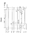
- Fig. 5 is a partial timing chart showing an example of driving method of the present embodiment, according to the driving method shown in Fig. 3A.
- the vertical scanning circuit 103 shifts the pulse ⁇ v1 alone to the high level to turn on the switch SW1. Also the pulse ⁇ t is shifted to the high level to turn on the transistors Qa1 - Qan.
- the pulse ⁇ pd is shifted to a positive potential during a period T1 to apply, through the switch SW1, a positive voltage to the electrodes 101 of the cells S11 - S1 n of the first line, whereby a reading operation is conducted in the first line and the read-out signals of the first line are accumulated, respectively through the vertical lines L1 - Ln and the transistors Qa1 - Qan, in the capacitors C1 - Cn.
- the pulse ⁇ pt is shifted to the low level to turn off the transistors Qa1 Qan.
- the horizontal scanning circuit 105 releases the pulses ⁇ h1 - ⁇ phn in succession, whereby the readout signals accumulated in the capacitors C1 - Cn are taken out in succession to the output line 104, and serially released to the outside as an output signal Vout through the amplifier 106.
- the pulse (prh is shifted to the high level to turn on the transistor Qrh, thereby eliminating the carriers in the output line 104.
- the pulse ⁇ pr is shifted to the high level to turn on the transistors Qb1 - Qbn, thereby brounding the vertical lines L1 - Ln.
- the pulse (pd is shifted to a negative potential in the period T2, thereby turning on the MOS transistors Tr of the first line.
- the p-type base areas 4 of the cells S11 - S1 n are uniformly shifted to the ground potential as explained before, then returns to the initial negative potential by the refreshing operation in the periods T3 and T4, and start the accumulating operation.
- the pulse ⁇ v1 is shifted to the low level to turn off the switch SW1.
- the pulse (pt is shifted to the high level to turn on the transistors Qa1 - Qan, thereby eliminating the carriers remaining in the capacitors C1 - Cn, through the vertical lines L1 - Ln and the transistors Qa1 - Qan.
- the refreshing operation is conducted in the periods T3 and T4 after the base potential of the cells of different lines is brought to a constant value in the period T2, so that there can be obtained an image sensor device with satisfactory retentive image characteristic and satisfactorily linear photoelectric conversion characteristic.
- the structure, not requiring the separating areas in the direction of lines, is suitable for miniaturi zation of the cells, and is easily capable of achieving a high resolution.
- the photoelectric conversion apparatus of the foregoing embodiments have, as explained above, gate-insulated transistors each having main electrodes composed of the semiconductor areas of neighboring cells, and are capable of shifting the semiconductor areas of said cells easily to a constant potential regardless of the amount of accumulated carriers, by turning on said gate-insulated transistors, thereby resolving the drawback of retentive image and improving the linearity of the photoelectric conversion characteristic.
- the photoelectric conversion cells can be electrically separated with the conventional separating areas by turning off said gate-insulated transistors.
- the structure can therefore simplify the manufacturing process, and is suitable for the miniaturization of the device.
- Fig. 7A is a schematic plan view of a third embodiment of the electrode pattern of the photoelectric conversion apparatus of the present invention
- Figs. 7B and 7C are respectively cross-sectional views thereof along a line I - I and a line II - II.
- same components as those in Figs. 1 to 6 are represented by same numbers.
- an n--type layer 3 consti tuting a collector area is formed by epitaxial growth on an n-type silicon substrate 1, and p-type base areas 4 and n+-type emitter areas 5 are formed therein to constitute bipolar transistors.
- the p-type base areas 4 are two-dimensionally arranged as shown in Fig. 7A, and the cells in the horizontal line are separated from those in the upper and lower lines by separating areas, which are composed, as shown in Fig. 7C, of an oxide film 6' formed by LOCOS oxidation and an n+-type area 108 formed thereunder.
- a gate electrode 101 is formed on an oxide film 6 as shown in Fig. 7B. Consequently a p-channel MOS transistor is formed, with the source and drain composed of the neighboring p-type base areas 4.
- Said MOS transistor being of normally-off type, is turned off when the gate electrode 101 is at the ground potential or a positive potential, thereby electrically separating the p-type base areas of the neighboring cells.
- the gate electrode 101 is given a negative potential exceeding a threshold value Vth, said transistor is turned on to mutually connect the p-type base areas 4 of the cells.
- the gate electrodes 101 are commonly connected, in the unit of each line, to a driving line 101", to which likewise connected are capacitor electrodes 101' for controlling the potential of the p-type base areas 4.
- the driving line 101" extends horizontally over the oxide film 6' constituting the separating areas.
- emitter electrodes 8 which are connected, column by column, to vertical lines 8'.
- a collector electrode 12 is formed on the bottom face of the substrate 1, across an ohmic contact layer.
- the area sensor of the present embodiment does not require particular wirings for complete refreshing.
- the area sensor requires, for driving, a vertical scanning pulse (pd and a resetting pulse cpr.
- the common connection of the gate electrodes and the capacitor electrodes enables to achieve a high speed operation with a limited number of driving pulses.
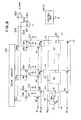
- Fig. 8 is a circuit diagram of a fourth embodiment of the photoelectric conversion apparatus of the present invention.
- the emitter electrodes 8 of cells S1 - Sn of the apparatus are respectively connected to vertical lines Ll - Ln which are respectively grounded through transistors Qr.
- Each of the vertical lines L1 - Ln is connected, respectively through transistors Qt1 and Qt2, to accumulating capacitors Ct1, Ct2, which are respectively connected, through transistors Qh1, Qh2, to output lines 203, 204.
- the gate electrodes of the transistors Qr receive a pulse (pr, while the gate electrodes of the transistors Qt1, Qt2 respective receive pulses ⁇ t1, (pt2, and the gate electrodes of the transistors Qh1, Qh2 receive scanning pulses ⁇ h1, (ph2 from a scanning circuit 201.
- the output lines 203, 204 are connected to a differential amplifier 202, and are grounded respectively through transistors Qrh1, Qrh2 receiving a resetting pulse ⁇ rh at the gate electrodes thereof. Said pulses ⁇ are released by a control unit 107 - 2. Now reference is made to a timing chart in Fig. 9 for explaining the function of the above-explained photoelectric conversion device.
- the transistors Qt1 Qr are turned on by the pulses ⁇ t1, ⁇ r in a period T1 to discharge the capacitors Ct1 to the ground potential.
- the pulse ⁇ d is supplied to the horizontal line HL while the transistors Qt1 are turned on to bias the transistors of the photoelectric conversion cells S1 - Sn in the forward direction, whereby the read-out signals are accumulated in the capacitors Ct1 (period T2).
- the cells S1 - Sn are refreshed by turning on the transistors Qr with the pulse ⁇ r while the pulse (pd is applied.
- the transistors Qt2 are turned on by the pulse (pt2 to discharge the capacitors Ct2 to the ground potential (period T3).
- the transistors Qr Upon completion of the refreshing operation, the transistors Qr are turned off by the pulse or while the pulses ⁇ d and (pt2 are applied, whereby the signals remaining in the cells S1 - Sn after refreshing are accumulated in the capacitors Ct2 (period T4).
- the scanning circuit 201 supplies the pulse ⁇ h1 to the gate electrodes of the transistors Qh1, Qh2, whereby the read-out signal and the retentive signal of the cell S11, respectively accumulated in the capacitors Ct1, Ct2 appear on the output lines 203, 204 and are processed by the differential amplifier 202.
- the read-out signal appearing on the output line 203 contains unnecessary signals which however are removed in the process by the differential amplifier.
- the resetting pulse ⁇ rh turns on the transistors Qrh1, Qrh2 to eliminate the charges remaining on the output lines 203, 204.
- the pulses ⁇ h2 - (phn) cause the read-out signals and retentive signals of the cells S2 - Sn to be transferred from the capacitors Ct1, Ct2 to the output lines 203, 204, whereby output signals Sout are obtained in succession from the differential amplifier 202.
- the pulse (pr turns on the transistors Qr to ground the emitter electrodes 8 of the cells S1 - Sn, and the pulse ⁇ d is shifted to a negative potential to turn on the MOS transistors Tr, thereby connecting the base areas of all the cells.
- the base areas of the cells are uniformly brought to the ground potential regardless of the accumulated potentials thereof (period T5).
- the refreshing operation is conducted by the shift of the pulse ⁇ d to a positive potential, and the base potential returns to the initial negative state at the end of said pulse (period T7).
- the present embodiment in which the refreshing operation is conducted in the periods T5 to T7 in addition to the period T3, can achieve further elimination of the retentive image and unnecessary signals, thereby providing an output signal of a high S/N ratio.
- a photoelectric conversion apparatus in order to completely eliminate the retentive image and unnecessary signals and to obtain an output signal of a high S/N ratio, it is necessary to sufficiently conduct the refreshing operations before and after reading the retentive image signal. Also in the above-explained apparatus it is desirable to conduct a refreshing operation in the periods T5 to T7 before the reading of the retentive image signal, but an excessively long refreshing period before reading the retentive signal is not desirable. Particularly when the apparatus is to be used as an area sensor for a video camera, the refreshing operation requires a horizontal scanning period, so that the read-out signal has to be delayed by said period. For this purpose a corresponding memory capacity has to be formed in the chip of the device, thus inevitably increasing the size of the chip.
- the aforementioned driving method has a room for improvement in order to increase the correlation between the unnecessary signal and the retentive signal contained in the read-out signal, thereby further improving the S/N ratio.
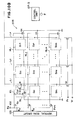
- Fig. 10 is a circuit diagram of a fifth embodiment of the present invention, wherein same components as those in Fig. 8 are represented by same numbers.
- an area sensor of m x n pixels composed of m lines of photoelectric conversion cells S1 - Sn as shown in Fig. 8.
- each of horizontal lines HL1 - HLm electrodes 101 of the cells and the gate electrode of a transistor Qx are connected, through a transistor Qv, to a terminal 102 receiving a driving pulse cpd.
- the gate electrodes of said transistors Qv of the horizontal lines HL1 - HLm are respectively connected to output terminals of a vertical scanning circuit 103, thus receiving vertical scanning pulses ⁇ v1 - cpvm.
- Said vertical scanning circuit 103 and the transistors Qv of the horizontal lines constitute a vertical scanning unit.
- the emitter electrodes 8 of the cells are connected, column by column, to vertical lines L1 - Ln, which are connected, respectively through transistors Qr, to a power source Vr.
- a photosensor unit 206 is composed of said transistors Qr, cells S11 - Smn, and transistors Qx connected to the horizontal lines.
- each of the vertical lines L1 - Ln is connected, respectively through transistors Qt1, Qt2, to capacitors Ct1, Ct2, which are respectively connected to output lines 203, 204 through transistors Qh1, Qh2.
- the gate electrodes of the transistors Qh1, Qh2 of the vertical lines Ll - Ln respectively receive horizontal scanning pulses ⁇ h1 - (phn from a horizontal scanning circuit 105.
- the output lines 203, 204 are connected to a differential amplifier 202, and are respectively connected, through transistors Qrh1, Qrh2, to the ground and to a power source Vrh2.
- the remaining structure is same as that shown in Fig. 8.
- the above-mentioned various pulses ⁇ are supplied by a control unit 107 - 3.
- Fig. 11 only shows the function of a first horizontal line HL1.
- 1H indicates the horizontal scanning period of a television signal, and a period T5 corresponds to the effective scanning period thereof.
- the vertical scanning circuit 103 releases the scanning pulse ⁇ v1 for a period 1H, thereby turning on the transistor Qv of the first horizontal line HL1.
- the transistors Qt1 and Qr are turned on by the pulses ⁇ t1, ⁇ r to discharge the capacitors Ct1 to the potential V A of the power source Vr (period T1). Then the pulse ⁇ d is applied while the transistors Qt1 are turned on to bias the cells S11 - S1n in the forward direction, whereby the read-out signals are stored in the capacitors Ct1 (period T2).
- the transistors Qt1 are turned off while the pulse ⁇ d is supplied, and the transistors Qr are turned on by the pulse ⁇ r. If the potential of the power source Vr is reduced from V A to V B (V B ⁇ V A ), the cells S11 - S1 are subject ed to a transient refreshing under a deeper forward biasing than in the period T2. Also the transistors Qt2 are turned on by the pulse ⁇ t2 to discharge the capacitors Ct2 to the potential V B of the power source Vr (period T3).
- the operations in the subsequent periods T4 - T7 are same as those shown in Fig. 9.
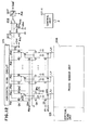
- Fig. 12 is a circuit diagram of a sixth embodiment of the present invention, wherein the vertical scanning unit and the photosensor unit 206 are omitted as they are same as those in Fig. 10.
- a buffer amplifier 205 consisting of a bipolar transistor, for preventing the level loss of the signals of the capacitors Ct1, Ct2 caused by the line capacitances Ch1, Ch2 when said signals are read to the lines 203, 204, and for enabling a high-speed scanning.
- the base electrode of the amplifier 205 is commonly connected to the transistors Qh1, Qh2 and is grounded through a transistor Qbc driven by a pulse (pbc.
- the emitter of said amplifier is connected, respectively through second scanning transistors Qh1', Qh2', to the output lines 203, 204.
- Said transistors Qh1', Qh2' are driven, together with the transistors Qh1, Qh2, by two-phase horizontal scanning pulses ⁇ a ( ⁇ 1 - ⁇ an) and ⁇ b ( ⁇ b1 - ⁇ bn).
- the collector of said amplifier receives a constant positive voltage.
- the output lines 203, 204 are respectively connected to the ground and to a power source Vrh2, respectively through transistors Qrh1, Qrh2, of which gate electrodes respectively receive resetting pulses ⁇ rh1, (prh2.
- the output terminal of the differential amplifier 202 is connected to a sample hold circuit 207 for sampling the input signal in response to a pulse ⁇ sh.
- the remaining structure is same as that shown in Fig. 10.
- the various pulses p are supplied by a control unit 107 - 4.
- the first pulse ⁇ a1 of said two-phase scanning pulses turns on the transistors Qh1 and Qh1', whereby the read-out signal accumulated in the capacitor Ct1 is supplied to the output line 203 and accumulated in the line capacitance Ch1.
- the pulse (pbc turns on the transistor Qbc, thereby dissipating the charges remaining in the capacitor Ct1 and the base electrode of the amplifier 205.
- the signal accumulated in the line 203 remains unchanged since, in this state, the amplifier 205 is inversely biased and is therefore non-conductive.
- the pulse ⁇ rh2 turns on the transistor Qrh2, thereby clearing the output line 204 to the potential Vrh2.
- Vrh2 is selected equal to -(V A - V B ), in order to have a constant bias for the amplifier 205, in releasing the readout signal of the capacitor Ct1 to the output line 203 and in releasing the readout signal of the capacitor Ct2 to the output line 204. Then, at a time tss, the second pulse ⁇ b1 of the two-phase scanning pulses turns on the transistors Qh2 and Qh2', whereby the retentive signal accumulated in the capacitor Ct2 is released to the output line 203 and accumulated in the line capacitance Ch2. Consequently the differential amplifier 202 receives the signals accumulated in the capacitors Ct1 and Ct2, and the output signal Sout of said amplifier is sampled in the sample hold circuit 206 by theinstalle ⁇ sh and released as an output signal Sout'.
- the pulse cpbc turns on the transistor Qbc to dissipate the charges remaining in the capacitor Ct2 and the base electrode of the amplifier 205. Also the pulse ⁇ rh1 turns on the transistor Qrh1, thereby clearing the output 203 to the ground potential.
- the presence of buffer amplifiers enable direct driving of the output lines and a high-speed transfer of the signals without level loss.
- the photoelectric conversion elements are composed of gate-separated sensors, but they can also be composed of elements of base accumulation type as disclosed in the Japanese Laid-open Patent Gazette No. 12759/1985. In such case it is desirable to apply a deep forward bias to the elements by increasing the potential of the pulse cprc in the period T3 for transient refreshing.
- the fifth and sixth embodiments of the present invention explained above are capable of providing an output signal of a high S/N ratio through a simple method of eliminating the dark signal and unnecessary signal such as driving noises of the photoelectric conversion elements from the read-out signal by subtracting the retentive signal after refreshing from the read-out signal of the photoelectric conversion elements, and of eliminating the retentive image component and unnecessary com ponents in a short period by applying a deeper forward bias to said elements in the refreshing operation than in other process steps.
- Fig. 14A is an equivalent circuit diagram of a seventh embodiment of the present invention
- Fig. 14B is a timing chart showing the function thereof.
- the function of the present embodiment basically consists of the steps of accumulation, reading and refreshing as explained in relation to Fig. 3.
- the driving line 102 has to be given pulses cpd for example of ⁇ 5V. Consequently, the vertical shift register in an area sensor has to withstand a voltage swing of ⁇ 10 V.
- the use of a thicker insulating film for withstanding inevitably increases the circuit area of said shift register.
- a shift register with a boost trap capacity requires a larger area in order to compensate the loss in capacity caused by the use of a thicker insulating film.
- the electrode 101' of a capacitor Cox is connected to a driving line 215 receiving a pulse ⁇ d1, which is used for effecting the reading operation by applying a positive voltage to the capacitor Cox as explained before.
- the gate electrode 101 of a MOS transistor Qr is connected to a driving line 101" receiving a negative voltage pulse ⁇ pd2, which is for on/off control of the p-channel MOS transistor Qr and for resetting each p-type base area 4 to a constant potential in the refreshing operation, as explained before.
- the reading operation is conducted by applying a positive voltage pulse ⁇ d1 to the driving line 215 as shown in Fig. 14B.
- Said positive voltage pulse ⁇ d1 elevates the potential of the P-type base area 4, thereby applying a forward bias between the base and the emitter and releasing the accumulated voltage to a vertical line 8' through the emitter electrode 8, thus obtaining a read-out signal S.
- the threshold voltage Vth of said p-channel MOS transistor Qr is so determined that it is turned off with a gate potential of 0V.
- the refreshing operation is conducted in the following manner.
- a pulse (pvc turns on the transistor Qvc, thereby grounding the vertical line 8' and eliminating the retentive charge.
- the p-channel MOS transistor Qr is turned on by a negative voltage pulse ⁇ pd2, thereby completely refreshing the p-type base area 4.
- the p-type base areas 4 Upon completion of the refreshing operation, the p-type base areas 4 return to the initial potential and start an accumulating operation for accumulating the photoexcited carriers. Thereafter the photoelectric converted signals are obtained through repeated cycles of reading, refreshing and accumulation.
- Fig. 15 is a schematic plan view of a seventh embodiment of the present invention, wherein components corresponding to those in Fig. 7A are represented by same numbers.
- the driving line 215 for applying the pulse ⁇ d1 and the vertical lines 8' are composed of aluminum, while the driving line 101" for applying the pulse (pd2 and the gate electrodes 101 are composed of polysilicon.
- Fig. 16 is a schematic plan view of an eighth embodiment of the present invention.
- the driving lines 101" and 215 are alternately provided on the separating areas, and the reading or refreshing operation is simultaneously conducted for two neighboring lines.
- This structure allows to increase the aperture ratio, since the light-receiving area is not blocked by the driving line 215 as in the case of the seventh embodiment.
- Fig. 17 is a schematic plan view of a ninth embodiment of the present invention.
- the driving lines 101" and 215 are formed in plural layers on a separating area, thus improving the aperture ratio in comparison with the seventh embodiment.
- the ninth embodiment allows signal reading of each line or interlace scanning.
- the photoelectric conversion apparatus of the seventh to ninth embodiments of the present invention is provided, as detailedly explained in the foregoing, with a first line for driving gate-insulated transistors and a second line for applying a control voltage to capacitors for controlling the potential of the semiconductor areas of the photoelectric conversion cells, so that the voltage range can be reduced in comparison with that in the conventional line for driving the photoelectric conversion cells. It is therefore rendered possible to resolve the problem of voltage resistance, and to reduce the burden of the driving system and the malfunctions. Also the circuit area, including the driving system, can be easily reduced since the insulating film need not be made thicker for withstanding a higher voltage.
Landscapes
- Engineering & Computer Science (AREA)
- Physics & Mathematics (AREA)
- Power Engineering (AREA)
- Electromagnetism (AREA)
- Condensed Matter Physics & Semiconductors (AREA)
- General Physics & Mathematics (AREA)
- Computer Hardware Design (AREA)
- Microelectronics & Electronic Packaging (AREA)
- Multimedia (AREA)
- Signal Processing (AREA)
- Transforming Light Signals Into Electric Signals (AREA)
- Solid State Image Pick-Up Elements (AREA)
Applications Claiming Priority (8)
| Application Number | Priority Date | Filing Date | Title |
|---|---|---|---|
| JP62017150A JPH084131B2 (ja) | 1987-01-29 | 1987-01-29 | 光電変換装置 |
| JP17150/87 | 1987-01-29 | ||
| JP112290/87 | 1987-05-11 | ||
| JP62112290A JPH084132B2 (ja) | 1987-05-11 | 1987-05-11 | 光電変換装置 |
| JP62123872A JP2533876B2 (ja) | 1987-05-22 | 1987-05-22 | 光電変換装置 |
| JP123872/87 | 1987-05-22 | ||
| JP126888/87 | 1987-05-26 | ||
| JP62126888A JPH07120769B2 (ja) | 1987-05-26 | 1987-05-26 | 光電変換装置 |
Publications (3)
| Publication Number | Publication Date |
|---|---|
| EP0277016A2 true EP0277016A2 (fr) | 1988-08-03 |
| EP0277016A3 EP0277016A3 (fr) | 1989-09-06 |
| EP0277016B1 EP0277016B1 (fr) | 1998-04-15 |
Family
ID=27456723
Family Applications (1)
| Application Number | Title | Priority Date | Filing Date |
|---|---|---|---|
| EP88300725A Expired - Lifetime EP0277016B1 (fr) | 1987-01-29 | 1988-01-28 | Dispositif de conversion photovoltaique |
Country Status (3)
| Country | Link |
|---|---|
| US (2) | US4962412A (fr) |
| EP (1) | EP0277016B1 (fr) |
| DE (1) | DE3856165T2 (fr) |
Cited By (14)
| Publication number | Priority date | Publication date | Assignee | Title |
|---|---|---|---|---|
| EP0434215A2 (fr) * | 1989-11-21 | 1991-06-26 | Canon Kabushiki Kaisha | Dispositif de conversion à électrode photosensible comprenant une structure d'électrode de commande et appareil equipé de ce dispositif |
| EP0437633A1 (fr) * | 1989-08-04 | 1991-07-24 | Canon Kabushiki Kaisha | Convertisseur photoelectrique |
| EP0473294A1 (fr) * | 1990-08-07 | 1992-03-04 | Canon Kabushiki Kaisha | Dispositif de photo conversion |
| EP0488174A2 (fr) * | 1990-11-27 | 1992-06-03 | Canon Kabushiki Kaisha | Dispositif de conversion photo-électrique et appareil de traitement de l'information utilisant ce dispositif |
| EP0495414A1 (fr) * | 1991-01-11 | 1992-07-22 | Canon Kabushiki Kaisha | Dispositif de conversion photo-électrique et appareil de traitement d'image utilisant ce dispositif |
| US5241169A (en) * | 1989-11-21 | 1993-08-31 | Canon Kabushiki Kaisha | Photoelectric conversion device having an improved control electrode structure and apparatus equipped with same |
| EP0559207A1 (fr) * | 1992-03-06 | 1993-09-08 | Canon Kabushiki Kaisha | Dispositif de conversion photoélectrique |
| US5260560A (en) * | 1990-03-02 | 1993-11-09 | Canon Kabushiki Kaisha | Photoelectric transfer device |
| US5272345A (en) * | 1989-09-22 | 1993-12-21 | Ada Technologies, Inc. | Calibration method and apparatus for measuring the concentration of components in a fluid |
| EP0576022A1 (fr) * | 1992-06-25 | 1993-12-29 | Canon Kabushiki Kaisha | Dispositif de conversion photo-électrique et son procédé de commande |
| US5288988A (en) * | 1990-08-07 | 1994-02-22 | Canon Kabushiki Kaisha | Photoconversion device having reset control circuitry |
| EP0665685A2 (fr) * | 1994-01-31 | 1995-08-02 | Sony Corporation | Capteur d'image à l'état solide avec phototransistors à effet de champ et condensateurs de stockage |
| US5723877A (en) * | 1989-08-04 | 1998-03-03 | Canon Kabushiki Kaisha | Photoelectric conversion apparatus |
| EP1267411A2 (fr) * | 2001-06-07 | 2002-12-18 | Canon Kabushiki Kaisha | Dispositif de prise de vues d'images radiologiques et sa méthode de commande |
Families Citing this family (48)
| Publication number | Priority date | Publication date | Assignee | Title |
|---|---|---|---|---|
| JPH07120770B2 (ja) * | 1987-07-03 | 1995-12-20 | キヤノン株式会社 | 光電変換装置 |
| US5172249A (en) * | 1989-05-31 | 1992-12-15 | Canon Kabushiki Kaisha | Photoelectric converting apparatus with improved switching to reduce sensor noises |
| US5028788A (en) * | 1990-04-03 | 1991-07-02 | Electromed International Ltd. | X-ray sensor array |
| JPH0828497B2 (ja) * | 1990-07-19 | 1996-03-21 | 株式会社東芝 | 固体撮像装置 |
| JP2765635B2 (ja) * | 1991-01-11 | 1998-06-18 | キヤノン株式会社 | 光電変換装置 |
| JPH04261071A (ja) * | 1991-01-11 | 1992-09-17 | Canon Inc | 光電変換装置 |
| US5401952A (en) * | 1991-10-25 | 1995-03-28 | Canon Kabushiki Kaisha | Signal processor having avalanche photodiodes |
| JPH05335615A (ja) * | 1992-05-27 | 1993-12-17 | Canon Inc | 光電変換装置 |
| US5453611A (en) * | 1993-01-01 | 1995-09-26 | Canon Kabushiki Kaisha | Solid-state image pickup device with a plurality of photoelectric conversion elements on a common semiconductor chip |
| JP2703167B2 (ja) * | 1993-08-06 | 1998-01-26 | 株式会社日立製作所 | 受光素子及びその製造方法 |
| JP3467858B2 (ja) * | 1993-11-02 | 2003-11-17 | ソニー株式会社 | 光電変換素子 |
| JP3432051B2 (ja) * | 1995-08-02 | 2003-07-28 | キヤノン株式会社 | 光電変換装置 |
| US5844265A (en) * | 1996-07-11 | 1998-12-01 | Synaptics, Incorporated | Sense amplifier for high-density imaging array |
| US5838176A (en) * | 1996-07-11 | 1998-11-17 | Foveonics, Inc. | Correlated double sampling circuit |
| TW421962B (en) | 1997-09-29 | 2001-02-11 | Canon Kk | Image sensing device using mos type image sensing elements |
| DE60044836D1 (de) | 1999-10-05 | 2010-09-30 | Canon Kk | Festkörperbildaufnahmevorrichtung und Bildaufnahmesystem |
| JP3467013B2 (ja) | 1999-12-06 | 2003-11-17 | キヤノン株式会社 | 固体撮像装置 |
| JP3647390B2 (ja) | 2000-06-08 | 2005-05-11 | キヤノン株式会社 | 電荷転送装置、固体撮像装置及び撮像システム |
| WO2002027763A2 (fr) | 2000-09-25 | 2002-04-04 | Foveon, Inc. | Detecteur actif de pixels a annulation du bruit |
| CN1225897C (zh) * | 2002-08-21 | 2005-11-02 | 佳能株式会社 | 摄像装置 |
| JP4383959B2 (ja) | 2003-05-28 | 2009-12-16 | キヤノン株式会社 | 光電変換装置およびその製造方法 |
| JP2005328275A (ja) * | 2004-05-13 | 2005-11-24 | Canon Inc | 固体撮像装置および撮像システム |
| US7592645B2 (en) | 2004-12-08 | 2009-09-22 | Canon Kabushiki Kaisha | Photoelectric conversion device and method for producing photoelectric conversion device |
| JP4618786B2 (ja) * | 2005-01-28 | 2011-01-26 | キヤノン株式会社 | 固体撮像装置の製造方法 |
| US7884434B2 (en) * | 2005-12-19 | 2011-02-08 | Canon Kabushiki Kaisha | Photoelectric conversion apparatus, producing method therefor, image pickup module and image pickup system |
| JP5188080B2 (ja) * | 2007-03-06 | 2013-04-24 | キヤノン株式会社 | 撮像装置、撮像装置の駆動方法、及び読み出し装置 |
| JP5063234B2 (ja) * | 2007-07-20 | 2012-10-31 | キヤノン株式会社 | 撮像装置、撮像システム、及び、撮像装置の動作方法 |
| JP5288823B2 (ja) * | 2008-02-18 | 2013-09-11 | キヤノン株式会社 | 光電変換装置、及び光電変換装置の製造方法 |
| JP5188221B2 (ja) | 2008-03-14 | 2013-04-24 | キヤノン株式会社 | 固体撮像装置 |
| JP5188292B2 (ja) * | 2008-06-30 | 2013-04-24 | キヤノン株式会社 | 撮像システムおよび撮像システムの駆動方法 |
| JP2010016056A (ja) | 2008-07-01 | 2010-01-21 | Canon Inc | 光電変換装置 |
| JP5661260B2 (ja) * | 2009-07-16 | 2015-01-28 | キヤノン株式会社 | 固体撮像装置及びその駆動方法 |
| JP5489570B2 (ja) | 2009-07-27 | 2014-05-14 | キヤノン株式会社 | 光電変換装置及び撮像システム |
| JP5676945B2 (ja) | 2010-07-08 | 2015-02-25 | キヤノン株式会社 | 電子装置、電子装置の素子分離方法、電子装置の製造方法、及び電子装置を備えた表示装置 |
| JP5610961B2 (ja) | 2010-09-30 | 2014-10-22 | キヤノン株式会社 | 固体撮像装置及び固体撮像装置の駆動方法 |
| JP5767465B2 (ja) | 2010-12-15 | 2015-08-19 | キヤノン株式会社 | 固体撮像装置およびその製造方法ならびにカメラ |
| JP5893550B2 (ja) | 2012-04-12 | 2016-03-23 | キヤノン株式会社 | 撮像装置及び撮像システム |
| JP2015177034A (ja) | 2014-03-14 | 2015-10-05 | キヤノン株式会社 | 固体撮像装置、その製造方法、及びカメラ |
| JP6389685B2 (ja) | 2014-07-30 | 2018-09-12 | キヤノン株式会社 | 撮像装置、および、撮像システム |
| JP6835090B2 (ja) * | 2016-07-29 | 2021-02-24 | ソニー株式会社 | 表示装置、表示装置の製造方法、及び、電子機器 |
| JP6552479B2 (ja) | 2016-12-28 | 2019-07-31 | キヤノン株式会社 | 固体撮像装置及び撮像システム |
| JP6953263B2 (ja) | 2017-10-05 | 2021-10-27 | キヤノン株式会社 | 固体撮像装置および撮像システム |
| JP7108421B2 (ja) | 2018-02-15 | 2022-07-28 | キヤノン株式会社 | 撮像装置及び撮像システム |
| JP7134781B2 (ja) | 2018-08-17 | 2022-09-12 | キヤノン株式会社 | 光電変換装置及び撮像システム |
| US11503234B2 (en) | 2019-02-27 | 2022-11-15 | Canon Kabushiki Kaisha | Photoelectric conversion device, imaging system, radioactive ray imaging system, and movable object |
| JP2021019058A (ja) | 2019-07-18 | 2021-02-15 | キヤノン株式会社 | 光電変換装置および機器 |
| JP2022025594A (ja) | 2020-07-29 | 2022-02-10 | キヤノン株式会社 | 光電変換装置 |
| JP2022052529A (ja) | 2020-09-23 | 2022-04-04 | キヤノン株式会社 | 光電変換装置、撮像装置、半導体装置及び光電変換システム |
Citations (2)
| Publication number | Priority date | Publication date | Assignee | Title |
|---|---|---|---|---|
| DE3529025A1 (de) * | 1984-08-15 | 1986-02-27 | Olympus Optical Co., Ltd., Tokio/Tokyo | Festkoerper-bildsensor |
| US4712138A (en) * | 1984-12-28 | 1987-12-08 | Canon Kabushiki Kaisha | Low-noise apparatus for image pickup and combination of light and electric signals |
Family Cites Families (10)
| Publication number | Priority date | Publication date | Assignee | Title |
|---|---|---|---|---|
| US4117514A (en) * | 1977-02-14 | 1978-09-26 | Matsushita Electric Industrial Co., Ltd. | Solid state imaging device |
| JPS5738073A (en) * | 1980-08-20 | 1982-03-02 | Hitachi Ltd | Solid-state image sensor |
| JPS58169965A (ja) * | 1982-03-31 | 1983-10-06 | Hitachi Ltd | 固体撮像装置 |
| US4686554A (en) * | 1983-07-02 | 1987-08-11 | Canon Kabushiki Kaisha | Photoelectric converter |
| JPS6030282A (ja) * | 1983-07-28 | 1985-02-15 | Mitsubishi Electric Corp | 固体撮像装置 |
| JPS6032486A (ja) * | 1983-08-03 | 1985-02-19 | Hitachi Ltd | 電荷転送型固体撮像素子 |
| JPS60120556A (ja) * | 1983-12-02 | 1985-06-28 | Hitachi Ltd | 固体撮像装置 |
| JPS60120555A (ja) * | 1983-12-02 | 1985-06-28 | Hitachi Ltd | 固体撮像装置 |
| JPH0719882B2 (ja) * | 1985-05-01 | 1995-03-06 | キヤノン株式会社 | 光電変換装置 |
| JPH0760888B2 (ja) * | 1985-06-12 | 1995-06-28 | キヤノン株式会社 | 光電変換装置 |
-
1988
- 1988-01-28 EP EP88300725A patent/EP0277016B1/fr not_active Expired - Lifetime
- 1988-01-28 DE DE3856165T patent/DE3856165T2/de not_active Expired - Fee Related
-
1990
- 1990-01-29 US US07/470,407 patent/US4962412A/en not_active Expired - Lifetime
- 1990-07-05 US US07/548,508 patent/US5060042A/en not_active Expired - Lifetime
Patent Citations (2)
| Publication number | Priority date | Publication date | Assignee | Title |
|---|---|---|---|---|
| DE3529025A1 (de) * | 1984-08-15 | 1986-02-27 | Olympus Optical Co., Ltd., Tokio/Tokyo | Festkoerper-bildsensor |
| US4712138A (en) * | 1984-12-28 | 1987-12-08 | Canon Kabushiki Kaisha | Low-noise apparatus for image pickup and combination of light and electric signals |
Non-Patent Citations (1)
| Title |
|---|
| IEEE TRANSACTIONS ON ELECTRON DEVICES. vol. ED-26, no. 12, December 1979, New York, pages 1970-1977; J.-I. NISHIZAWA et al.: "Static induction transistor image sensors". * |
Cited By (26)
| Publication number | Priority date | Publication date | Assignee | Title |
|---|---|---|---|---|
| EP0437633A1 (fr) * | 1989-08-04 | 1991-07-24 | Canon Kabushiki Kaisha | Convertisseur photoelectrique |
| US6127692A (en) * | 1989-08-04 | 2000-10-03 | Canon Kabushiki Kaisha | Photoelectric conversion apparatus |
| US5723877A (en) * | 1989-08-04 | 1998-03-03 | Canon Kabushiki Kaisha | Photoelectric conversion apparatus |
| EP0437633A4 (en) * | 1989-08-04 | 1992-09-23 | Canon Kabushiki Kaisha | Photo-electric converter |
| US5272345A (en) * | 1989-09-22 | 1993-12-21 | Ada Technologies, Inc. | Calibration method and apparatus for measuring the concentration of components in a fluid |
| EP0434215A3 (en) * | 1989-11-21 | 1992-01-15 | Canon Kabushiki Kaisha | Photoelectrode conversion device having a control electrode structure and apparatus equipped with the same |
| US5124544A (en) * | 1989-11-21 | 1992-06-23 | Canon Kabushiki Kaisha | Photoelectric conversion device having an improved control electrode structure and apparatus equipped with same |
| EP0434215A2 (fr) * | 1989-11-21 | 1991-06-26 | Canon Kabushiki Kaisha | Dispositif de conversion à électrode photosensible comprenant une structure d'électrode de commande et appareil equipé de ce dispositif |
| US5241169A (en) * | 1989-11-21 | 1993-08-31 | Canon Kabushiki Kaisha | Photoelectric conversion device having an improved control electrode structure and apparatus equipped with same |
| US5260560A (en) * | 1990-03-02 | 1993-11-09 | Canon Kabushiki Kaisha | Photoelectric transfer device |
| US5424529A (en) * | 1990-08-07 | 1995-06-13 | Canon Kabushiki Kaisha | Photoconversion device including reset means and biasing means |
| EP0473294A1 (fr) * | 1990-08-07 | 1992-03-04 | Canon Kabushiki Kaisha | Dispositif de photo conversion |
| US5288988A (en) * | 1990-08-07 | 1994-02-22 | Canon Kabushiki Kaisha | Photoconversion device having reset control circuitry |
| EP0488174A3 (en) * | 1990-11-27 | 1992-12-23 | Canon Kabushiki Kaisha | Photoelectric converting device and information processing apparatus employing the same |
| US5283428A (en) * | 1990-11-27 | 1994-02-01 | Canon Kabushiki Kaisha | Photoelectric converting device and information processing apparatus employing the same |
| EP0488174A2 (fr) * | 1990-11-27 | 1992-06-03 | Canon Kabushiki Kaisha | Dispositif de conversion photo-électrique et appareil de traitement de l'information utilisant ce dispositif |
| EP0495414A1 (fr) * | 1991-01-11 | 1992-07-22 | Canon Kabushiki Kaisha | Dispositif de conversion photo-électrique et appareil de traitement d'image utilisant ce dispositif |
| US5406332A (en) * | 1992-03-06 | 1995-04-11 | Canon Kabushiki Kaisha | Photoelectric converting device |
| EP0559207A1 (fr) * | 1992-03-06 | 1993-09-08 | Canon Kabushiki Kaisha | Dispositif de conversion photoélectrique |
| US5386108A (en) * | 1992-06-25 | 1995-01-31 | Canon Kabushiki Kaisha | Photoelectric conversion device for amplifying and outputting photoelectrically converted signal, and a method thereof |
| EP0576022A1 (fr) * | 1992-06-25 | 1993-12-29 | Canon Kabushiki Kaisha | Dispositif de conversion photo-électrique et son procédé de commande |
| EP0665685A2 (fr) * | 1994-01-31 | 1995-08-02 | Sony Corporation | Capteur d'image à l'état solide avec phototransistors à effet de champ et condensateurs de stockage |
| EP0665685A3 (fr) * | 1994-01-31 | 1996-02-07 | Sony Corp | Capteur d'image à l'état solide avec phototransistors à effet de champ et condensateurs de stockage. |
| US5808677A (en) * | 1994-01-31 | 1998-09-15 | Sony Corporation | Solid-state imaging device having a reset switch for resetting potential of capacitor |
| EP1267411A2 (fr) * | 2001-06-07 | 2002-12-18 | Canon Kabushiki Kaisha | Dispositif de prise de vues d'images radiologiques et sa méthode de commande |
| EP1267411A3 (fr) * | 2001-06-07 | 2006-01-18 | Canon Kabushiki Kaisha | Dispositif de prise de vues d'images radiologiques et sa méthode de commande |
Also Published As
| Publication number | Publication date |
|---|---|
| EP0277016B1 (fr) | 1998-04-15 |
| DE3856165D1 (de) | 1998-05-20 |
| EP0277016A3 (fr) | 1989-09-06 |
| US4962412A (en) | 1990-10-09 |
| US5060042A (en) | 1991-10-22 |
| DE3856165T2 (de) | 1998-08-27 |
Similar Documents
| Publication | Publication Date | Title |
|---|---|---|
| EP0277016A2 (fr) | Dispositif de conversion photovoltaique | |
| US5401952A (en) | Signal processor having avalanche photodiodes | |
| US7110030B1 (en) | Solid state image pickup apparatus | |
| US4835404A (en) | Photoelectric converting apparatus with a switching circuit and a resetting circuit for reading and resetting a plurality of lines sensors | |
| US6876019B2 (en) | Charge transfer apparatus | |
| US4972243A (en) | Photoelectric conversion apparatus with shielded cell | |
| US5708263A (en) | Photodetector array | |
| EP0455311B1 (fr) | Dispositif capteur d'images | |
| US5933188A (en) | Photoelectric conversion apparatus and method with reset | |
| EP0365000B1 (fr) | Senseur d'image à dispositif à couplage de charge avec drain vertical de dépassement | |
| USRE34309E (en) | Image sensor device having plural photoelectric converting elements | |
| US5274459A (en) | Solid state image sensing device with a feedback gate transistor at each photo-sensing section | |
| EP0718889A2 (fr) | Dispositif de conversion photo-électrique et méthode de fabrication | |
| US4868405A (en) | Photoelectric converting apparatus having a common region connecting either sources or drains to a common signal line | |
| EP0372456B1 (fr) | Dispositif CCD de prise de vue avec drain de dépassement vertical | |
| JPH0562869B2 (fr) | ||
| US5825056A (en) | Scanning switch transistor for solid state imaging device | |
| JPH05244513A (ja) | 光電変換装置及びその駆動方法 | |
| JP2501207B2 (ja) | 光電変換装置 | |
| JPS63128665A (ja) | 光電変換装置 | |
| JPH0736615B2 (ja) | 光電変換装置 | |
| JPH0630392B2 (ja) | 一次元半導体撮像装置 | |
| JPH09139891A (ja) | 光電変換装置およびこれを用いた固体撮像装置 | |
| JPH04369267A (ja) | 信号電荷検出回路 | |
| JPH02224480A (ja) | 固体撮像素子 |
Legal Events
| Date | Code | Title | Description |
|---|---|---|---|
| PUAI | Public reference made under article 153(3) epc to a published international application that has entered the european phase |
Free format text: ORIGINAL CODE: 0009012 |
|
| AK | Designated contracting states |
Kind code of ref document: A2 Designated state(s): DE FR GB IT NL |
|
| PUAL | Search report despatched |
Free format text: ORIGINAL CODE: 0009013 |
|
| AK | Designated contracting states |
Kind code of ref document: A3 Designated state(s): DE FR GB IT NL |
|
| RHK1 | Main classification (correction) |
Ipc: H04N 3/15 |
|
| 17P | Request for examination filed |
Effective date: 19900124 |
|
| 17Q | First examination report despatched |
Effective date: 19930616 |
|
| GRAG | Despatch of communication of intention to grant |
Free format text: ORIGINAL CODE: EPIDOS AGRA |
|
| GRAG | Despatch of communication of intention to grant |
Free format text: ORIGINAL CODE: EPIDOS AGRA |
|
| GRAG | Despatch of communication of intention to grant |
Free format text: ORIGINAL CODE: EPIDOS AGRA |
|
| GRAH | Despatch of communication of intention to grant a patent |
Free format text: ORIGINAL CODE: EPIDOS IGRA |
|
| GRAH | Despatch of communication of intention to grant a patent |
Free format text: ORIGINAL CODE: EPIDOS IGRA |
|
| GRAA | (expected) grant |
Free format text: ORIGINAL CODE: 0009210 |
|
| AK | Designated contracting states |
Kind code of ref document: B1 Designated state(s): DE FR GB IT NL |
|
| ITF | It: translation for a ep patent filed |
Owner name: SOCIETA' ITALIANA BREVETTI S.P.A. |
|
| REF | Corresponds to: |
Ref document number: 3856165 Country of ref document: DE Date of ref document: 19980520 |
|
| ET | Fr: translation filed | ||
| PLBE | No opposition filed within time limit |
Free format text: ORIGINAL CODE: 0009261 |
|
| STAA | Information on the status of an ep patent application or granted ep patent |
Free format text: STATUS: NO OPPOSITION FILED WITHIN TIME LIMIT |
|
| 26N | No opposition filed | ||
| REG | Reference to a national code |
Ref country code: GB Ref legal event code: IF02 |
|
| PGFP | Annual fee paid to national office [announced via postgrant information from national office to epo] |
Ref country code: GB Payment date: 20030114 Year of fee payment: 16 |
|
| PGFP | Annual fee paid to national office [announced via postgrant information from national office to epo] |
Ref country code: DE Payment date: 20030123 Year of fee payment: 16 |
|
| PGFP | Annual fee paid to national office [announced via postgrant information from national office to epo] |
Ref country code: FR Payment date: 20030124 Year of fee payment: 16 |
|
| PGFP | Annual fee paid to national office [announced via postgrant information from national office to epo] |
Ref country code: NL Payment date: 20030131 Year of fee payment: 16 |
|
| PG25 | Lapsed in a contracting state [announced via postgrant information from national office to epo] |
Ref country code: GB Free format text: LAPSE BECAUSE OF NON-PAYMENT OF DUE FEES Effective date: 20040128 |
|
| PG25 | Lapsed in a contracting state [announced via postgrant information from national office to epo] |
Ref country code: NL Free format text: LAPSE BECAUSE OF NON-PAYMENT OF DUE FEES Effective date: 20040801 |
|
| PG25 | Lapsed in a contracting state [announced via postgrant information from national office to epo] |
Ref country code: DE Free format text: LAPSE BECAUSE OF NON-PAYMENT OF DUE FEES Effective date: 20040803 |
|
| GBPC | Gb: european patent ceased through non-payment of renewal fee |
Effective date: 20040128 |
|
| PG25 | Lapsed in a contracting state [announced via postgrant information from national office to epo] |
Ref country code: FR Free format text: LAPSE BECAUSE OF NON-PAYMENT OF DUE FEES Effective date: 20040930 |
|
| NLV4 | Nl: lapsed or anulled due to non-payment of the annual fee |
Effective date: 20040801 |
|
| REG | Reference to a national code |
Ref country code: FR Ref legal event code: ST |
|
| PG25 | Lapsed in a contracting state [announced via postgrant information from national office to epo] |
Ref country code: IT Free format text: LAPSE BECAUSE OF NON-PAYMENT OF DUE FEES;WARNING: LAPSES OF ITALIAN PATENTS WITH EFFECTIVE DATE BEFORE 2007 MAY HAVE OCCURRED AT ANY TIME BEFORE 2007. THE CORRECT EFFECTIVE DATE MAY BE DIFFERENT FROM THE ONE RECORDED. Effective date: 20050128 |