EP0273384B1 - Optische Informationsaufzeichnungsplatte und Gerät dafür - Google Patents
Optische Informationsaufzeichnungsplatte und Gerät dafür Download PDFInfo
- Publication number
- EP0273384B1 EP0273384B1 EP87119118A EP87119118A EP0273384B1 EP 0273384 B1 EP0273384 B1 EP 0273384B1 EP 87119118 A EP87119118 A EP 87119118A EP 87119118 A EP87119118 A EP 87119118A EP 0273384 B1 EP0273384 B1 EP 0273384B1
- Authority
- EP
- European Patent Office
- Prior art keywords
- information recording
- information
- track
- tracks
- sections
- Prior art date
- Legal status (The legal status is an assumption and is not a legal conclusion. Google has not performed a legal analysis and makes no representation as to the accuracy of the status listed.)
- Expired
Links
- 230000003287 optical effect Effects 0.000 title claims description 124
- 230000015654 memory Effects 0.000 claims description 25
- 238000010586 diagram Methods 0.000 description 7
- 238000004519 manufacturing process Methods 0.000 description 5
- 238000000034 method Methods 0.000 description 5
- 230000010355 oscillation Effects 0.000 description 4
- 230000002093 peripheral effect Effects 0.000 description 3
- 238000006243 chemical reaction Methods 0.000 description 2
- 238000009825 accumulation Methods 0.000 description 1
- 238000010276 construction Methods 0.000 description 1
- 230000004044 response Effects 0.000 description 1
- 230000001360 synchronised effect Effects 0.000 description 1
Images




Classifications
-
- G—PHYSICS
- G11—INFORMATION STORAGE
- G11B—INFORMATION STORAGE BASED ON RELATIVE MOVEMENT BETWEEN RECORD CARRIER AND TRANSDUCER
- G11B7/00—Recording or reproducing by optical means, e.g. recording using a thermal beam of optical radiation by modifying optical properties or the physical structure, reproducing using an optical beam at lower power by sensing optical properties; Record carriers therefor
- G11B7/24—Record carriers characterised by shape, structure or physical properties, or by the selection of the material
- G11B7/2407—Tracks or pits; Shape, structure or physical properties thereof
- G11B7/24085—Pits
-
- G—PHYSICS
- G11—INFORMATION STORAGE
- G11B—INFORMATION STORAGE BASED ON RELATIVE MOVEMENT BETWEEN RECORD CARRIER AND TRANSDUCER
- G11B20/00—Signal processing not specific to the method of recording or reproducing; Circuits therefor
- G11B20/10—Digital recording or reproducing
-
- G—PHYSICS
- G11—INFORMATION STORAGE
- G11B—INFORMATION STORAGE BASED ON RELATIVE MOVEMENT BETWEEN RECORD CARRIER AND TRANSDUCER
- G11B27/00—Editing; Indexing; Addressing; Timing or synchronising; Monitoring; Measuring tape travel
- G11B27/10—Indexing; Addressing; Timing or synchronising; Measuring tape travel
-
- G—PHYSICS
- G11—INFORMATION STORAGE
- G11B—INFORMATION STORAGE BASED ON RELATIVE MOVEMENT BETWEEN RECORD CARRIER AND TRANSDUCER
- G11B27/00—Editing; Indexing; Addressing; Timing or synchronising; Monitoring; Measuring tape travel
- G11B27/10—Indexing; Addressing; Timing or synchronising; Measuring tape travel
- G11B27/102—Programmed access in sequence to addressed parts of tracks of operating record carriers
- G11B27/105—Programmed access in sequence to addressed parts of tracks of operating record carriers of operating discs
-
- G—PHYSICS
- G11—INFORMATION STORAGE
- G11B—INFORMATION STORAGE BASED ON RELATIVE MOVEMENT BETWEEN RECORD CARRIER AND TRANSDUCER
- G11B27/00—Editing; Indexing; Addressing; Timing or synchronising; Monitoring; Measuring tape travel
- G11B27/10—Indexing; Addressing; Timing or synchronising; Measuring tape travel
- G11B27/19—Indexing; Addressing; Timing or synchronising; Measuring tape travel by using information detectable on the record carrier
- G11B27/28—Indexing; Addressing; Timing or synchronising; Measuring tape travel by using information detectable on the record carrier by using information signals recorded by the same method as the main recording
- G11B27/30—Indexing; Addressing; Timing or synchronising; Measuring tape travel by using information detectable on the record carrier by using information signals recorded by the same method as the main recording on the same track as the main recording
- G11B27/3027—Indexing; Addressing; Timing or synchronising; Measuring tape travel by using information detectable on the record carrier by using information signals recorded by the same method as the main recording on the same track as the main recording used signal is digitally coded
-
- G—PHYSICS
- G11—INFORMATION STORAGE
- G11B—INFORMATION STORAGE BASED ON RELATIVE MOVEMENT BETWEEN RECORD CARRIER AND TRANSDUCER
- G11B7/00—Recording or reproducing by optical means, e.g. recording using a thermal beam of optical radiation by modifying optical properties or the physical structure, reproducing using an optical beam at lower power by sensing optical properties; Record carriers therefor
- G11B7/007—Arrangement of the information on the record carrier, e.g. form of tracks, actual track shape, e.g. wobbled, or cross-section, e.g. v-shaped; Sequential information structures, e.g. sectoring or header formats within a track
- G11B7/00745—Sectoring or header formats within a track
-
- G—PHYSICS
- G11—INFORMATION STORAGE
- G11B—INFORMATION STORAGE BASED ON RELATIVE MOVEMENT BETWEEN RECORD CARRIER AND TRANSDUCER
- G11B7/00—Recording or reproducing by optical means, e.g. recording using a thermal beam of optical radiation by modifying optical properties or the physical structure, reproducing using an optical beam at lower power by sensing optical properties; Record carriers therefor
- G11B7/12—Heads, e.g. forming of the optical beam spot or modulation of the optical beam
- G11B7/14—Heads, e.g. forming of the optical beam spot or modulation of the optical beam specially adapted to record on, or to reproduce from, more than one track simultaneously
-
- G—PHYSICS
- G11—INFORMATION STORAGE
- G11B—INFORMATION STORAGE BASED ON RELATIVE MOVEMENT BETWEEN RECORD CARRIER AND TRANSDUCER
- G11B2220/00—Record carriers by type
- G11B2220/20—Disc-shaped record carriers
Definitions
- optical information recording disks are attracting attention as mass capacity information media, although they are not of as large capacity as magnetic tapes.
- CLV constant linear velocity
- the disk speed needs to be changed for each access, and this results in a slower access time.
- the CAV constant angular velocity
- MCAV modified constant angular velocity
- Fig. 9 shows the recording surface of the optical information recording disk based on the conventional MCAV system.
- indicated by 66 is an optical guide groove for track 0 sector 0 on the optical information recording disk.
- Indicated by 67 is an address information recording section in the form of a small pit for track 0 sector 0, in which section are recorded address information including a sector mark, synchronizing VFO signal and track information, and information such as error check code for the address information, all recorded at manufacturing of the master disk for the optical information recording disk.
- Indicated by 68, 69, 70, 71, 72 and 73 are information recording sections for track 0 sector 1, track 0 sector 9, track 1 sector 0, track 1 sector 10, track 2 sector 0, and track 2 sector 6, respectively.
- Indicated by 74, 75 and 76 are address information sections for track 6 sector 4, track 8 sector 5, and track 9 sector 13.
- a region extending from an information recording region 66 following the address information recording section 67 for track 0 sector 0 to an information recording region following the address information recording section 73 for track 2 sector 6, and a region extending from an information recording region following the address information recording section 74 for track 8 sector 4 to an information recording region following the address information recording section 76 for track 9 sector 13 have records of different image data of the same number of pixels, and each of these regions occupies 28 sectors. Although these data are recorded dividedly in sectors with a certain information capacity for the control or management convenience, they occupy different numbers of tracks due to different numbers of division for compensating the different circumferential lengths at inner and outer portions while maintaining a virtually constant linear density.
- the worst data transfer rate through recording and reproduction is equivalently 10 sectors per disk revolution, and it is determined by the transfer rate of the innermost track.
- Fig. 10 shows a conventional MCAV optical information recording disk apparatus.
- 38 is a double-sided optical information disk
- 39 is an optical head
- 41 is a disk spindle motor
- 46 is a binary threshold circuit
- 48 is an optical head drive control circuit
- 50 is an address information detecting circuit
- 52 is a PLL circuit
- 54 is an error correcting circuit
- 56 is a buffer memory circuit
- 58 is a laser drive circuit
- 60 is a control microcomputer.
- the control microcomputer which implements head tracking on any desired track on the optical information recording disk 38, operates on the optical head drive circuit 48 to have a seek operation for the optical head 39 to the desired target track so that address information read out by the binary threshold circuit 46 and address information detecting circuit 50 matches the desired address.
- binary information from the host computer is stored in necessary quantity in a buffer memory 56, and, after being appended with error correcting codes by an error correcting circuit 54, it is written onto the optical information disk 38 by the laser drive circuit 58.
- a synthesized oscillator in the PLL circuit 52 is set up in advance by the control computer 60 to oscillate the comparing source oscillation frequency corresponding to the target track, and recorded information which was made binary by the binary threshold circuit 46 is read out in response to the reproduction clock produced by the PLL circuit and which frequency is compared with the source oscillation frequency, and, after being rendered error correction by the error correcting circuit 54, it is sent to the buffer memory circuit 56. The data in the buffer memory is then sent to the host computer.
- the data transfer rate from the host computer at recording or to the host computer at reproduction is in quantity equivalent to 18 sectors per disk revolution at the outermost portion and 10 sectors at the innermost portion.
- the conventional MCAV optical information recording disk is constant in revolution and, although the concept of "1 track" exists, it has different recording capacities at an inner portion and outer portion, and therefore the number of tracks cannot be correspondent to a certain quantity of information data and, in addition, the maximum information transfer rate is determined by the worst transfer rate of the innermost portion.
- the physical and logical tracks are desirably consistent. Therefore, the conventional arrangement has problems in software overhead to cope with the above matter and increased hardware components for the conversion table. Even though a fast, mass data transfer for digital video data might be accomplished using the outermost portion, the worst transfer rate in the innermost portion negates any improvement over the CAV system.
- the ordinary CLV system successfully overcomes the problem of transfer, however, it necessitates a very high disk revolving speed for recording the innermost portion, creating mechanical problems of vibration and increased access time due to the inertia to follow the disk speed which varies it each access operation.
- the present invention is intended to provide an optical information recording disk and optical information recording disk apparatus operative based on the concept of "tracks” and “sectors” on the recording medium as in the conventional CAV (constant angular velocity) system without sacrificing the fast-access and mass-storage capabilities of the MCAV recording system, and operative in unison with conventional computers.
- the invention is also intended to realize fast data transfer.
- the inventive optical information recording disk as defined in independant claim 1 has first information recording sections provided in a constant angular interval on spiral tracks arranged dividedly in equal number in an inner and outer portions on one side of a recording disk or on spiral tracks arranged in equal number on both sides of a recording disk, partitioned information sections divided from part or all of the first information recording sections with the length of each partitioned section being longer than a certain predetermined length and with the number of divisions per first information recording section being determined depending on the radius of track so as to have a maximum number of divisions, and address information sections on the spiral tracks for identifying the information recording position.
- Information is recorded on spiral tracks in the inner portion in the order from inside to outside, and information is recorded on spiral tracks in the outer portion, which have the different or opposite spiral direction from that in the inner portion, in the order from outside to inside.
- information is recorded on spiral tracks from inside to outside on a first surface and information is recorded on spiral tracks on a second surface, which have the same spiral direction as the first surface, in the order from outside to inside, and a series of information is recorded dividedly with the correspondence being made between the first information recording sections of a specific inner track and a specific outer track, with the specific tracks being confined to have such relation that total number of divisions per first information recording section of the inner and outer portions is equal to the total of the number of divisions of the innermost first information recording section and the number of divisions of the outermost first information recording section.
- the inventive optical information recording disk apparatus as defined in independant claim 4 includes an optical information recording disk having address information sections on tracks for identifying the information recording position and first information recording sections provided in a constant angular interval on tracks, and partitioned information sections divided from part or all of the first information recording sections, with their length being longer than a predetermined length and with their number of divisions per information recording section being determined depending on the radius of track so as to have a maximum number of divisions, at least one pair of heads for writing or reading information on the optical information recording disk, means of converting information, which has been read out of the optical information recording disk, into binary, a buffer memory for storing the binary information to be written or read on the recording disk by the heads, means of rotating the optical information recording disk at a constant angular velocity, means of identifying address information, and means of recording information in a constant quantity per partitioned information section.
- the pair of heads makes access to different tracks, with a sum M+N of numbers of divisions of the first information recording sections being a constant value, at recording, binary information to be recorded in quantity equivalent to the sum of divisions M+N is written into the buffer memory at each certain angular revolution of the disk and, thereafter the binary information is read out of the buffer memory and supplied to the partitioned information sections distributively for the head pair depending on division numbers M and N, and, at reproduction, information picked up by the pair of heads is binary-digitized and written in the buffer memory, and the binary information in quantity equivalent to the sum of division numbers M+N is read out of the buffer memory at every certain angular revolution of the optical information recording disk.
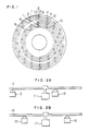
- Fig. 1 shows the concept of recording state on the optical information recording disk according to the first embodiment of this invention
- Figs. 2A and 2B the states of access to information tracks according to the first embodiment of the invention.
- indicated by 1 is an optical guide groove for the outermost track 0 sector 0 on the recording surface of the optical information recording disk.
- 2 is an address information recording section in the form of small pits for the outermost track 0 sector 0, and it has a record of address information including track information and information such as an error check code for the address information, all recorded at manufacturing of the master disk for the optical information recording disk.
- Indicated by 3, 4, 5, 6 and 7 are address information recording sections for track 0 sector 1, track 0 sector 17, track 1 sector 0, track 2 sector 0, and track 2 sector 15, respectively.
- Indicated by 8, 9, 10, 11, 12 and 13 are address information recording sections for the innermost track 0 sector 18, track 0 sector 19, track 0 sector 29, track 1 sector 18, track 2 sector 16, and track 2 sector 29, respectively.
- Figs. 2A and 2B indicated by 14 is the optical information recording disk, 15 and 16 are optical heads, and 17 is a disk spindle motor.
- the optical recording disk of this embodiment has its number of sectors per track increasing by two at each shift of two track positions from inner toward outer tracks. This is the MCAV system and even increasing the number of divisions along the way from inner to outer tracks, if the length of division exceeds a certain length which is set for the innermost track, the number of divisions is increased so that the recording line density is virtually kept constant.
- Each track on the optical recording disk is split into two parts, and it means for the split semicircular tracks that the number of sectors increases by one as the track position shift from inner toward outer tracks.
- tracks given the same number exist in the inner and outer portions.
- Recording video data for a piece or one scene of digital picture occupies all of 30 sectors on track 0, 1.e., from track 0 sector 0 (indicated by 1) following the outer peripheral address recording section 2 up to track 0 sector 17 following the address information recording section 4, and from track 0 sector 18 following the inner address information recording section 8 up to track 0 sector 29 following the address information recording section 10. Similarly, recording the same image information on track 1 will occupy the entirety of track 1. Accordingly, any track has a total of 30 sectors in the inner and outer portions. In this way, from the state of access to the outermost track in the outer portion and innermost track in the inner portion shown in Fig. 2A, the image data is recorded up to respective intermediate tracks shown in Fig. 2B.
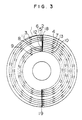
- Fig. 3 shows the concept of recording state on the optical information recording disk according to the second embodiment of this invention.
- indicated by 1 is an optical guide groove for the outermost track 0 sector 0 on the recording surface of the optical recording disk.
- Indicated by 2, 3, 4, 5, 6 and 7 are address information recording sections for the outermost track 0 sector 0, track 0 sector 1, track 0 sector 17, track 1 sector 0, track 2 sector 0, and track 2 sector 15, respectively.
- Indicated by 8, 9, 10, 11, 12 and 13 are address information recording sections for the innermost track 0 sector 18, track 0 sector 19, track 0 sector 29, track 1 sector 18, track 2 sector 16, and track 2 sector 29, respectively.
- the above arrangement is basically identical to that of Fig. 1.
- Indicated by 18 and 19 are address information recording sections in which are recorded track numbers, numbers 0 and 1 for the following two semicircular information recording sections on each track and synchronizing marks recorded in PE modulation of constant recording density per angle, different from the modulation method for the above-mentioned two address information recording sections.
- the optical information recording disk of this embodiment has its number of sections per track increasing by two in each shift of two tracks from inner to outer tracks.
- This is the MCAV system, having the same track arrangement as Fig. 1.
- Each track on the recording disk surface is split into two parts, and the split semicircular tracks are arranged following the address information recording sections 18 and 19.
- This means for half tracks that the number of sectors increases by one at each shift of track position from inner to outer tracks, and correspondence can be made between half tracks starting at the outer position of outer portion and half tracks starting at the inner position of inner portion as the number of tracks increases.
- This correspondent arrangement for each track is basically the same as the embodiment of Fig. 1.
- An agreeable scheme of fast access on the optical information recording disk is to know the address information of the target track and access to the track while controlling by counting the number of tracks to pass thereacross.
- the clock used to read the address information varies depending on the track position, and therefore it is difficult to read the address information during the access.
- recording address information at invariable positions and in CAV system facilitates the reading of track address, resulting in a faster access capability.
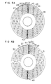
- Figs. 4A and 4B show the concept of recording state of the optical information recording disk according to the third embodiment of this invention
- Figs. 5A and 5B are diagrams showing the track access states according to this embodiment.
- indicated by 20 is an optical guide groove for the outermost track 0 sector 0 on side 1 of the double-sided optical information recording disk.
- Indicated by 21 is an address information recording section in the form of small pits for the outermost track 0 sector 0, and it has a record of address information including track information and information such as an error check code for the address information, all recorded at manufacturing of the master disk for the optical information recording disk.
- Indicated by 22, 23, 24, 25 and 26 are address information recording sections for the outermost track 0 sector 1, track 0 sector 17, track 1 sector 0, track 2 sector 0, and track 2 sector 15, respectively.
- Indicated by 27 and 28 are address information recording sections for the innermost track 9 sector 0, and track 9 sector 9, respectively.
- 29 is an optical guide groove for the innermost track 0 sector 18 on side 2 of the double-sided optical disk.
- 30 is an address information recording section for the innermost track 0 sector 18 which was recorded at manufacturing of the master disk, as for side 1.
- Indicated by 31, 32, 33, 34 and 35 are address information recording sections for track 0 sector 19, track 0 sector 27, track 1 sector 18, track 2 sector 16, and track 2 sector 27, respectively.
- FIGS. 5A and 5B Indicated by 36 and 37 are address information recording sections for the outermost track 9 sector 10 and track 9 sector 27, respectively.
- FIGs. 5A and 5B indicated by 38 is the optical information recording disk, 39 and 40 are optical heads, and 41 is a disk spindle motor.
- the optical recording disk of this embodiment has its number of sectors per track increasing by two at each shift of two track positions from inner toward outer tracks. This is the MCAV system, and even in increasing the number of divisions along the way from inner to outer tracks if the length of division exceeds a certain length which is set for the innermost track, the number of divisions is increased so that the line recording density is virtually kept constant.
- Each track on side 1 and side 2 of the optical information recording disk is split into two parts, and it means for the split semicircular tracks that the number of sectors increases by one as the track position shift from inner toward outer tracks.
- tracks given the same number exist on both the side 1 and side 2.
- Recording video data for a piece of digital picture occupies all of 28 sectors on track 0, i.e., from track 0 sector 0 (indicated by 20) following the address recording section 21 up to track 0 sector 17 following the address information recording section 23, and from track 0 sector 18 following the address information recording section 30 on side 2 up to track 0 sector 27 following the address information recording section 32.
- recording the same image information on track 1 will occupy the entirety of track 1. Accordingly, any track has a total of 28 sectors on side 1 and side 2. In this way, image data is recorded from the state of access to track 0 on side 1 shown in Fig. 5A up to the state of access to track 9 shown in Fig. 5B.
- Figs. 6A and 6B show the concept of recording state on the optical recording disk according to the fourth embodiment of this invention.
- indicated by 20 is an optical guide groove for the outermost track 0 sector 0 on side 1 of the double-sided optical disk.
- Indicated by 21, 22, 23, 24, 25 and 26 are address information recording sections for the outermost track 0 sector 0, track 0 sector 1, track 0 sector 17, track 1 sector 0, track 2 sector 0, and track 2 sector 15, respectively.
- Indicated by 27 and 28 are address information recording sections for the innermost track 9 sector 0, and track 9 sector 9, respectively.
- the arrangement is basically identical to that of Fig. 4.
- Indicated by 42 and 43 are address information recording sections in which are recorded track numbers, numbers 0 and 1 for the following two semicircular information recording sections on each track and synchronizing marks recorded in PE modulation of constant recording density per angle, different from the modulation method for the above-mentioned address information recording sections 21.
- 29 is an optical guide groove for the innermost track 0 sector 18 on side 2 of the double-sided optical disk.
- 30, 31, 32, 33, 34 and 35 are address information recording sections for the outermost track 0 sector 18, track 0 sector 19, track 0 sector 27, track 1 sector 18, track 2 sector 17, and track 2 sector 27, respectively.
- Indicated by 36 and 37 are address information recording sections for the outermost track 9 sector 10, and track 9 sector 27, respectively.
- Indicated by 44 and 45 are address information recording sections in which are recorded track numbers, numbers 0 and 1 for the following two semicircular information recording sections on each track and synchronizing marks recorded in PE modulation of constant recording density per angle, different from the modulation method for the above-mentioned address information recording sections 30.
- the optical recording disk of this embodiment has its number of sectors per track increasing by two at each shift of two tracks from inner toward outer tracks.
- This is the MCAV system, having the same track arrangement as Fig. 4.
- Each track on side 1 and side 2 of disk is split into two parts, and the split semi-circular tracks are arranged following the address information recording sections 42, 43, 44 and 45.
- This means for half tracks that the number of sectors increases by one at each shift of position from inner toward outer tracks, and a correspondence can be made between half tracks starting at the outer peripheral position of side 1 and half tracks starting at the inner peripheral position of side 2 as the number of tracks increases.
- This correspondent arrangement for each track is basically the same as the third embodiment.
- An agreeable scheme of fast access on the optical information recording disk is to know the address information of the target track and access to the track while controlling by counting the number of tracks to pass thereacross.
- the clock used to read the address information varies depending on the track position, and therefore it is difficult to read the address information during the access.
- recording of address information at invariable positions and yet according to CAV system facilitates the reading of track address, resulting in a faster access capability.
- Each semicircular track on side 1 and side 2 has a total of 28 sectors, and this is substantially equal to the transfer rate at an intermediate track position on the optical information recording medium. It enables faster data transfer as compared with the CAV system, and is suitable for recording and reproducing digital video pictures.
- Fig. 7 is a block diagram of the optical information recording apparatus which is the fifth embodiment of this invention. Shown in Fig. 7 by 38 is a double-sided optical information recording disk, 39 and 40 are optical heads, 41 is a disk spindle motor, 46 and 47 are binary threshold circuits, 48 and 49 are optical head drive control circuits, 50 and 51 are address information detecting circuits, 52 and 53 are PLL circuits, 54 and 55 are error correcting circuits, 56 and 57 are buffer memories, 58 and 59 are laser drive circuits, 60 is a control microcomputer, and 61 is a distributing-merging circuit.
- Figs. 5A and 5B are diagrams showing the scene of track access according to the fifth embodiment of this invention. In the figure, indicated by 39 and 40 are optical heads, and 41 is a disk spindle motor.
- the optical recording disk of this embodiment has its number of sectors per track increasing by one at each shift of one track position from inner toward outer tracks.
- This is the MCAV system, having a constant recording density per sector by increasing the sector length along the way from inner toward outer tracks, and if the length of divided sectors exceeds a certain length determined for the innermost track despite an increased number of divisions at the circumference, the number of divisions is further increased so that the line recording density of each sector is substantially constant. It is assumed that such a recording surface exists on both of side 1 and side 2 of the optical information recording disk, and the innermost and outermost portions include 10 sectors and 18 sectors, respectively.
- the control microcomputer 60 operates on the optical head drive circuits 48 and 49 to have a seek operation for the optical heads 39 and 40 so that the address information read out by the binary threshold circuits 46 and 47 and address information detecting circuits 50 and 51 becomes equal to the specific address.
- binary information sent from the host computer by way of the distributing-merging circuit 61 is distributed to the buffer memories 56 and 57 in quantities proportional to the numbers of sectors on the respective tracks, and, after being appended with error correcting codes by the error correcting circuits 54 and 55, the information is recorded on the optical information recording disk 38 by the laser drivers 58 and 59.
- the control computer 60 sets up in advance the synthesized oscillators within the PLL circuits 52 and 53 so that they oscillate comparing source oscillation frequencies corresponding to the target track addresses, and reads out the recorded information which has been quantized in binary by the binary threshold circuits 46 and 47 using the source oscillation frequencies and the reproduction clock produced by the PLL circuits, and, after the correcting process by the error correcting circuits 54 and 55, sends the information to the buffer memories 56 and 57.
- the data from the buffer memories are merged by the distributing-merging circuit 61, and sent to the host computer.
- the data transfer rate from the host computer at recording and to the host computer at reproduction is equivalently 28 sectors per disk revolution. Shown in Figs. 5A and 5B are head positions after the optical heads 39 and 40 had started access to respective sectors (Fig. 5A), and when the heads have completed recording of a total of 10 pieces of image data on the entire surfaces of the optical recording disk (Fig. 5B).
- Fig. 8 shows in block diagram the optical information recording disk apparatus according to the sixth embodiment of this invention.
- 38 is an optical information recording disk
- 39 and 40 are optical heads
- 41 is a disk spindle motor
- 46 and 47 are binary threshold circuits
- 48 and 49 are optical head drive control circuits
- 50 and 51 are address information detecting circuits
- 52 and 53 are PLL circuits
- 54 and 55 are error correcting circuits
- 56 and 57 are buffer memories
- 58 and 59 are laser drive circuits
- 60 is a microcomputer
- 61 is distributing-merging (combining) circuit.
- Indicated by 62 and 63 are input signal switching circuits
- 64 and 65 are output signal switching circuits.
- Indicated by 38 is an optical guide groove for the outermost track 0 sector 0 on side 1 of the double-sided optical information recording disk.
- the optical information recording disk of this embodiment has its number of sectors per track increasing by one at each shift of one track along the way from inner toward outer tracks. It is assumed that image data for a piece of digital picture has a capacity equivalently equal to 28 sectors. In recording the data on the optical information recording disk, it is further assumed that data recording has started on the innermost track of side 1 and the outermost track of side 2 of the optical recording disk, while storing data for the innermost 10 sectors and outermost 18 sectors in the buffer memories 56 and 57, in a period of time when the optical recording disk 38 turns one revolution.
- Image data of equally equivalent to 28 sectors are written in the buffer memories 56 and 57 in a proportion of quantities of 17 sectors and 11 sectors, respectively, and during the next one revolution of the optical recording disk, data is recorded on the track next to the outermost track and in the sector next to the innermost track, after the output switch circuits 64 and 65 have been reversed. Similarly, the input switch circuits 62 and 63 are also reversed in every second revolution at reproduction. Consequently, the quantity of data entered to the buffer memory circuits 56 and 57 does not exceed the data capacity equivalent to the maximum 28 sectors. Data control is relatively simple.
- the first, third and fifth embodiments have been described on assumption that the total number of tracks is eight or ten, the track pitch is usually around 1.6 ⁇ m and there are almost 1000 tracks having a same number of divisions, and an optical information recording disk has a total number of tracks of the order of ten thousands on one side.
- the first information recording sections are provided at every 360 degrees, the number of divisions of track can be increased by one track increment along the way from inner toward outer tracks.
- the address information recording sections are recorded as small pits, it is of course possible to record these sections in any method which allows optical read out. Instead of arranging the address information sections 14 and 15, or 42, 43, 44 and 45, each sector address information may be omitted.
- Double tracks may be formed so that fast recording and reproduction are possible by dual-beam recording, or two pairs of optical heads may be provided to accomplish the same effectiveness.
- the rotation of the optical information recording disk may be synchronized with the vertical sync signal of the analog image data for the recording and reproduction of video images.
- tracks in the inner and outer portions of an optical information recording disk are combined so that the circumferential sum is constant, or circumferential sum of tracks on both sides of a double-sided optical recording disk is constant, thereby making constant the sum of corresponding sectors on both sides which is set in the MCAV system.
- Information in batch of certain quantity is recorded on logical tracks, for example, whereby the mass storage capability of the MCAV system and easy information control quality based on track or sector of the CAV system can be realized at the same time.
- the fast access performance of the CAV system and fast continuous data transfer at a low disk speed can be realized.
Landscapes
- Physics & Mathematics (AREA)
- Optics & Photonics (AREA)
- Engineering & Computer Science (AREA)
- Signal Processing (AREA)
- Optical Recording Or Reproduction (AREA)
- Signal Processing For Digital Recording And Reproducing (AREA)
Claims (5)
- Optische Informationsaufzeichnungsplatte mit in einem konstanten Winkelabstand auf spiraligen Spuren vorgesehenen ersten Informationsaufzeichnungsabschnitten, die getrennt, in gleicher Anzahl, in einem inneren Umfangsbereich und einem äußeren Umfangsbereich auf einer Seite einer Platte (14) vorgesehen sind; unterteilten Informationsabschnitten, die durch Teilen eines Teils oder aller ersten Informationsaufzeichnungsabschnitte vorgesehen sind, wobei die unterteilten Informationsabschnitte jeweils eine Länge länger als eine vorgegebene Länge haben und eine in Abhängigkeit vom Radius der Spur bestimmte maximal zulässige Anzahl von Unterteilungen pro erstem Informationsaufzeichnungsabschnitt haben; und Adreßinformationsabschnitten (2-13) auf den spiraligen Spuren zum Identifizieren des Ortes, wo eine Information aufgezeichnet ist, wobei Information auf die spiraligen Spuren in dem inneren Bereich ausgehend von den inneren zu den äußeren Spuren aufgezeichnet wird, Information auf den spiraligen Spuren in dem äußeren Bereich mit einer von der der Spuren im inneren Bereich verschiedenen Spiralrichtung ausgehend von den äußeren zu den inneren Spuren aufgezeichnet wird, eine Informationsserie derart unterteilt aufgezeichnet wird, daß die ersten Informationsaufzeichnungsabschnitte auf einer bestimmten Spur in dem inneren Bereich mit den ersten Informationsaufzeichnungsabschnitten auf einer bestimmten Spur in dem äußeren Bereich korrespondieren, und die bestimmten Spuren auf eine derartige Beziehung beschränkt sind, daß die Summe der Anzahlen von Unterteilungen pro erstem Informationsaufzeichnungsabschnitt in dem inneren Bereich und dem äußeren Bereich gleich ist zur Summe einer Anzahl von Unterteilungen des ersten Informationsaufzeichnungsabschnittes im innersten Umfang und einer Anzahl von Unterteilungen des äußersten Umfangs.
- Optische Informationsaufzeichnungsplatte mit in einem gleichbleibenden Winkelabstand auf spiraligen Spuren vorgesehenen ersten Informationsaufzeichnungsabschnitten, die in gleicher Anzahl auf beiden Seiten einer Platte (38) vorgesehen sind; unterteilten Informationsabschnitten, die durch Teilen eines Teils oder aller der ersten Informationsaufzeichnungsabschnitte vorgesehen sind, wobei die unterteilten Informationsabschnitte jeweils eine Länge, die länger ist als eine vorgegebene Länge, haben und eine in Abhängigkeit vom Radius der Spur bestimmte maximal zulässige Anzahl von Unterteilungen pro erstem Informationsaufzeichnungsabschnitt haben; und Adreßinformationsabschnitten auf den spiraligen Spuren zum Identifizieren des Ortes, wo eine Information aufgezeichnet ist, wobei Information auf den spiraligen Spuren auf einer ersten Fläche der Platte ausgehend von den inneren zu den äußeren Spuren aufgezeichnet wird, Information auf den spiraligen Spuren auf einer zweiten Fläche der Platte mit gleicher Spiralrichtung wie die Spuren auf der ersten Fläche der Platte ausgehend von den äußeren zu den inneren Spuren aufgezeichnet wird, eine Informationsserie derart unterteilt aufgezeichnet wird, daß die ersten Informationsaufzeichnungs-abschnitte auf einer bestimmten Spur auf der ersten Fläche mit den ersten Informationsaufzeichnungsabschnitten auf einer bestimmten Spur auf der zweiten Fläche korrespondieren, und die bestimmten Spuren auf eine solche Beziehung beschränkt sind, daß die Summe der Anzahlen von Unterteilungen pro erstem Informationsaufzeichnungsabschnitt auf der ersten Fläche und der zweiten Fläche gleich ist zu der Summe einer Anzahl von Unterteilungen des ersten Informationsaufzeichnungsab-schnitts in dem innersten Umfang und einer Anzahl von Unterteilungen des äußersten Umfangs.
- Optische Informationsaufzeichnungsplatte nach Anspruch 1 oder 2, weiter mit zweiten Informationsaufzeichnungsabschnitten (18,19;42-45), die eine mit einer gleichbleibenden Aufzeichnungsdichte pro Winkel in Form kleiner Vertiefungen oder Vorsprünge auf den spiraligen Spuren aufgezeichnete Adreßinformation enthalten, wobei die zweiten Informationsaufzeichnungsabschnitte den ersten Informationsaufzeichnungsabschnitten vorangehen.
- Optisches Informationsaufzeichnungsplattengerät enthaltend: eine optische Informationsaufzeichnungsplatte (14, 38) mit Adreßinformationsabschnitten auf Spuren zum Identifizieren des Ortes, wo eine Information aufgezeichnet ist, in einem gleichbleibenden Winkelabstand auf den Spuren vorgesehenen ersten Informationsaufzeichnungsabschnitten, und unterteilten Informationsabschnitten, die durch Teilen eines Teils oder aller ersten Informationsaufzeichnungsabschnitte vorgesehen sind, wobei die unterteilten Informationsabschnitte jeweils eine Länge, die länger ist als eine vorgegebene Länge, haben und eine in Abhängigkeit vom Radius der Spur bestimmte maximal zulässige Anzahl von Unterteilungen pro erstem Informationsaufzeichnungsabschnitt haben; mindestens ein Paar von Köpfen (39,40) zum Schreiben oder Lesen von Information auf der optischen Informationsaufzeichnungsplat-te; eine Einrichtung (46) zum Umsetzen von von der optischen Informationsaufzeichnungsplatte ausgelesener InformatIon in binäre Information; einen Pufferspeicher (56,57) zum Speichern von von den Köpfen geschriebener oder gelesener binärer Information; eine Einrichtung zum Drehen der optischen Informationsaufzeichnungsplatte mit einer gleichbleibenden Winkelgeschwindigkeit; eine Einrichtung (150) zum Identifizieren der Adreßinformation; eine Einrichtung zum Aufzeichnen einer gleichbleibenden Menge von Information pro unterteiltem Informationsabschnitt, wobei das Paar von Köpfen auf verschiedene Spuren zugreift, die zu verschiedenen Gruppen gehören; und eine Einrichtung (46,47,50,51,60) zum Steuern des Spurführungsortes jedes der Köpfe, so daß sie sich in entgegengesetzten radialen Richtungen bewegen, wobei deren Orte derart in Beziehung stehen, daß die Summe der Anzahlen von Unterteilungen der ersten Informationsaufzeichnungsabschnitte, auf die während jeder Umdrehung der Platte von beiden Köpfen zugegriffen wird, ein konstanter Wert ist, und daß beim Aufzeichnen eine in der Menge der Summe von Unterteilungen entsprechende Menge aufzuzeichnender binärer Information während jeder bestimmten Winkeldrehung der Platte in den Pufferspeicher geschrieben wird, und danach die binäre Information aus dem Pufferspeicher ausgelesen und in Abhängigkeit von der Unterteilungsanzahl auf das Paar von Köpfen verteilt den unterteilten Informationsabschnitten zugeführt wird, und bei der Wiedergabe von dem Paar von Köpfen aufgenommene Information in binäre umgesetzt und in den Pufferspeicher geschrieben wird und während der Winkeldrehung der optischen Informationsaufzeichnungsplatte binäre Information in einer der Summe von Unterteilungsanzahlen entsprechenden Menge aus dem Pufferspeicher ausgelesen wird.
- Optisches Informationsaufzeichnungsplattengerät nach Anspruch 4, bei dem für die Aufzeichnung mindestens ein Paar von Schalteranordnungen (64,65) vorgesehen sind, die für die Ausgabe binärer Information aus dem Paar von Pufferspeichern einen aus dem Paar von Köpfen auswählen, wobei die Schalteranordnungen während jeder Winkelumdrehung der optischen Informationsaufzeichnungsplatte umgeschaltet werden, um dadurch einen anderen Kopf auszuwählen, durch den binäre Information auf die optische Informationsaufzeichnungsplatte geschrieben wird, und bei dem zur Wiedergabe Schaltanordnungen (62,63) vorgesehen sind, die einen aus dem Paar von Köpfen für die Eingabe binärer Information aus dem Paar von Pufferspeichern auswählen, wobei die Schalteranordnungen während jeder Winkelumdrehung der optischen Informationsaufzeichnungsplatte umgeschaltet werden, um dadurch einen anderen Kopf auszuwählen, durch den ausgelesene binäre Information in die Pufferspeicher eingeschrieben wird.
Applications Claiming Priority (6)
| Application Number | Priority Date | Filing Date | Title |
|---|---|---|---|
| JP311359/86 | 1986-12-25 | ||
| JP311358/86 | 1986-12-25 | ||
| JP61311360A JPH07122962B2 (ja) | 1986-12-25 | 1986-12-25 | 情報記録円盤装置 |
| JP311360/86 | 1986-12-25 | ||
| JP61311358A JP2583867B2 (ja) | 1986-12-25 | 1986-12-25 | 光学式情報記録円盤 |
| JP61311359A JP2583868B2 (ja) | 1986-12-25 | 1986-12-25 | 光学式情報記録円盤 |
Publications (2)
| Publication Number | Publication Date |
|---|---|
| EP0273384A1 EP0273384A1 (de) | 1988-07-06 |
| EP0273384B1 true EP0273384B1 (de) | 1991-03-20 |
Family
ID=27339167
Family Applications (1)
| Application Number | Title | Priority Date | Filing Date |
|---|---|---|---|
| EP87119118A Expired EP0273384B1 (de) | 1986-12-25 | 1987-12-23 | Optische Informationsaufzeichnungsplatte und Gerät dafür |
Country Status (4)
| Country | Link |
|---|---|
| US (1) | US4873679A (de) |
| EP (1) | EP0273384B1 (de) |
| CA (1) | CA1300261C (de) |
| DE (1) | DE3768795D1 (de) |
Families Citing this family (74)
| Publication number | Priority date | Publication date | Assignee | Title |
|---|---|---|---|---|
| US5343453A (en) * | 1988-12-01 | 1994-08-30 | Canon Kabushiki Kaisha | Method for accessing desired track on disk with plurality of recording zones with head, and apparatus therefore |
| US5239533A (en) * | 1989-01-06 | 1993-08-24 | Kabushiki Kaisha Toshiba | Information recording medium |
| US5568454A (en) * | 1989-03-09 | 1996-10-22 | Tosoh Corporation | Apparatus and method for detecting a defect on a magneto-optical disk |
| JP2796829B2 (ja) * | 1989-03-28 | 1998-09-10 | キヤノン株式会社 | 情報記録装置 |
| JPH0646487B2 (ja) * | 1989-03-31 | 1994-06-15 | キヤノン株式会社 | 情報記録再生方法、情報記録再生装置及び情報記録担体 |
| JP2589370B2 (ja) * | 1989-04-13 | 1997-03-12 | シャープ株式会社 | 光ディスク装置 |
| US5276669A (en) * | 1989-04-21 | 1994-01-04 | The Tokyo Electric Power Co., Inc. | Synchronous recording and playback of left and right stereo channels on separate digital discs |
| US5245594A (en) * | 1989-05-17 | 1993-09-14 | Fuji Electric Co., Ltd. | Data read/write system for a disc storage unit |
| US5111345A (en) * | 1989-05-26 | 1992-05-05 | The United States Of America As Represented By The Administrator, National Aeronautics & Space Administration | Disk memory device |
| JPH0363966A (ja) * | 1989-08-01 | 1991-03-19 | Pioneer Electron Corp | ディスク演奏装置 |
| US5197049A (en) * | 1989-08-11 | 1993-03-23 | Apple Computer, Inc. | Head and media for optical data storage |
| US5182741A (en) * | 1989-08-25 | 1993-01-26 | Sharp Kabushiki Kaisha | Optical disk recording/reproducing device utilizing a constant angular velocity method with a constant linear velocity formatted optical disk |
| JPH0766547B2 (ja) * | 1989-08-31 | 1995-07-19 | 富士通株式会社 | 光デイスク装置 |
| JP2797579B2 (ja) * | 1989-12-28 | 1998-09-17 | ソニー株式会社 | 目標トラック位置検索装置 |
| US5210660A (en) * | 1990-01-17 | 1993-05-11 | International Business Machines Corporation | Sectored servo independent of data architecture |
| US5235591A (en) * | 1990-01-19 | 1993-08-10 | Hitachi, Ltd. | Stack type optical disc apparatus, sealed and separate type optical head therefor and optical disc medium |
| EP0440224B1 (de) * | 1990-02-01 | 1996-04-03 | Matsushita Electric Industrial Co., Ltd. | Gerät zur Wiedergabe von Daten, um eine hohe Übertragungsgeschwindigkeit zu realisieren |
| JP2536947B2 (ja) * | 1990-02-23 | 1996-09-25 | パイオニア株式会社 | ディスクの記録及び読取方法 |
| US5418774A (en) * | 1990-03-23 | 1995-05-23 | Matsushita Electric Industrial Co., Ltd. | Optical head system and its optical disc |
| JPH04184782A (ja) * | 1990-11-20 | 1992-07-01 | Matsushita Electric Ind Co Ltd | 光ディスク装置 |
| JPH04301222A (ja) * | 1991-03-28 | 1992-10-23 | Toshiba Corp | ディスク再生装置 |
| US5202799A (en) * | 1991-06-24 | 1993-04-13 | Ibm Corporation | Logical data tracks extending among a plurality of zones of physical tracks of one or more disk devices |
| JPH056575A (ja) * | 1991-06-28 | 1993-01-14 | Toshiba Corp | 情報記憶媒体 |
| EP0532998A1 (de) * | 1991-09-16 | 1993-03-24 | Eastman Kodak Company | Bildstellung angebende Photo-CD sowie Verfahren und Vorrichtung zu deren Verwendung |
| JP3199799B2 (ja) * | 1991-12-17 | 2001-08-20 | パイオニア株式会社 | 情報記録装置 |
| JP3311770B2 (ja) * | 1992-02-03 | 2002-08-05 | ローム株式会社 | ハードディスクドライブ装置 |
| US5293565A (en) * | 1992-02-04 | 1994-03-08 | International Business Machines Corporation | Fortmat for data-storing disk media wherein addressable track angular length is independent of disk revolutions |
| US5528574A (en) * | 1992-03-09 | 1996-06-18 | Hitachi, Ltd. | Disk reproducing apparatus capable of increasing speed of access to disks recorded at constant linear velocity |
| JPH0636473A (ja) * | 1992-07-16 | 1994-02-10 | Matsushita Electric Ind Co Ltd | 光情報記録装置及びその方法 |
| JP3225611B2 (ja) * | 1992-07-27 | 2001-11-05 | 松下電器産業株式会社 | ディスク再生装置 |
| US6529451B2 (en) * | 1992-10-05 | 2003-03-04 | Mitsubishi Denki Kabushiki Kaisha | Optical disk and optical disk drive device |
| US7548497B2 (en) * | 1992-10-05 | 2009-06-16 | Mitsubishi Denki Kabushiki Kaisha | Optical disk and optical disk drive device |
| JP3078686B2 (ja) * | 1992-10-05 | 2000-08-21 | 三菱電機株式会社 | 光ディスク、光ディスク駆動装置および光ディスクの書き込み読み出し方法 |
| KR100230892B1 (ko) * | 1992-10-20 | 1999-11-15 | 모리시타 요이찌 | 디스크장치 |
| US5315568A (en) * | 1992-11-12 | 1994-05-24 | International Business Machines Corporation | Apparatus and method for accessing sectors of a rotating disk |
| JPH06162557A (ja) * | 1992-11-18 | 1994-06-10 | Matsushita Electric Ind Co Ltd | 光学的記録再生装置 |
| JP3106750B2 (ja) * | 1992-12-11 | 2000-11-06 | 松下電器産業株式会社 | ディスク再生装置 |
| US5563859A (en) * | 1993-04-07 | 1996-10-08 | Matsushita Electric Industrial Co., Ltd. | Method for simultaneous recording and playback from both sides of a recording medium |
| JPH076492A (ja) * | 1993-06-15 | 1995-01-10 | Toshiba Corp | データ記録再生装置 |
| US5583712A (en) * | 1993-06-24 | 1996-12-10 | Maxtor Corporation | Magnetic recording system having spiral tracks |
| JP2601144B2 (ja) * | 1993-07-19 | 1997-04-16 | 日本電気株式会社 | Cwl−cav方式の光ディスク装置 |
| JPH0778418A (ja) * | 1993-09-10 | 1995-03-20 | Matsushita Electric Ind Co Ltd | 光ディスク及び光学的記録再生装置 |
| US5510905A (en) * | 1993-09-28 | 1996-04-23 | Birk; Yitzhak | Video storage server using track-pairing |
| US5535182A (en) * | 1993-11-04 | 1996-07-09 | Nec Corporation | Optical disk apparatus and recording/reproduction method therefor |
| JP3017382B2 (ja) * | 1993-11-11 | 2000-03-06 | 富士通株式会社 | 光ディスク装置 |
| US5590101A (en) * | 1994-05-31 | 1996-12-31 | Nec Corporation | Track jump controller for optical disk recording |
| NL1001647C2 (nl) * | 1994-11-16 | 1997-10-21 | Nec Corp | Herschrijfbare optische-schijfinrichting. |
| US5596458A (en) * | 1994-12-19 | 1997-01-21 | Integral Peripherals, Inc. | Variable zone layout for information storage disk drive |
| US6091559A (en) * | 1994-12-19 | 2000-07-18 | Mobile Storage Technology Inc. | Variable zone layout and track pitch parameter considerations for information storage disk drive |
| US5630760A (en) * | 1995-02-07 | 1997-05-20 | The Little Tikes Company | Convertible game table |
| USD368281S (en) | 1995-02-07 | 1996-03-26 | The Little Tikes Company | Activity table |
| JPH08249824A (ja) * | 1995-03-15 | 1996-09-27 | Nikon Corp | 光ディスク再生装置及び光ディスク記録装置 |
| US5721878A (en) * | 1995-06-07 | 1998-02-24 | International Business Machines Corporation | Multimedia control system and method for controlling multimedia program presentation |
| JPH0917119A (ja) * | 1995-06-30 | 1997-01-17 | Sony Corp | データ記録媒体、データ記録方法及びデータ再生方法 |
| JP3019142B2 (ja) * | 1995-08-31 | 2000-03-13 | 日本ビクター株式会社 | 書換型光ディスクの記録方法 |
| US5793549A (en) * | 1995-11-15 | 1998-08-11 | Zen Research N.V. | Methods and apparatus for synchronizing read out of data from multiple tracks of an optical storage device |
| US6381210B1 (en) | 1995-11-15 | 2002-04-30 | Zen Research (Ireland) Ltd. | Methods and apparatus for concurrently processing data from multiple tracks of an optical storage medium |
| US5907526A (en) * | 1995-11-15 | 1999-05-25 | Zen Research N.V. | Methods and apparatus for simultaneously reading multiple tracks of an optical storage medium |
| WO1999018570A1 (en) * | 1997-10-03 | 1999-04-15 | Koninklijke Philips Electronics N.V. | A method and apparatus for providing enhanced transfer rate for a constant angular velocity storage disc |
| US20030027173A1 (en) * | 1998-01-16 | 2003-02-06 | Della-Cioppa Guy | Method of determining the function of nucleotide sequences and the proteins they encode by transfecting the same into a host |
| SG93198A1 (en) | 1998-04-20 | 2002-12-17 | Samsung Electronics Co Ltd | Recording medium for storing defect management information for recording real time data, defect managing method therefor, and real time data recording method |
| US6137763A (en) * | 1998-09-24 | 2000-10-24 | Zen Research N.V. | Method and apparatus for buffering data in a multi-beam optical disk reader |
| DE19859069A1 (de) * | 1998-12-22 | 2000-07-06 | Thomson Brandt Gmbh | Wiedergabegerät für doppelseitige Aufzeichnungsträger |
| JP4118475B2 (ja) | 1999-09-21 | 2008-07-16 | 株式会社日立国際電気 | 映像記録再生方法および装置 |
| US7342741B1 (en) | 2000-02-10 | 2008-03-11 | Esgw Holdings Limited | Disk drive with variable track density |
| GB0031439D0 (en) | 2000-12-22 | 2001-02-07 | Koninkl Philips Electronics Nv | Method and apparatus for data reproduction |
| US7514037B2 (en) * | 2002-08-08 | 2009-04-07 | Kobe Steel, Ltd. | AG base alloy thin film and sputtering target for forming AG base alloy thin film |
| JP3823939B2 (ja) * | 2003-04-23 | 2006-09-20 | ソニー株式会社 | 再生装置および方法 |
| KR20040099529A (ko) * | 2003-05-19 | 2004-12-02 | 삼성전자주식회사 | 소형 광 디스크, 소형 광 디스크에 데이터를 기록하는데이터 기록 장치 및 그 방법 |
| US7561359B1 (en) * | 2003-06-02 | 2009-07-14 | Maxtor Corporation | Spiral servo patterns with absolute reference point |
| US20050105456A1 (en) * | 2003-11-18 | 2005-05-19 | Cookson Christopher J. | Double-sided optical disc |
| CN1882995A (zh) * | 2003-11-18 | 2006-12-20 | 皇家飞利浦电子股份有限公司 | 用于记录介质的复制保护系统 |
| US7327648B2 (en) * | 2003-11-19 | 2008-02-05 | Warner Bros. Home Entertainment Inc. | Player with rotational control for double-sided optical discs |
| US20050105457A1 (en) * | 2003-11-19 | 2005-05-19 | Cookson Christopher J. | Double-sided optical disc with means for indicating its proper direction of rotation |
Family Cites Families (10)
| Publication number | Priority date | Publication date | Assignee | Title |
|---|---|---|---|---|
| US4357635A (en) * | 1979-03-20 | 1982-11-02 | Ricoh Company, Ltd. | Disc memory apparatus |
| JPS57111811A (en) * | 1980-12-29 | 1982-07-12 | Fujitsu Ltd | Magnetic disk device |
| JPS58175142A (ja) * | 1983-03-14 | 1983-10-14 | Hitachi Ltd | 情報記録方式 |
| JPH0812743B2 (ja) * | 1983-06-30 | 1996-02-07 | 株式会社東芝 | ディスク装置 |
| EP0164061B1 (de) * | 1984-06-01 | 1989-05-17 | Matsushita Electric Industrial Co., Ltd. | Optische Platte ausschliesslich zur Wiedergabe |
| US4884259A (en) * | 1984-08-28 | 1989-11-28 | Fuji Photo Film Co., Ltd. | Optical memory disk and track access therefor |
| US4712204A (en) * | 1984-08-31 | 1987-12-08 | Matsushita Electric Industrial Co., Ltd. | Optical disk and method for reproducing reference signal therefrom |
| JPS6196583A (ja) * | 1984-10-17 | 1986-05-15 | Sony Corp | ディスク記録再生装置 |
| NL8501189A (nl) * | 1985-04-25 | 1986-11-17 | Philips Nv | Registratiedrager en inrichting voor het vervaardigen van zo'n registratiedrager. |
| US4799112A (en) * | 1987-02-19 | 1989-01-17 | Magnetic Peripherals Inc. | Method and apparatus for recording data |
-
1987
- 1987-12-21 US US07/135,453 patent/US4873679A/en not_active Expired - Lifetime
- 1987-12-23 DE DE8787119118T patent/DE3768795D1/de not_active Expired - Lifetime
- 1987-12-23 EP EP87119118A patent/EP0273384B1/de not_active Expired
- 1987-12-24 CA CA000555419A patent/CA1300261C/en not_active Expired - Lifetime
Also Published As
| Publication number | Publication date |
|---|---|
| DE3768795D1 (de) | 1991-04-25 |
| EP0273384A1 (de) | 1988-07-06 |
| CA1300261C (en) | 1992-05-05 |
| US4873679A (en) | 1989-10-10 |
Similar Documents
| Publication | Publication Date | Title |
|---|---|---|
| EP0273384B1 (de) | Optische Informationsaufzeichnungsplatte und Gerät dafür | |
| US4984227A (en) | Optical disc device | |
| KR100295215B1 (ko) | 디스크기록재생방식 | |
| US4750059A (en) | Data recording format for an information-bearing disk | |
| US4001883A (en) | High density data storage on magnetic disk | |
| US6151292A (en) | Optical disk having sequentially numbered sectors and logical tracks formed by a series of 2n sectors, and disk drive apparatus for using such an optical disk | |
| US4789979A (en) | Optical disk exclusively used for reproduction wherein guide grooves located between data managing information and data recording regions have no track address sections | |
| EP0833319A2 (de) | Plattenförmiges Aufzeichnungsmedium | |
| US7924693B2 (en) | Optical disk and optical disk drive device | |
| US4780866A (en) | Method and apparatus combining an information-bearing disk and a disk drive mechanism | |
| JPH08249824A (ja) | 光ディスク再生装置及び光ディスク記録装置 | |
| US5808995A (en) | Disk information reading control apparatus having a variable read transfer speed and a disk information reading control method | |
| EP0758124B1 (de) | Informationsaufzeichnungs-/-wiedergabegerät mit veränderlicher Drehzahl und Datentaktfrequenz | |
| EP0437202A1 (de) | Aufzeichnungs-/Wiedergabegerät zur Informationsaufzeichnung und Überprüfung aufgezeichneter Information | |
| JP2583867B2 (ja) | 光学式情報記録円盤 | |
| JPH07122962B2 (ja) | 情報記録円盤装置 | |
| JPH0434764A (ja) | 磁気ディスク | |
| US5850381A (en) | Method of recording information on a disc by recording information at interleaved sectors | |
| JP2583868B2 (ja) | 光学式情報記録円盤 | |
| KR100293561B1 (ko) | 불연속섹터형태의디스크 | |
| JP2001143268A (ja) | 光ディスク媒体およびその記録方法、記録装置 | |
| JPH11213567A (ja) | 光ディスク再生装置及び光ディスク記録装置 | |
| JPH07262692A (ja) | ディスク記録再生方式 | |
| JP2000207813A (ja) | ディスク記録装置、ディスク再生装置、及びディスク状記録媒体 | |
| JP2000215459A (ja) | ディスク状記録媒体 |
Legal Events
| Date | Code | Title | Description |
|---|---|---|---|
| PUAI | Public reference made under article 153(3) epc to a published international application that has entered the european phase |
Free format text: ORIGINAL CODE: 0009012 |
|
| AK | Designated contracting states |
Kind code of ref document: A1 Designated state(s): DE FR GB |
|
| 17P | Request for examination filed |
Effective date: 19880909 |
|
| 17Q | First examination report despatched |
Effective date: 19900504 |
|
| GRAA | (expected) grant |
Free format text: ORIGINAL CODE: 0009210 |
|
| AK | Designated contracting states |
Kind code of ref document: B1 Designated state(s): DE FR GB |
|
| REF | Corresponds to: |
Ref document number: 3768795 Country of ref document: DE Date of ref document: 19910425 |
|
| ET | Fr: translation filed | ||
| PLBE | No opposition filed within time limit |
Free format text: ORIGINAL CODE: 0009261 |
|
| STAA | Information on the status of an ep patent application or granted ep patent |
Free format text: STATUS: NO OPPOSITION FILED WITHIN TIME LIMIT |
|
| 26N | No opposition filed | ||
| REG | Reference to a national code |
Ref country code: GB Ref legal event code: IF02 |
|
| REG | Reference to a national code |
Ref country code: GB Ref legal event code: 746 Effective date: 20031002 |
|
| REG | Reference to a national code |
Ref country code: FR Ref legal event code: D6 |
|
| PGFP | Annual fee paid to national office [announced via postgrant information from national office to epo] |
Ref country code: FR Payment date: 20061208 Year of fee payment: 20 |
|
| PGFP | Annual fee paid to national office [announced via postgrant information from national office to epo] |
Ref country code: GB Payment date: 20061220 Year of fee payment: 20 |
|
| PGFP | Annual fee paid to national office [announced via postgrant information from national office to epo] |
Ref country code: DE Payment date: 20061221 Year of fee payment: 20 |
|
| REG | Reference to a national code |
Ref country code: GB Ref legal event code: PE20 |
|
| PG25 | Lapsed in a contracting state [announced via postgrant information from national office to epo] |
Ref country code: GB Free format text: LAPSE BECAUSE OF EXPIRATION OF PROTECTION Effective date: 20071222 |