EP0257219B1 - Châssis de transport pour plaques de verre - Google Patents
Châssis de transport pour plaques de verre Download PDFInfo
- Publication number
- EP0257219B1 EP0257219B1 EP87108687A EP87108687A EP0257219B1 EP 0257219 B1 EP0257219 B1 EP 0257219B1 EP 87108687 A EP87108687 A EP 87108687A EP 87108687 A EP87108687 A EP 87108687A EP 0257219 B1 EP0257219 B1 EP 0257219B1
- Authority
- EP
- European Patent Office
- Prior art keywords
- support
- fixing mechanism
- transport frame
- locking
- bearing block
- Prior art date
- Legal status (The legal status is an assumption and is not a legal conclusion. Google has not performed a legal analysis and makes no representation as to the accuracy of the status listed.)
- Expired
Links
Images
Classifications
-
- B—PERFORMING OPERATIONS; TRANSPORTING
- B65—CONVEYING; PACKING; STORING; HANDLING THIN OR FILAMENTARY MATERIAL
- B65D—CONTAINERS FOR STORAGE OR TRANSPORT OF ARTICLES OR MATERIALS, e.g. BAGS, BARRELS, BOTTLES, BOXES, CANS, CARTONS, CRATES, DRUMS, JARS, TANKS, HOPPERS, FORWARDING CONTAINERS; ACCESSORIES, CLOSURES, OR FITTINGS THEREFOR; PACKAGING ELEMENTS; PACKAGES
- B65D85/00—Containers, packaging elements or packages, specially adapted for particular articles or materials
- B65D85/30—Containers, packaging elements or packages, specially adapted for particular articles or materials for articles particularly sensitive to damage by shock or pressure
- B65D85/48—Containers, packaging elements or packages, specially adapted for particular articles or materials for articles particularly sensitive to damage by shock or pressure for glass sheets
Definitions
- the invention relates generically to a transport frame for glass panes, with bottom, side parts, back part and locking device for the side locking of glass panes set in the region of at least one side part, the locking device having an adjustable locking rod running transversely to the glass panes, at least one of which End is connected to an actuating device which is articulated in the area of the support and can be fixed in the locking position with a fixing device.
- the bottom, the side parts and the back part can be designed as a frame construction.
- the transport frame can be collapsible, it can also be set up so that several transport frames can be inserted into one another in the emptied state.
- adjusting devices are provided in the form of rockers, which work with one-armed, more or less obliquely upward-pointing levers which are rigidly connected to both ends of the locking rod and in the area of the floor to the Supports are articulated, the assembly of the swing arms and the locking rod is briefly referred to as a swing arm.
- This unit is freely movable from an upper position, which can be fixed by tying it to the side parts, under the influence of gravity.
- a fixing rod is used to fix the unit in the swiveled-out position with the locking rod resting against the glass panes on the front, which is inserted into the V-shaped throats between the rockers and the supports, follows the influence of gravity and is held in the throats by self-locking as long as the Angle of the throats is not too large and the coefficient of friction is not affected by moisture, contaminants or the like. Since the angle of the throats must not become too large due to the self-locking condition, the travel of the locking rod is limited. If one also takes into account the great weight of the set glass panes and the associated transport stresses, a fixing rod arranged in this way does not offer the guarantee of a defined fixing and thus does not provide the required functional reliability.
- the known transport frame can not be used easily for glass panes that differ considerably in size because of the short travel. In terms of operation, there are difficulties because of the manipulation of the fixing rod that is required at least when the locking rod is released.
- Devices for locking with a rack or perforated strip are known per se from DE-GM 17 34 776 or from DE-GM 66 01 123.
- the object of the invention is to increase the functional reliability of a generic transport frame, to simplify the operating technology and, in addition, to increase the functionally reliable travel path for the locking rod.
- the invention teaches that the actuating device is designed as a knee joint lever system, the knee joint of which can be flexed towards the interior of the transport frame, that one end of the locking rod is connected in the region of the knee joint, that the respective upper lever of the knee joint lever system has a joint is connected to a bearing block, which is guided in a height-adjustable manner on the associated support, and. that the bearing block can be fixed in a predetermined height setting by the fixing device.
- the invention is based on the finding that a free swing movement of the locking rod in relation to the fixing of the locking rod on the glass panes leads to difficulties and works with a positive guidance of the locking rod. This makes it possible to press the locking rod against the set glass panes and to fix it securely and to loosen the fixing again in a simple manner, so that the locking rod can be lifted up or raised. The glass panes are then easily accessible for the purpose of removal.
- a preferred embodiment of the invention which is characterized by simplicity, is characterized in that the support is designed as a hollow support which has a longitudinal slot, and that the bearing block is inserted into the associated support and with a connecting part for the upper lever, the longitudinal slot grasped.
- the fixing device can be designed as a rack fixing device, which consists of a rack arranged in the support or on the support and a spring-mounted tooth counter element, the tooth counter element via an actuating device, for. B. an eccentric lever or sash can be set out of engagement.
- a preferred embodiment of the invention is characterized in that the toothed rack and the counter-tooth element have sawtooth teeth which lock only in the upward direction when the counter-tooth element engages.
- the tooth pitch can easily be selected to be sufficiently fine.
- the fixing device in which the locking rod automatically returns to its starting position after loosening the fixing device, is characterized in that the fixing device works together with a gas spring which is accommodated in the support and is connected with its adjusting rod to the bearing block, and that Gas spring compressible as well by a downward movement of the locking rod can be pushed back into its starting position by releasing its fixing device.
- the technology can be implemented that is common for chairs and tables that are height adjustable by means of gas springs.
- the transport frame according to the invention is characterized by high functional reliability and ease of use.
- the travel for the locking rod can be set up for a very long travel.
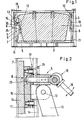
- such a locking device is located in the area of both side parts 3.
- the locking device 5 has an adjustable locking rod 6, which extends transversely to the glass panes 1, the ends of which are connected to actuating devices which are articulated in the area of supports 7 and with a fixing device 8 can be locked in the locking position.
- the actuating devices are designed as knee joint lever systems, the knee joints 9 of which can be bent towards the interior of the transport frame.
- the locking rod 6 is connected to the knee joint lever systems 10, 11 in the region of the knee joints 9.
- the arrangement is also such that the upper lever 10 of the knee joint lever systems 10, 11 is connected with a joint 12 to a bearing block 13 which is guided in a height-adjustable manner in or on the associated support 7.
- the bearing block 13 can be fixed by the fixing device 8 in a predetermined height setting on the support 7.
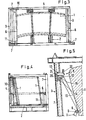
- the supports are designed as hollow supports 7 which have a longitudinal slot 14.
- the bearing blocks 13 are inserted into the associated support 7, wherein they pass through the longitudinal slot 14 with a connecting part 15 for the respective upper lever 10.
- the fixing device is designed as a rack fixing device 8, which consists of a toothed rack 16 arranged in the support 7 and a spring-mounted tooth counter element 17.
- the tooth counter element 17 can be set out of engagement via an actuating device 18 in the exemplary embodiment according to FIG. 2, an eccentric lever 19. From Fig. 2 it can be seen that the rack 16 and the tooth counter-element 17 have a saw toothing, which locks when the tooth counter-element 17 engages only in the upward direction.
- the fixing device is designed as a perforated strip fixing device 8, which consists of a perforated strip 20 arranged in the support 7 or on the support 7 and an associated locking bolt 21 which is mounted in the bearing block 13 and has an actuating device 18 in the form of a sash 22.
- the eccentric lever 19 works on an adjusting bolt 23, by means of which the tooth counter-element 17 can be lifted off the rack 16 against return springs 24.
Claims (6)
Priority Applications (1)
| Application Number | Priority Date | Filing Date | Title |
|---|---|---|---|
| AT87108687T ATE47573T1 (de) | 1986-07-01 | 1987-06-16 | Transportgestell fuer glasscheiben. |
Applications Claiming Priority (2)
| Application Number | Priority Date | Filing Date | Title |
|---|---|---|---|
| DE3621988 | 1986-07-01 | ||
| DE3621988A DE3621988C1 (de) | 1986-07-01 | 1986-07-01 | Transportgestell fuer Glasscheiben |
Publications (2)
| Publication Number | Publication Date |
|---|---|
| EP0257219A1 EP0257219A1 (fr) | 1988-03-02 |
| EP0257219B1 true EP0257219B1 (fr) | 1989-10-25 |
Family
ID=6304105
Family Applications (1)
| Application Number | Title | Priority Date | Filing Date |
|---|---|---|---|
| EP87108687A Expired EP0257219B1 (fr) | 1986-07-01 | 1987-06-16 | Châssis de transport pour plaques de verre |
Country Status (5)
| Country | Link |
|---|---|
| EP (1) | EP0257219B1 (fr) |
| AT (1) | ATE47573T1 (fr) |
| DE (2) | DE3621988C1 (fr) |
| ES (1) | ES2011282B3 (fr) |
| GR (1) | GR3000199T3 (fr) |
Families Citing this family (13)
| Publication number | Priority date | Publication date | Assignee | Title |
|---|---|---|---|---|
| DE8717269U1 (fr) * | 1987-11-29 | 1988-06-01 | Fahrzeugwerk Orthaus Gmbh & Co Kg, 4422 Ahaus, De | |
| DE4003448A1 (de) * | 1990-02-06 | 1991-08-08 | Ver Glaswerke Gmbh | Transportpalette fuer autoglasscheiben |
| DE4119495C2 (de) * | 1991-06-13 | 1997-05-22 | Flachglas Ag | Transportgestell für Glasscheiben, insbesondere Kfz-Glasscheiben |
| FR2740435B1 (fr) * | 1995-10-16 | 1998-01-16 | Ppg Ind Glass Sa | Conteneur destine a recevoir une pile d'articles en feuilles tels que des pare-brises |
| GB2359803B (en) * | 2000-03-02 | 2004-01-14 | Paul Anthony Derry | Supporting articles within a container |
| KR100438200B1 (ko) * | 2003-11-24 | 2004-07-02 | 삼성코닝정밀유리 주식회사 | 디스플레이용 평판유리 포장 콘테이너 및 포장방법 |
| KR100439604B1 (ko) * | 2003-11-24 | 2004-07-12 | 삼성코닝정밀유리 주식회사 | 디스플레이용 평판유리 포장 콘테이너 |
| JP3739382B2 (ja) * | 2003-11-24 | 2006-01-25 | サンスン コールニン プレシシオン ガラス コーポレーション リミテッド | ディスプレイ用平面ガラス板の包装コンテナ |
| JP4756326B2 (ja) * | 2005-06-16 | 2011-08-24 | 日本電気硝子株式会社 | ガラス板の梱包装置 |
| CN103010746A (zh) * | 2011-09-22 | 2013-04-03 | 吉富新能源科技(上海)有限公司 | 一种光伏玻璃镀膜传送压板装置 |
| CN106185322B (zh) * | 2016-07-28 | 2018-09-28 | 彩虹显示器件股份有限公司 | 一种折叠式a型架 |
| CN107814197A (zh) * | 2017-09-14 | 2018-03-20 | 合肥惠科金扬科技有限公司 | 一种多批量amoled液晶屏幕压紧存放装置 |
| CN108945702B (zh) * | 2018-08-03 | 2020-06-16 | 南京中车物流服务有限公司 | 高铁外门系统承载机构通用折叠储运料架 |
Family Cites Families (6)
| Publication number | Priority date | Publication date | Assignee | Title |
|---|---|---|---|---|
| DE1734776U (de) * | 1954-05-07 | 1956-11-29 | Kleber & Co J | Hoehenverstellbarer tisch. |
| DE6601123U (de) * | 1961-10-28 | 1969-02-27 | Kvernelands Fabrikk As | Teleskopische Kupplungsstange, vorzugsweise für ein Dreipunkt aufgehängtes landwirtschaftliches Gerät an Traktoren |
| US3809234A (en) * | 1971-11-08 | 1974-05-07 | Libbey Owens Ford Co | Glass shipping rack |
| US4010849A (en) * | 1975-10-01 | 1977-03-08 | Ppg Industries, Inc. | Nestable article shipping rack having pivotally mounted end restraints |
| DE2735724C2 (de) * | 1977-04-21 | 1985-05-30 | Walter Dr.-Ing. 5100 Aachen Jürgens | Transportgestell für Glasscheiben, insbesondere für Autoglasscheiben |
| DE2905924A1 (de) * | 1979-02-16 | 1980-08-21 | Juergens Walter | Glasscheibentransportgestell |
-
1986
- 1986-07-01 DE DE3621988A patent/DE3621988C1/de not_active Expired
-
1987
- 1987-06-16 DE DE8787108687T patent/DE3760870D1/de not_active Expired
- 1987-06-16 EP EP87108687A patent/EP0257219B1/fr not_active Expired
- 1987-06-16 ES ES87108687T patent/ES2011282B3/es not_active Expired - Lifetime
- 1987-06-16 AT AT87108687T patent/ATE47573T1/de not_active IP Right Cessation
-
1989
- 1989-10-26 GR GR89400200T patent/GR3000199T3/el unknown
Also Published As
| Publication number | Publication date |
|---|---|
| ATE47573T1 (de) | 1989-11-15 |
| DE3621988C1 (de) | 1987-05-14 |
| ES2011282B3 (es) | 1990-01-01 |
| DE3760870D1 (en) | 1989-11-30 |
| EP0257219A1 (fr) | 1988-03-02 |
| GR3000199T3 (en) | 1990-12-31 |
Similar Documents
| Publication | Publication Date | Title |
|---|---|---|
| DE2418765C3 (de) | Fahrzeugsitz | |
| EP0257219B1 (fr) | Châssis de transport pour plaques de verre | |
| DE3040213A1 (de) | Traggestell fuer einen fahrzeugsitz | |
| DE3022741A1 (de) | Federnde aufhaengung fuer einen in laengsrichtung einstellbaren fahrzeugsitz | |
| DE3522285A1 (de) | Fahrzeugsitz | |
| DE1283458B (de) | Sessel mit einer ein- und ausfahrbaren Beinstuetze | |
| EP0670945B1 (fr) | Support comportant une tete demontable | |
| DE3134298C2 (de) | Verstellbarer Fahrzeugsitz | |
| DE3303193A1 (de) | Hoehenverstellbarer tisch, insbesondere fuer bildschirmarbeitsplaetze | |
| DE8027556U1 (de) | Kindersitz | |
| DE3505010A1 (de) | Sicherheitssitz fuer kinder in kraftfahrzeugen | |
| EP0419788B1 (fr) | Appui-pieds réglable pour une disposition des sièges d'un véhicule à moteur | |
| DE2616802A1 (de) | Halter fuer lotrecht regelbare fahrzeugsitze | |
| DE3214849C2 (de) | Verstelleinrichtung für einen Skibindungsbacken | |
| EP1736393A1 (fr) | Chevalet pour matériaux longs | |
| EP0772879A1 (fr) | Faisceau de crayons combustibles assembles a l'aide de tenons | |
| DE4233233C2 (de) | Handhebelpresse | |
| CH647939A5 (en) | Folding table | |
| DE8121177U1 (de) | Sitz, insbesondere kraftfahrzeugsitz | |
| DE4414608A1 (de) | Fahrzeugsitz, insbesondere Kraftfahrzeug-Rücksitz | |
| DE2265374B1 (de) | Hoehen- und Neigungsverstelleinrichtung fuer Fahrzeugsitze | |
| DE4219875A1 (de) | Klappbares Untergestell, insbesondere für einen Tisch zur Verwendung in einem Wohnmobil sowie Möbel mit diesem Untergestell | |
| DE2855915B2 (de) | Sitzmöbel | |
| DE1815381C3 (de) | Kinderbett mit herablaßbarem Seitengitter | |
| DE2417808C3 (de) | Schrankbett mit Gewichtsausgleich |
Legal Events
| Date | Code | Title | Description |
|---|---|---|---|
| PUAI | Public reference made under article 153(3) epc to a published international application that has entered the european phase |
Free format text: ORIGINAL CODE: 0009012 |
|
| AK | Designated contracting states |
Kind code of ref document: A1 Designated state(s): AT BE CH DE ES FR GB GR IT LI LU NL SE |
|
| 17P | Request for examination filed |
Effective date: 19880123 |
|
| 17Q | First examination report despatched |
Effective date: 19890406 |
|
| GRAA | (expected) grant |
Free format text: ORIGINAL CODE: 0009210 |
|
| AK | Designated contracting states |
Kind code of ref document: B1 Designated state(s): AT BE CH DE ES FR GB GR IT LI LU NL SE |
|
| REF | Corresponds to: |
Ref document number: 47573 Country of ref document: AT Date of ref document: 19891115 Kind code of ref document: T |
|
| ITF | It: translation for a ep patent filed |
Owner name: ING. A. GIAMBROCONO & C. S.R.L. |
|
| GBT | Gb: translation of ep patent filed (gb section 77(6)(a)/1977) | ||
| REF | Corresponds to: |
Ref document number: 3760870 Country of ref document: DE Date of ref document: 19891130 |
|
| ET | Fr: translation filed | ||
| REG | Reference to a national code |
Ref country code: GR Ref legal event code: FG4A Free format text: 3000199 |
|
| PLBE | No opposition filed within time limit |
Free format text: ORIGINAL CODE: 0009261 |
|
| STAA | Information on the status of an ep patent application or granted ep patent |
Free format text: STATUS: NO OPPOSITION FILED WITHIN TIME LIMIT |
|
| 26N | No opposition filed | ||
| ITTA | It: last paid annual fee | ||
| PGFP | Annual fee paid to national office [announced via postgrant information from national office to epo] |
Ref country code: GR Payment date: 19930629 Year of fee payment: 7 |
|
| PGFP | Annual fee paid to national office [announced via postgrant information from national office to epo] |
Ref country code: NL Payment date: 19930630 Year of fee payment: 7 |
|
| PGFP | Annual fee paid to national office [announced via postgrant information from national office to epo] |
Ref country code: CH Payment date: 19930712 Year of fee payment: 7 |
|
| PG25 | Lapsed in a contracting state [announced via postgrant information from national office to epo] |
Ref country code: LI Effective date: 19940630 Ref country code: CH Effective date: 19940630 |
|
| EPTA | Lu: last paid annual fee | ||
| PG25 | Lapsed in a contracting state [announced via postgrant information from national office to epo] |
Ref country code: GR Free format text: THE PATENT HAS BEEN ANNULLED BY A DECISION OF A NATIONAL AUTHORITY Effective date: 19941231 |
|
| PG25 | Lapsed in a contracting state [announced via postgrant information from national office to epo] |
Ref country code: NL Effective date: 19950101 |
|
| EAL | Se: european patent in force in sweden |
Ref document number: 87108687.2 |
|
| NLV4 | Nl: lapsed or anulled due to non-payment of the annual fee | ||
| REG | Reference to a national code |
Ref country code: CH Ref legal event code: PL |
|
| REG | Reference to a national code |
Ref country code: GR Ref legal event code: MM2A Free format text: 3000199 |
|
| PGFP | Annual fee paid to national office [announced via postgrant information from national office to epo] |
Ref country code: GB Payment date: 19960531 Year of fee payment: 10 |
|
| PGFP | Annual fee paid to national office [announced via postgrant information from national office to epo] |
Ref country code: FR Payment date: 19960614 Year of fee payment: 10 |
|
| PGFP | Annual fee paid to national office [announced via postgrant information from national office to epo] |
Ref country code: SE Payment date: 19960619 Year of fee payment: 10 Ref country code: AT Payment date: 19960619 Year of fee payment: 10 |
|
| PGFP | Annual fee paid to national office [announced via postgrant information from national office to epo] |
Ref country code: BE Payment date: 19960621 Year of fee payment: 10 |
|
| PGFP | Annual fee paid to national office [announced via postgrant information from national office to epo] |
Ref country code: ES Payment date: 19960628 Year of fee payment: 10 |
|
| PGFP | Annual fee paid to national office [announced via postgrant information from national office to epo] |
Ref country code: LU Payment date: 19960630 Year of fee payment: 10 |
|
| PG25 | Lapsed in a contracting state [announced via postgrant information from national office to epo] |
Ref country code: LU Free format text: LAPSE BECAUSE OF NON-PAYMENT OF DUE FEES Effective date: 19970616 Ref country code: GB Free format text: LAPSE BECAUSE OF NON-PAYMENT OF DUE FEES Effective date: 19970616 Ref country code: AT Effective date: 19970616 |
|
| PG25 | Lapsed in a contracting state [announced via postgrant information from national office to epo] |
Ref country code: SE Effective date: 19970617 Ref country code: ES Free format text: LAPSE BECAUSE OF NON-PAYMENT OF DUE FEES Effective date: 19970617 |
|
| PG25 | Lapsed in a contracting state [announced via postgrant information from national office to epo] |
Ref country code: BE Effective date: 19970630 |
|
| BERE | Be: lapsed |
Owner name: FLACHGLAS A.G. Effective date: 19970630 |
|
| GBPC | Gb: european patent ceased through non-payment of renewal fee |
Effective date: 19970616 |
|
| PG25 | Lapsed in a contracting state [announced via postgrant information from national office to epo] |
Ref country code: FR Free format text: LAPSE BECAUSE OF NON-PAYMENT OF DUE FEES Effective date: 19980227 |
|
| EUG | Se: european patent has lapsed |
Ref document number: 87108687.2 |
|
| PGFP | Annual fee paid to national office [announced via postgrant information from national office to epo] |
Ref country code: DE Payment date: 19980331 Year of fee payment: 12 |
|
| REG | Reference to a national code |
Ref country code: FR Ref legal event code: ST |
|
| REG | Reference to a national code |
Ref country code: FR Ref legal event code: ST |
|
| PG25 | Lapsed in a contracting state [announced via postgrant information from national office to epo] |
Ref country code: DE Free format text: LAPSE BECAUSE OF NON-PAYMENT OF DUE FEES Effective date: 20000503 |
|
| REG | Reference to a national code |
Ref country code: ES Ref legal event code: FD2A Effective date: 20000503 |
|
| PG25 | Lapsed in a contracting state [announced via postgrant information from national office to epo] |
Ref country code: IT Free format text: LAPSE BECAUSE OF NON-PAYMENT OF DUE FEES;WARNING: LAPSES OF ITALIAN PATENTS WITH EFFECTIVE DATE BEFORE 2007 MAY HAVE OCCURRED AT ANY TIME BEFORE 2007. THE CORRECT EFFECTIVE DATE MAY BE DIFFERENT FROM THE ONE RECORDED. Effective date: 20050616 |