EP0257219B1 - Transport equipment for glass panes - Google Patents
Transport equipment for glass panes Download PDFInfo
- Publication number
- EP0257219B1 EP0257219B1 EP87108687A EP87108687A EP0257219B1 EP 0257219 B1 EP0257219 B1 EP 0257219B1 EP 87108687 A EP87108687 A EP 87108687A EP 87108687 A EP87108687 A EP 87108687A EP 0257219 B1 EP0257219 B1 EP 0257219B1
- Authority
- EP
- European Patent Office
- Prior art keywords
- support
- fixing mechanism
- transport frame
- locking
- bearing block
- Prior art date
- Legal status (The legal status is an assumption and is not a legal conclusion. Google has not performed a legal analysis and makes no representation as to the accuracy of the status listed.)
- Expired
Links
Images
Classifications
-
- B—PERFORMING OPERATIONS; TRANSPORTING
- B65—CONVEYING; PACKING; STORING; HANDLING THIN OR FILAMENTARY MATERIAL
- B65D—CONTAINERS FOR STORAGE OR TRANSPORT OF ARTICLES OR MATERIALS, e.g. BAGS, BARRELS, BOTTLES, BOXES, CANS, CARTONS, CRATES, DRUMS, JARS, TANKS, HOPPERS, FORWARDING CONTAINERS; ACCESSORIES, CLOSURES, OR FITTINGS THEREFOR; PACKAGING ELEMENTS; PACKAGES
- B65D85/00—Containers, packaging elements or packages, specially adapted for particular articles or materials
- B65D85/30—Containers, packaging elements or packages, specially adapted for particular articles or materials for articles particularly sensitive to damage by shock or pressure
- B65D85/48—Containers, packaging elements or packages, specially adapted for particular articles or materials for articles particularly sensitive to damage by shock or pressure for glass sheets
Definitions
- the invention relates generically to a transport frame for glass panes, with bottom, side parts, back part and locking device for the side locking of glass panes set in the region of at least one side part, the locking device having an adjustable locking rod running transversely to the glass panes, at least one of which End is connected to an actuating device which is articulated in the area of the support and can be fixed in the locking position with a fixing device.
- the bottom, the side parts and the back part can be designed as a frame construction.
- the transport frame can be collapsible, it can also be set up so that several transport frames can be inserted into one another in the emptied state.
- adjusting devices are provided in the form of rockers, which work with one-armed, more or less obliquely upward-pointing levers which are rigidly connected to both ends of the locking rod and in the area of the floor to the Supports are articulated, the assembly of the swing arms and the locking rod is briefly referred to as a swing arm.
- This unit is freely movable from an upper position, which can be fixed by tying it to the side parts, under the influence of gravity.
- a fixing rod is used to fix the unit in the swiveled-out position with the locking rod resting against the glass panes on the front, which is inserted into the V-shaped throats between the rockers and the supports, follows the influence of gravity and is held in the throats by self-locking as long as the Angle of the throats is not too large and the coefficient of friction is not affected by moisture, contaminants or the like. Since the angle of the throats must not become too large due to the self-locking condition, the travel of the locking rod is limited. If one also takes into account the great weight of the set glass panes and the associated transport stresses, a fixing rod arranged in this way does not offer the guarantee of a defined fixing and thus does not provide the required functional reliability.
- the known transport frame can not be used easily for glass panes that differ considerably in size because of the short travel. In terms of operation, there are difficulties because of the manipulation of the fixing rod that is required at least when the locking rod is released.
- Devices for locking with a rack or perforated strip are known per se from DE-GM 17 34 776 or from DE-GM 66 01 123.
- the object of the invention is to increase the functional reliability of a generic transport frame, to simplify the operating technology and, in addition, to increase the functionally reliable travel path for the locking rod.
- the invention teaches that the actuating device is designed as a knee joint lever system, the knee joint of which can be flexed towards the interior of the transport frame, that one end of the locking rod is connected in the region of the knee joint, that the respective upper lever of the knee joint lever system has a joint is connected to a bearing block, which is guided in a height-adjustable manner on the associated support, and. that the bearing block can be fixed in a predetermined height setting by the fixing device.
- the invention is based on the finding that a free swing movement of the locking rod in relation to the fixing of the locking rod on the glass panes leads to difficulties and works with a positive guidance of the locking rod. This makes it possible to press the locking rod against the set glass panes and to fix it securely and to loosen the fixing again in a simple manner, so that the locking rod can be lifted up or raised. The glass panes are then easily accessible for the purpose of removal.
- a preferred embodiment of the invention which is characterized by simplicity, is characterized in that the support is designed as a hollow support which has a longitudinal slot, and that the bearing block is inserted into the associated support and with a connecting part for the upper lever, the longitudinal slot grasped.
- the fixing device can be designed as a rack fixing device, which consists of a rack arranged in the support or on the support and a spring-mounted tooth counter element, the tooth counter element via an actuating device, for. B. an eccentric lever or sash can be set out of engagement.
- a preferred embodiment of the invention is characterized in that the toothed rack and the counter-tooth element have sawtooth teeth which lock only in the upward direction when the counter-tooth element engages.
- the tooth pitch can easily be selected to be sufficiently fine.
- the fixing device in which the locking rod automatically returns to its starting position after loosening the fixing device, is characterized in that the fixing device works together with a gas spring which is accommodated in the support and is connected with its adjusting rod to the bearing block, and that Gas spring compressible as well by a downward movement of the locking rod can be pushed back into its starting position by releasing its fixing device.
- the technology can be implemented that is common for chairs and tables that are height adjustable by means of gas springs.
- the transport frame according to the invention is characterized by high functional reliability and ease of use.
- the travel for the locking rod can be set up for a very long travel.
- such a locking device is located in the area of both side parts 3.
- the locking device 5 has an adjustable locking rod 6, which extends transversely to the glass panes 1, the ends of which are connected to actuating devices which are articulated in the area of supports 7 and with a fixing device 8 can be locked in the locking position.
- the actuating devices are designed as knee joint lever systems, the knee joints 9 of which can be bent towards the interior of the transport frame.
- the locking rod 6 is connected to the knee joint lever systems 10, 11 in the region of the knee joints 9.
- the arrangement is also such that the upper lever 10 of the knee joint lever systems 10, 11 is connected with a joint 12 to a bearing block 13 which is guided in a height-adjustable manner in or on the associated support 7.
- the bearing block 13 can be fixed by the fixing device 8 in a predetermined height setting on the support 7.
- the supports are designed as hollow supports 7 which have a longitudinal slot 14.
- the bearing blocks 13 are inserted into the associated support 7, wherein they pass through the longitudinal slot 14 with a connecting part 15 for the respective upper lever 10.
- the fixing device is designed as a rack fixing device 8, which consists of a toothed rack 16 arranged in the support 7 and a spring-mounted tooth counter element 17.
- the tooth counter element 17 can be set out of engagement via an actuating device 18 in the exemplary embodiment according to FIG. 2, an eccentric lever 19. From Fig. 2 it can be seen that the rack 16 and the tooth counter-element 17 have a saw toothing, which locks when the tooth counter-element 17 engages only in the upward direction.
- the fixing device is designed as a perforated strip fixing device 8, which consists of a perforated strip 20 arranged in the support 7 or on the support 7 and an associated locking bolt 21 which is mounted in the bearing block 13 and has an actuating device 18 in the form of a sash 22.
- the eccentric lever 19 works on an adjusting bolt 23, by means of which the tooth counter-element 17 can be lifted off the rack 16 against return springs 24.
Abstract
Description
Die Erfindung bezieht sich gattungsgemäß auf ein Transportgestell für Glasscheiben, - mit Boden, Seitenteilen, Rückenteil und Arretiereinrichtung für die Seitenarretierung eingestellter Glasscheiben im Bereich von zumindest einem Seitenteil, wobei die Arretiereinrichtung eine quer zu den Glasscheiben verlaufende, verstellbare Arretierstange aufweist, von der zumindest ein Ende an eine Stelleinrichtung angeschlossen ist, die im Bereich der Stütze gelenkig gelagert und mit einer Festsetzeinrichtung in Arretierstellung festsetzbar ist. Der Boden, die Seitenteile und das Rückenteil können als Rahmenkonstruktion ausgeführt sein. Das Transportgestell kann zusammenklappbar sein, es kann auch so eingerichtet sein, daß mehrere Transportgestelle im entleerten Zustand ineinandersetzbar sind.The invention relates generically to a transport frame for glass panes, with bottom, side parts, back part and locking device for the side locking of glass panes set in the region of at least one side part, the locking device having an adjustable locking rod running transversely to the glass panes, at least one of which End is connected to an actuating device which is articulated in the area of the support and can be fixed in the locking position with a fixing device. The bottom, the side parts and the back part can be designed as a frame construction. The transport frame can be collapsible, it can also be set up so that several transport frames can be inserted into one another in the emptied state.
Bei dem bekannten gattungsgemäßen Transportgestell (OS-27 35 724) sind Stelleinrichtungen in Form von Schwingen vorgesehen, die mit einarmigen, mehr oder weniger schräg nach oben weisenden Hebeln arbeiten, die mit beiden Enden der Arretierstange starr verbunden sind und im Bereich des Bodens an die Stützen angelenkt sind, auch das Aggregat aus den Schwingen und der Arretierstange wird kurz als Schwinge bezeichnet. Dieses Aggregat ist aus einer oberen, durch Festbinden an den Seitenteilen fixierbaren Stellung unter dem Einfluß der Schwerkraft frei beweglich. Zum Festsetzen des Aggregates in abgeschwenkter Stellung mit an den Glasscheiben stirnseitig anliegender Arretierstange dient eine Festlegestange, die in die V-förmigen Kehlen zwischen den Schwingen und den Stützen eingelegt wird, dem Einfluß der Schwerkraft folgt und durch Selbsthemmung in den Kehlen festgehalten wird, solange der Winkel der Kehlen nicht zu groß ist und der Reibungskoeffizient nicht durch Feuchtigkeit, Verunreinigungen oder dergleichen beeinflußt ist. Da der Winkel der Kehlen wegen der Selbsthemmungsbedingung nicht zu groß werden darf, ist der Stellweg der Arretierstange beschränkt. Berücksichtigt man ferner das große Gewicht der eingestellten Glasscheiben und die damit verbundenen Transportbeanspruchungen, so bietet eine derartig angeordnete Festlegestange nicht die Gewähr einer definierten Festsetzung und damit nicht die erforderliche Funktionssicherheit. Das bekannte Transportgestell kann wegen des geringen Stellweges nicht ohne weiteres für Glasscheiben verwendet werden, die sich in der Größe beachtlich unterscheiden. Bedienungstechnisch bestehen Schwierigkeiten, wegen der zumindest beim Lösen der Arretierstange erforderlichen Manipulation der Festlegestange.In the known generic transport frame (OS-27 35 724) adjusting devices are provided in the form of rockers, which work with one-armed, more or less obliquely upward-pointing levers which are rigidly connected to both ends of the locking rod and in the area of the floor to the Supports are articulated, the assembly of the swing arms and the locking rod is briefly referred to as a swing arm. This unit is freely movable from an upper position, which can be fixed by tying it to the side parts, under the influence of gravity. A fixing rod is used to fix the unit in the swiveled-out position with the locking rod resting against the glass panes on the front, which is inserted into the V-shaped throats between the rockers and the supports, follows the influence of gravity and is held in the throats by self-locking as long as the Angle of the throats is not too large and the coefficient of friction is not affected by moisture, contaminants or the like. Since the angle of the throats must not become too large due to the self-locking condition, the travel of the locking rod is limited. If one also takes into account the great weight of the set glass panes and the associated transport stresses, a fixing rod arranged in this way does not offer the guarantee of a defined fixing and thus does not provide the required functional reliability. The known transport frame can not be used easily for glass panes that differ considerably in size because of the short travel. In terms of operation, there are difficulties because of the manipulation of the fixing rod that is required at least when the locking rod is released.
Vorrichtungen zum Arretieren mit Zahnstange bzw. Lochleiste sind an sich aus dem DE-GM 17 34 776 bzw. aus dem DE-GM 66 01 123 bekannt.Devices for locking with a rack or perforated strip are known per se from DE-GM 17 34 776 or from DE-GM 66 01 123.
Der Erfindung liegt die Aufgabe zugrunde, bei einem gattungsgemäßen Tansportgestell die Funktionssicherheit zu erhöhen, die Bedienungstechnik zu vereinfachen und darüber hinaus den funktionssicheren Stellweg für die Arretierstange zu vergrößern.The object of the invention is to increase the functional reliability of a generic transport frame, to simplify the operating technology and, in addition, to increase the functionally reliable travel path for the locking rod.
Zur Lösung dieser Aufgabe lehrt die Erfindung, daß die Stelleinrichtung als Kniegelenk-Hebelsystem ausgeführt ist, dessen Kniegelenk zum Transportgestellinnenraum hin beugbar ist, daß ein Ende der Arretierstange im Bereich des Kniegelenks angeschlossen ist, daß der jeweils obere Hebel des Kniegelenk-Hebelsystems mit einem Gelenk an einem Lagerblock angeschlossen ist, der an der zugeordneten Stütze höhenverstellbar geführt ist, und . daß der Lagerblock durch die Festsetzeinrichtung in vorgegebener Höheneinstellung festsetzbar ist. - Die Erfindung geht von der Erkenntnis aus, daß eine freie Schwingenbewegung der Arretierstange in bezug auf die Festsetzung der Arretierstange an den Glasscheiben zu Schwierigkeiten führt und arbeitet mit einer Zwangsführung der Arretierstange. Diese erlaubt es, die Arretierstange gegen die eingestellten Glasscheiben anzudrücken und sicher festzusetzen und die Festsetzung auch auf einfache Weise wieder zu lösen, so daß die Arretierstange hochgenommen oder hochgefahren werden kann. Die Glasscheiben sind dann insoweit zum Zwecke der Entnahme leicht zugänglich.To achieve this object, the invention teaches that the actuating device is designed as a knee joint lever system, the knee joint of which can be flexed towards the interior of the transport frame, that one end of the locking rod is connected in the region of the knee joint, that the respective upper lever of the knee joint lever system has a joint is connected to a bearing block, which is guided in a height-adjustable manner on the associated support, and. that the bearing block can be fixed in a predetermined height setting by the fixing device. - The invention is based on the finding that a free swing movement of the locking rod in relation to the fixing of the locking rod on the glass panes leads to difficulties and works with a positive guidance of the locking rod. This makes it possible to press the locking rod against the set glass panes and to fix it securely and to loosen the fixing again in a simple manner, so that the locking rod can be lifted up or raised. The glass panes are then easily accessible for the purpose of removal.
Im einzelnen bestehen im Rahmen der Patentansprüche mehrere Möglichkeiten der weiteren Ausbildung und Gestaltung. Eine bevorzugte Ausführungsform der Erfindung, die sich durch Einfachheit auszeichnet, ist dadurch gekennzeichnet, daß die Stütze als Hohlstütze ausgeführt ist, die einen Längsschlitz aufweist, und daß der Lagerblock in die zugeordnete Stütze eingesetzt ist sowie mit einem Anschlußteil für den jeweils oberen Hebel den Längsschlitz durchfaßt.There are several options for further training and design within the scope of the claims. A preferred embodiment of the invention, which is characterized by simplicity, is characterized in that the support is designed as a hollow support which has a longitudinal slot, and that the bearing block is inserted into the associated support and with a connecting part for the upper lever, the longitudinal slot grasped.
Auch bezüglich der Festsetzeinrichtung bestehen zur Weiterbildung der Erfindung mehrere Möglichkeiten. So kann die Festsetzeinrichtung als eine Zahnstangenfestsetzeinrichtung ausgeführt sein, die aus einer in der Stütze oder an der Stütze angeordneten Zahnstange und einem federnd gelagerten Zahngegenelement besteht, wobei das Zahngegenelement über eine Betätigungseinrichtung, z. B. einen Exzenterhebel oder Vorreiber, außer Eingriff stellbar ist. Insoweit ist eine bevorzugte Ausführungsform der Erfindung dadurch gekennzeichnet, daß die Zahnstange und das Zahngegenelement eine Sägezahnverzahnung aufweisen, die bei Eingriff des Zahngegenelementes nur in Aufwärtsrichtung sperrt. Die Zahnteilung kann ohne weiteres ausreichend fein gewählt werden. Es besteht aber auch die Möglichkeit, die Festsetzeinrichtung als eine Lochleisten-Festsetzeinrichtung mit möglichst feiner Lochteilung auszuführen, die aus einer in der Stütze oder an der Stütze angeordneten Lochleiste und einem zugeordneten Arretierbolzen besteht, der in dem Lagerblock gelagert ist und eine Betätigungseinrichtung, z. B. einen Vorreiber aufweist. Eine weitere Ausführungsform der Erfindung, bei der die Arretierstange nach Lösen der Festsetzeinrichtung automatisch in ihre Ausgangsstellung zurückkehrt, ist dadurch gekennzeichnet, daß die Festsetzeinrichtung mit einer Gasfeder zusammenarbeitet, die in der Stütze untergebracht sowie mit ihrer Stellstange an den Lagerblock angeschlossen ist, und daß die Gasfeder durch eine Abwärtsbewegung der Arretierstange zusammendrückbar sowie durch Lösen ihrer Festsetzeinrichtung in ihre Ausgangsstellung zurückdrückbar ist. Im Detail kann dabei die Technologie verwirklicht werden, die bei mittels Gasfeder höhenverstellbaren Stühlen und Tischen gebräuchlich ist.There are also several possibilities for developing the invention with regard to the fixing device. Thus, the fixing device can be designed as a rack fixing device, which consists of a rack arranged in the support or on the support and a spring-mounted tooth counter element, the tooth counter element via an actuating device, for. B. an eccentric lever or sash can be set out of engagement. In this respect, a preferred embodiment of the invention is characterized in that the toothed rack and the counter-tooth element have sawtooth teeth which lock only in the upward direction when the counter-tooth element engages. The tooth pitch can easily be selected to be sufficiently fine. But there is also the possibility of performing the fixing device as a perforated strip fixing device with the finest possible hole division, which consists of a perforated strip arranged in the support or on the support and an associated locking bolt which is mounted in the bearing block and an actuating device, for. B. has a sash. Another embodiment of the invention, in which the locking rod automatically returns to its starting position after loosening the fixing device, is characterized in that the fixing device works together with a gas spring which is accommodated in the support and is connected with its adjusting rod to the bearing block, and that Gas spring compressible as well by a downward movement of the locking rod can be pushed back into its starting position by releasing its fixing device. In detail, the technology can be implemented that is common for chairs and tables that are height adjustable by means of gas springs.
Das erfindungsgemäße Transportgestell zeichnet sich durch hohe Funktionssicherheit und bedienungstechnische Einfachheit aus. Der Stellweg für die Arretierstange kann für einen sehr großen Stellweg funktionssicher eingerichtet werden.The transport frame according to the invention is characterized by high functional reliability and ease of use. The travel for the locking rod can be set up for a very long travel.
Im folgenden wird die Erfindung anhand einer lediglich ein Ausführungsbeispiel darstellenden Zeichnung ausführlicher erläutert. Es zeigen in schematischer Darstellung.
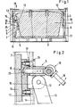
- Fig. 1 die Ansicht eines erfindungsgemäßen Transportgestells, teilweise aufgebrochen,
- Fig. 2 in gegenüber der Fig. 1 wesentlich vergrößertem Maßstab den Ausschnitt A aus dem Gegenstand nach Fig. 1, aufgeschnitten, in vergrößertem Maßstab,
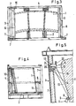
- Fig. 3 eine Draufsicht auf den Gegenstand nach Fig.1,
- Fig. 4 teilweise im Schnitt eine Seitenansicht des Gegenstandes der Fig. 1 und
- Fig. 5 entsprechend der Fig. 2 einen Ausschnitt aus einer anderen Ausführungsform eines erfindungsgemäßen Transportgestells.
- 1 shows the view of a transport frame according to the invention, partially broken away,
- 2 in a significantly enlarged scale compared to FIG. 1, section A from the object according to FIG. 1, cut open, on an enlarged scale,
- 3 shows a plan view of the object according to FIG. 1,
- Fig. 4 is a partial side view of the object of FIGS. 1 and
- Fig. 5 corresponding to Fig. 2 shows a detail from another embodiment of a transport frame according to the invention.
Das in den Figuren dargestellte Transportgestell ist für Glasscheiben 1 bestimmt. In den Fig. 1 sowie 3 und 4 sind eingestellte Glasscheiben 1 angedeutet. Zum grundsätzlichen Aufbau des Transportgestells gehören
- ein
Boden 2, Seitenteile 3- ein
Rückenteil 4 und - eine
Arretiereinrichtung 5 für die Seitenarretierung dereingestellten Glasscheiben 1.
- a
floor 2, -
Side parts 3 - a
back part 4 and - a
locking device 5 for the side locking of theset glass panes 1.
Im Ausführungsbeispiel findet sich eine solche Arretiereinrichtung im Bereich beider Seitenteile 3. Die Arretiereinrichtung 5 weist eine quer zu den Glasscheiben 1 verlaufende verstellbare Arretierstange 6 auf, deren Enden an Stelleinrichtungen angeschlossen sind, die im Bereich von Stützen 7 gelenkig gelagert sind und mit einer Festsetzeinrichtung 8 in Arretierstellung festsetzbar sind.In the exemplary embodiment, such a locking device is located in the area of both
Die Stelleinrichtungen sind als Kniegelenk-Hebelsysteme ausgeführt, deren Kniegelenke 9 zum Transportgestellinnenraum hin beugbar sind. Dazu wird auf eine vergleichende Betrachtung der linken und rechten Seite von Fig. 1 verwiesen. Die Arretierstange 6 ist im Bereich der Kniegelenke 9 an die Kniegelenk-Hebelsysteme 10, 11 angeschlossen. Die Anordnung ist fernerhin so getroffen, daß der jeweils obere Hebel 10 der Kniegelenk-Hebelsysteme 10, 11 mit einem Gelenk 12 an einen Lagerblock 13 angeschlossen ist, der in der oder an der zugeordneten Stütze 7 höhenverstellbar geführt ist. Der Lagerblock 13 ist durch die Festsetzeinrichtung 8 in vorgegebener Höheneinstellung an der Stütze 7 festsetzbar. Im Ausführungsbeispiel und nach bevorzugter Ausführungsform der Erfindung sind die Stützen als Hohlstützen 7 ausgeführt, die einen Längsschlitz 14 aufweisen. Die Lagerblöcke 13 sind in die zugeordnete Stütze 7 eingesetzt, wobei sie mit einem Anschlußteil 15 für den jeweils oberen Hebel 10 den Längsschlitz 14 durchfassen.The actuating devices are designed as knee joint lever systems, the
Im Ausführungsbeispiel nach den Fig. 1 bis 4 ist die Festsetzeinrichtung als eine Zahnstangenfestsetzeinrichtung 8 ausgeführt, die aus einer in der Stütze 7 angeordneten Zahnstange 16 und einem federnd gelagerten Zahngegenelement 17 besteht. Das Zahngegenelement 17 ist über eine Betätigungseinrichtung 18 im Ausführungsbeispiel nach Fig. 2 einen Exzenterhebel 19, außer Eingriff stellbar. Aus der Fig. 2 entnimmt man, daß die Zahnstange 16 und das Zahngegenelement 17 eine Sägezahnverzahnung aufweisen, die bei Eingriff des Zahngegenelementes 17 nur in Aufwärtsrichtung sperrt.In the exemplary embodiment according to FIGS. 1 to 4, the fixing device is designed as a
Die Fig. 5 zeigt eine Ausführungsform, bei der die Festsetzeinrichtung als eine Lochleisten-Festsetzeinrichtung 8 ausgeführt ist, die aus einer in der Stütze 7 oder an der Stütze 7 angeordneten Lochleiste 20 und einem zugeordneten Arretierbolzen 21 besteht, der in dem Lagerblock 13 gelagert ist und eine Betätigungseinrichtung 18 in Form eines Vorreibers 22 aufweist. Aus der Fig. 2 ist zu entnehmen, daß der Exzenterhebel 19 auf einen Stellbolzen 23 arbeitet, über den das Zahngegenelement 17 entgegen Rückstellfedern 24 von der Zahnstange 16 abhebbar ist.5 shows an embodiment in which the fixing device is designed as a perforated
Claims (6)
Priority Applications (1)
| Application Number | Priority Date | Filing Date | Title |
|---|---|---|---|
| AT87108687T ATE47573T1 (en) | 1986-07-01 | 1987-06-16 | TRANSPORT FRAME FOR GLASS PANES. |
Applications Claiming Priority (2)
| Application Number | Priority Date | Filing Date | Title |
|---|---|---|---|
| DE3621988A DE3621988C1 (en) | 1986-07-01 | 1986-07-01 | Transport frame for glass panes |
| DE3621988 | 1986-07-01 |
Publications (2)
| Publication Number | Publication Date |
|---|---|
| EP0257219A1 EP0257219A1 (en) | 1988-03-02 |
| EP0257219B1 true EP0257219B1 (en) | 1989-10-25 |
Family
ID=6304105
Family Applications (1)
| Application Number | Title | Priority Date | Filing Date |
|---|---|---|---|
| EP87108687A Expired EP0257219B1 (en) | 1986-07-01 | 1987-06-16 | Transport equipment for glass panes |
Country Status (5)
| Country | Link |
|---|---|
| EP (1) | EP0257219B1 (en) |
| AT (1) | ATE47573T1 (en) |
| DE (2) | DE3621988C1 (en) |
| ES (1) | ES2011282B3 (en) |
| GR (1) | GR3000199T3 (en) |
Families Citing this family (13)
| Publication number | Priority date | Publication date | Assignee | Title |
|---|---|---|---|---|
| DE8717269U1 (en) * | 1987-11-29 | 1988-06-01 | Fahrzeugwerk Orthaus Gmbh & Co Kg, 4422 Ahaus, De | |
| DE4003448A1 (en) * | 1990-02-06 | 1991-08-08 | Ver Glaswerke Gmbh | TRANSPORT PALLET FOR CAR GLASS PANELS |
| DE4119495C2 (en) * | 1991-06-13 | 1997-05-22 | Flachglas Ag | Transport frame for glass panes, in particular automotive glass panes |
| FR2740435B1 (en) * | 1995-10-16 | 1998-01-16 | Ppg Ind Glass Sa | CONTAINER FOR RECEIVING A STACK OF SHEET ARTICLES SUCH AS WINDSHIELDS |
| GB2359803B (en) * | 2000-03-02 | 2004-01-14 | Paul Anthony Derry | Supporting articles within a container |
| KR100438200B1 (en) * | 2003-11-24 | 2004-07-02 | 삼성코닝정밀유리 주식회사 | Packing container and packing method for flat display glass |
| JP3739382B2 (en) * | 2003-11-24 | 2006-01-25 | サンスン コールニン プレシシオン ガラス コーポレーション リミテッド | Packaging container for flat glass plate for display |
| KR100439604B1 (en) * | 2003-11-24 | 2004-07-12 | 삼성코닝정밀유리 주식회사 | Packing container for flat display glass |
| JP4756326B2 (en) * | 2005-06-16 | 2011-08-24 | 日本電気硝子株式会社 | Glass plate packing equipment |
| CN103010746A (en) * | 2011-09-22 | 2013-04-03 | 吉富新能源科技(上海)有限公司 | Photovoltaic glass coating conveying pressing plate device |
| CN106185322B (en) * | 2016-07-28 | 2018-09-28 | 彩虹显示器件股份有限公司 | A kind of collapsible A type frame |
| CN107814197A (en) * | 2017-09-14 | 2018-03-20 | 合肥惠科金扬科技有限公司 | A kind of more batch AMOLED LCD screens compress storing unit |
| CN108945702B (en) * | 2018-08-03 | 2020-06-16 | 南京中车物流服务有限公司 | Universal folding material storage and transportation rack for bearing mechanism of high-speed rail outer door system |
Family Cites Families (6)
| Publication number | Priority date | Publication date | Assignee | Title |
|---|---|---|---|---|
| DE1734776U (en) * | 1954-05-07 | 1956-11-29 | Kleber & Co J | ADJUSTABLE TABLE. |
| DE6601123U (en) * | 1961-10-28 | 1969-02-27 | Kvernelands Fabrikk As | Telescopic coupling rod, preferably for a three-point suspended agricultural device on tractors |
| US3809234A (en) * | 1971-11-08 | 1974-05-07 | Libbey Owens Ford Co | Glass shipping rack |
| US4010849A (en) * | 1975-10-01 | 1977-03-08 | Ppg Industries, Inc. | Nestable article shipping rack having pivotally mounted end restraints |
| DE2735724C2 (en) * | 1977-04-21 | 1985-05-30 | Walter Dr.-Ing. 5100 Aachen Jürgens | Transport frame for glass panes, in particular for car glass panes |
| DE2905924A1 (en) * | 1979-02-16 | 1980-08-21 | Juergens Walter | Transporter frame for glass panes - has automatic locking device between arm and upright supports joined to form frame |
-
1986
- 1986-07-01 DE DE3621988A patent/DE3621988C1/en not_active Expired
-
1987
- 1987-06-16 DE DE8787108687T patent/DE3760870D1/en not_active Expired
- 1987-06-16 EP EP87108687A patent/EP0257219B1/en not_active Expired
- 1987-06-16 ES ES87108687T patent/ES2011282B3/en not_active Expired - Lifetime
- 1987-06-16 AT AT87108687T patent/ATE47573T1/en not_active IP Right Cessation
-
1989
- 1989-10-26 GR GR89400200T patent/GR3000199T3/en unknown
Also Published As
| Publication number | Publication date |
|---|---|
| ATE47573T1 (en) | 1989-11-15 |
| DE3760870D1 (en) | 1989-11-30 |
| GR3000199T3 (en) | 1990-12-31 |
| DE3621988C1 (en) | 1987-05-14 |
| EP0257219A1 (en) | 1988-03-02 |
| ES2011282B3 (en) | 1990-01-01 |
Similar Documents
| Publication | Publication Date | Title |
|---|---|---|
| DE2418765C3 (en) | Vehicle seat | |
| EP0257219B1 (en) | Transport equipment for glass panes | |
| DE3040213A1 (en) | CARRIER FOR A VEHICLE SEAT | |
| DE3022741A1 (en) | SPRING SUSPENSION FOR A VEHICLE SEAT ADJUSTABLE IN THE LONG DIRECTION | |
| DE3522285A1 (en) | VEHICLE SEAT | |
| EP1492702A1 (en) | Headrest for a seat | |
| DE1283458B (en) | Armchair with a retractable and extendable leg support | |
| DE2653889C2 (en) | Inclination adjustment device for vehicle seats | |
| EP0670945B1 (en) | Upright with detachable head | |
| DE3134298C2 (en) | Adjustable vehicle seat | |
| DE3303193A1 (en) | Vertically adjustable table, in particular for video workstations | |
| DE8027556U1 (en) | CHILD SEAT | |
| DE3505010A1 (en) | Child's car safety seat | |
| EP0419788B1 (en) | Adjustable footrest for a seat arrangement of a motor vehicle | |
| DE2616802A1 (en) | BRACKET FOR PLATFORM ADJUSTABLE VEHICLE SEATS | |
| DE3214849C2 (en) | Adjustment device for a ski binding jaw | |
| EP1736393A1 (en) | Supporting trestle for long materials | |
| DE4233233C2 (en) | Hand lever press | |
| DE8121177U1 (en) | SEAT, IN PARTICULAR MOTOR VEHICLE SEAT | |
| DE4414608A1 (en) | Vehicle seat, esp for rear seat | |
| DE2265374B1 (en) | Height and inclination adjustment device for vehicle seats | |
| DE4219875A1 (en) | Folding underneath frame for table, especially in caravan - has uprights each consisting of top, middle and bottom part, with sleeves, locking pins, stop, and two hinges. | |
| DE2855915B2 (en) | Seating | |
| DE1815381C3 (en) | Children's bed with lowerable side rails | |
| DE2417808C3 (en) | Wall bed with counterbalance |
Legal Events
| Date | Code | Title | Description |
|---|---|---|---|
| PUAI | Public reference made under article 153(3) epc to a published international application that has entered the european phase |
Free format text: ORIGINAL CODE: 0009012 |
|
| AK | Designated contracting states |
Kind code of ref document: A1 Designated state(s): AT BE CH DE ES FR GB GR IT LI LU NL SE |
|
| 17P | Request for examination filed |
Effective date: 19880123 |
|
| 17Q | First examination report despatched |
Effective date: 19890406 |
|
| GRAA | (expected) grant |
Free format text: ORIGINAL CODE: 0009210 |
|
| AK | Designated contracting states |
Kind code of ref document: B1 Designated state(s): AT BE CH DE ES FR GB GR IT LI LU NL SE |
|
| REF | Corresponds to: |
Ref document number: 47573 Country of ref document: AT Date of ref document: 19891115 Kind code of ref document: T |
|
| ITF | It: translation for a ep patent filed |
Owner name: ING. A. GIAMBROCONO & C. S.R.L. |
|
| GBT | Gb: translation of ep patent filed (gb section 77(6)(a)/1977) | ||
| REF | Corresponds to: |
Ref document number: 3760870 Country of ref document: DE Date of ref document: 19891130 |
|
| ET | Fr: translation filed | ||
| REG | Reference to a national code |
Ref country code: GR Ref legal event code: FG4A Free format text: 3000199 |
|
| PLBE | No opposition filed within time limit |
Free format text: ORIGINAL CODE: 0009261 |
|
| STAA | Information on the status of an ep patent application or granted ep patent |
Free format text: STATUS: NO OPPOSITION FILED WITHIN TIME LIMIT |
|
| 26N | No opposition filed | ||
| ITTA | It: last paid annual fee | ||
| PGFP | Annual fee paid to national office [announced via postgrant information from national office to epo] |
Ref country code: GR Payment date: 19930629 Year of fee payment: 7 |
|
| PGFP | Annual fee paid to national office [announced via postgrant information from national office to epo] |
Ref country code: NL Payment date: 19930630 Year of fee payment: 7 |
|
| PGFP | Annual fee paid to national office [announced via postgrant information from national office to epo] |
Ref country code: CH Payment date: 19930712 Year of fee payment: 7 |
|
| PG25 | Lapsed in a contracting state [announced via postgrant information from national office to epo] |
Ref country code: LI Effective date: 19940630 Ref country code: CH Effective date: 19940630 |
|
| EPTA | Lu: last paid annual fee | ||
| PG25 | Lapsed in a contracting state [announced via postgrant information from national office to epo] |
Ref country code: GR Free format text: THE PATENT HAS BEEN ANNULLED BY A DECISION OF A NATIONAL AUTHORITY Effective date: 19941231 |
|
| PG25 | Lapsed in a contracting state [announced via postgrant information from national office to epo] |
Ref country code: NL Effective date: 19950101 |
|
| EAL | Se: european patent in force in sweden |
Ref document number: 87108687.2 |
|
| NLV4 | Nl: lapsed or anulled due to non-payment of the annual fee | ||
| REG | Reference to a national code |
Ref country code: CH Ref legal event code: PL |
|
| REG | Reference to a national code |
Ref country code: GR Ref legal event code: MM2A Free format text: 3000199 |
|
| PGFP | Annual fee paid to national office [announced via postgrant information from national office to epo] |
Ref country code: GB Payment date: 19960531 Year of fee payment: 10 |
|
| PGFP | Annual fee paid to national office [announced via postgrant information from national office to epo] |
Ref country code: FR Payment date: 19960614 Year of fee payment: 10 |
|
| PGFP | Annual fee paid to national office [announced via postgrant information from national office to epo] |
Ref country code: SE Payment date: 19960619 Year of fee payment: 10 Ref country code: AT Payment date: 19960619 Year of fee payment: 10 |
|
| PGFP | Annual fee paid to national office [announced via postgrant information from national office to epo] |
Ref country code: BE Payment date: 19960621 Year of fee payment: 10 |
|
| PGFP | Annual fee paid to national office [announced via postgrant information from national office to epo] |
Ref country code: ES Payment date: 19960628 Year of fee payment: 10 |
|
| PGFP | Annual fee paid to national office [announced via postgrant information from national office to epo] |
Ref country code: LU Payment date: 19960630 Year of fee payment: 10 |
|
| PG25 | Lapsed in a contracting state [announced via postgrant information from national office to epo] |
Ref country code: LU Free format text: LAPSE BECAUSE OF NON-PAYMENT OF DUE FEES Effective date: 19970616 Ref country code: GB Free format text: LAPSE BECAUSE OF NON-PAYMENT OF DUE FEES Effective date: 19970616 Ref country code: AT Effective date: 19970616 |
|
| PG25 | Lapsed in a contracting state [announced via postgrant information from national office to epo] |
Ref country code: SE Effective date: 19970617 Ref country code: ES Free format text: LAPSE BECAUSE OF NON-PAYMENT OF DUE FEES Effective date: 19970617 |
|
| PG25 | Lapsed in a contracting state [announced via postgrant information from national office to epo] |
Ref country code: BE Effective date: 19970630 |
|
| BERE | Be: lapsed |
Owner name: FLACHGLAS A.G. Effective date: 19970630 |
|
| GBPC | Gb: european patent ceased through non-payment of renewal fee |
Effective date: 19970616 |
|
| PG25 | Lapsed in a contracting state [announced via postgrant information from national office to epo] |
Ref country code: FR Free format text: LAPSE BECAUSE OF NON-PAYMENT OF DUE FEES Effective date: 19980227 |
|
| EUG | Se: european patent has lapsed |
Ref document number: 87108687.2 |
|
| PGFP | Annual fee paid to national office [announced via postgrant information from national office to epo] |
Ref country code: DE Payment date: 19980331 Year of fee payment: 12 |
|
| REG | Reference to a national code |
Ref country code: FR Ref legal event code: ST |
|
| REG | Reference to a national code |
Ref country code: FR Ref legal event code: ST |
|
| PG25 | Lapsed in a contracting state [announced via postgrant information from national office to epo] |
Ref country code: DE Free format text: LAPSE BECAUSE OF NON-PAYMENT OF DUE FEES Effective date: 20000503 |
|
| REG | Reference to a national code |
Ref country code: ES Ref legal event code: FD2A Effective date: 20000503 |
|
| PG25 | Lapsed in a contracting state [announced via postgrant information from national office to epo] |
Ref country code: IT Free format text: LAPSE BECAUSE OF NON-PAYMENT OF DUE FEES;WARNING: LAPSES OF ITALIAN PATENTS WITH EFFECTIVE DATE BEFORE 2007 MAY HAVE OCCURRED AT ANY TIME BEFORE 2007. THE CORRECT EFFECTIVE DATE MAY BE DIFFERENT FROM THE ONE RECORDED. Effective date: 20050616 |