EP0248329A2 - Bobine d'amplitude pour l'étage final de déviation ligne d'un récepteur de télévision - Google Patents
Bobine d'amplitude pour l'étage final de déviation ligne d'un récepteur de télévision Download PDFInfo
- Publication number
- EP0248329A2 EP0248329A2 EP87107643A EP87107643A EP0248329A2 EP 0248329 A2 EP0248329 A2 EP 0248329A2 EP 87107643 A EP87107643 A EP 87107643A EP 87107643 A EP87107643 A EP 87107643A EP 0248329 A2 EP0248329 A2 EP 0248329A2
- Authority
- EP
- European Patent Office
- Prior art keywords
- coil
- coils
- chamber
- turns
- amplitude
- Prior art date
- Legal status (The legal status is an assumption and is not a legal conclusion. Google has not performed a legal analysis and makes no representation as to the accuracy of the status listed.)
- Withdrawn
Links
Images
Classifications
-
- H—ELECTRICITY
- H04—ELECTRIC COMMUNICATION TECHNIQUE
- H04N—PICTORIAL COMMUNICATION, e.g. TELEVISION
- H04N3/00—Scanning details of television systems; Combination thereof with generation of supply voltages
- H04N3/10—Scanning details of television systems; Combination thereof with generation of supply voltages by means not exclusively optical-mechanical
- H04N3/16—Scanning details of television systems; Combination thereof with generation of supply voltages by means not exclusively optical-mechanical by deflecting electron beam in cathode-ray tube, e.g. scanning corrections
- H04N3/18—Generation of supply voltages, in combination with electron beam deflecting
-
- H—ELECTRICITY
- H01—ELECTRIC ELEMENTS
- H01F—MAGNETS; INDUCTANCES; TRANSFORMERS; SELECTION OF MATERIALS FOR THEIR MAGNETIC PROPERTIES
- H01F38/00—Adaptations of transformers or inductances for specific applications or functions
- H01F38/42—Flyback transformers
-
- H—ELECTRICITY
- H04—ELECTRIC COMMUNICATION TECHNIQUE
- H04N—PICTORIAL COMMUNICATION, e.g. TELEVISION
- H04N3/00—Scanning details of television systems; Combination thereof with generation of supply voltages
- H04N3/10—Scanning details of television systems; Combination thereof with generation of supply voltages by means not exclusively optical-mechanical
- H04N3/16—Scanning details of television systems; Combination thereof with generation of supply voltages by means not exclusively optical-mechanical by deflecting electron beam in cathode-ray tube, e.g. scanning corrections
- H04N3/22—Circuits for controlling dimensions, shape or centering of picture on screen
- H04N3/223—Controlling dimensions
-
- H—ELECTRICITY
- H01—ELECTRIC ELEMENTS
- H01F—MAGNETS; INDUCTANCES; TRANSFORMERS; SELECTION OF MATERIALS FOR THEIR MAGNETIC PROPERTIES
- H01F5/00—Coils
- H01F5/02—Coils wound on non-magnetic supports, e.g. formers
- H01F2005/022—Coils wound on non-magnetic supports, e.g. formers wound on formers with several winding chambers separated by flanges, e.g. for high voltage applications
-
- H—ELECTRICITY
- H01—ELECTRIC ELEMENTS
- H01F—MAGNETS; INDUCTANCES; TRANSFORMERS; SELECTION OF MATERIALS FOR THEIR MAGNETIC PROPERTIES
- H01F29/00—Variable transformers or inductances not covered by group H01F21/00
- H01F29/14—Variable transformers or inductances not covered by group H01F21/00 with variable magnetic bias
- H01F2029/143—Variable transformers or inductances not covered by group H01F21/00 with variable magnetic bias with control winding for generating magnetic bias
Definitions
- line deflection takes place in a television receiver with line deflection coils, in which a sawtooth-increasing current is generated with a line transformer and a switch operated at the line frequency in the form of a switching transistor.
- the amplitude of the current flowing through the line deflection coils must be adjustable.
- the amplitude of the line deflection cannot be influenced easily because this transistor works as a switch and the maximum value of the deflection current is only dependent on the constant line run-up time. It is conceivable to switch on an adjustable resistor in series with the deflection coils. However, this would undesirably cause power loss and affect the linearity of the deflection.
- the amplitude coil contains two inductors, the first of which in Row and the second is parallel to the deflection coil.
- the two inductances are changed in opposite directions so that the overall impedance of the network formed and also the other values mentioned remain unchanged when the deflection current is set.
- the two inductors are formed, for example, by two working windings of a transducer, the values of which are changed in opposite directions by a common control winding.
- the inductance values are preferably controlled for the so-called east-west pillow correction, ie for the dynamic change of the line deflection amplitude with the vertical frequency.
- the invention has for its object to provide a structurally simple amplitude coil in the form of a differential coil, which can be adjusted in a simple manner by actuating only a single setting means.
- the invention is based on the following knowledge.
- the first coil lying in series with the deflection coils is completely accommodated in a first chamber, while the second coil lying parallel to the deflection coils is divided into several chambers lying on the same side of the first chamber.
- the number of turns in these chambers is different and preferably increases from the chamber adjacent to the first chamber to the end of the coil body.
- the optimal division of the second winding over the chambers and the turns ratio between the chambers to achieve the desired synchronism can preferably be determined empirically.
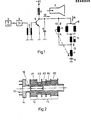
- the line deflection generator 2 is synchronized to the line frequency by the received television signal.
- the generator 2 controls the line output stage transistor 5 with a line-frequency switching voltage via the driver stage 3 and the driver transformer 4 in such a way that a sawtooth, line-frequency current flows in the primary winding 6 of the line transformer.
- the line-frequency deflection current iA is thereby generated in the deflection coils 8.
- the return capacitor 9 is used to tune the entire circuit and to achieve the desired conditions in the line return.
- the line deflection coils 8 effect the line deflection of the electron beam in the picture tube 7.
- the differential coil with the two coils 12, 13 is provided, the coil 12 being in series and the coil 13 lying parallel to the deflection coils 8.
- the coils 12, 13 can be changed in opposite directions in the inductance such that when the setting is made, the deflection current iA changes to set the desired image width, the impedance formed by the components 8, 10, 11, 12, 13, the total current iG taken from the line output stage and so the other values such as tuning, ramp-down time, high voltage etc. remain unchanged.
- Fig. 2 shows the formation of the amplitude differential coil formed by the coils 12, 13.
- the two coils 12, 13 are accommodated on a common chamber bobbin 14 which has four connecting pins 15 for the four ends of these two coils. All turns of the coil 12 are in the first chamber K1.
- the turns of the coil 13 are divided into the following chambers K2, K3, K4, K5, the number of turns increasing towards the end of the coil body 14.
- the core 16 is adjustably mounted by means of a thread and has a length approximately equal to the width of two to three chambers.
- the inductance of the two coils 12, 13 can be changed in opposite directions, but are not coupled to one another by means of transformers. Since the two coils 12, 13 are arranged on the same coil body with a common core, a Ver is not necessary in this case coupling of the two coils 12, 13 cannot be avoided. Because of this existing transformer coupling, the polarity of the two coils 12, 13 cannot be chosen arbitrarily. The coils 12, 13 are therefore polarized such that the same polarity of the voltage is present at the beginning or at the end of both coils. For example, at the end of coil 12 there is the positive return pulse and at the end of coil 13 there is also the positive return pulse from the beginning. The coils 12, 13 are thus polarized in the same direction with regard to the direction of the current flowing through. In Fig. 1 this is indicated by the symbols A (beginning) and E (end).
Landscapes
- Engineering & Computer Science (AREA)
- Power Engineering (AREA)
- Multimedia (AREA)
- Signal Processing (AREA)
- Details Of Television Scanning (AREA)
- Coils Or Transformers For Communication (AREA)
- Video Image Reproduction Devices For Color Tv Systems (AREA)
Applications Claiming Priority (2)
| Application Number | Priority Date | Filing Date | Title |
|---|---|---|---|
| DE19863618953 DE3618953A1 (de) | 1986-06-05 | 1986-06-05 | Amplitudenspule fuer die zeilenendstufe eines fernsehempfaengers |
| DE3618953 | 1986-06-05 |
Publications (2)
| Publication Number | Publication Date |
|---|---|
| EP0248329A2 true EP0248329A2 (fr) | 1987-12-09 |
| EP0248329A3 EP0248329A3 (fr) | 1990-03-07 |
Family
ID=6302351
Family Applications (1)
| Application Number | Title | Priority Date | Filing Date |
|---|---|---|---|
| EP87107643A Withdrawn EP0248329A3 (fr) | 1986-06-05 | 1987-05-26 | Bobine d'amplitude pour l'étage final de déviation ligne d'un récepteur de télévision |
Country Status (5)
| Country | Link |
|---|---|
| EP (1) | EP0248329A3 (fr) |
| JP (1) | JPS63260275A (fr) |
| KR (1) | KR910006687B1 (fr) |
| CN (1) | CN1014660B (fr) |
| DE (1) | DE3618953A1 (fr) |
Family Cites Families (14)
| Publication number | Priority date | Publication date | Assignee | Title |
|---|---|---|---|---|
| DE757101C (de) * | 1938-10-06 | 1954-02-08 | Telefunken Gmbh | Anordnung zur Erzielung einer frequenzlinearen Abstimmungskurve bei einem Empfaenger |
| NL99230B (fr) * | 1940-10-16 | |||
| US2389986A (en) * | 1943-06-11 | 1945-11-27 | Rca Corp | Permeability tuning system |
| NL159217B (nl) * | 1951-02-12 | Commissariat Energie Atomique | Werkwijze voor het bereiden van een neutronen absorberend materiaal. | |
| DE934176C (de) * | 1954-03-21 | 1955-10-13 | Walter Dr-Ing Reinecken | Verfahren zum kontinuierlichen Waermebehandeln von Draehten, Baendern, Rohren od. dgl. |
| US3119084A (en) * | 1958-08-04 | 1964-01-21 | Nytronics Inc | Electrical winding construction |
| US3138772A (en) * | 1959-05-28 | 1964-06-23 | Automatic Timing And Controls | Symmetrical differential transformers |
| US3329861A (en) * | 1964-08-31 | 1967-07-04 | Rca Corp | Dynamic raster distortion correction circuit having four window magnetic circuit |
| DE1246021B (de) * | 1966-03-17 | 1967-08-03 | Telefunken Patent | Ablenkschaltung, insbesondere fuer Farbfernsehgeraete |
| US3428929A (en) * | 1967-05-12 | 1969-02-18 | Amerline Corp | Coil receiving structure |
| JPS4885029A (fr) * | 1972-02-15 | 1973-11-12 | ||
| DE3005826C2 (de) * | 1980-02-16 | 1981-12-17 | Licentia Patent-Verwaltungs-Gmbh, 6000 Frankfurt | Schaltung zur Gewinnung eines Zeilenrücklaufimpulses in einem Fernsehempfänger |
| US4334173A (en) * | 1980-09-22 | 1982-06-08 | Zenith Radio Corporation | Horizontal width control circuit for image display apparatus |
| DD213567B1 (de) * | 1982-12-30 | 1991-01-17 | Engels Fernsehgeraete Veb | Schaltungsanordnung zur bildbreiteneinstellung und ost-west-rasterverschiebung |
-
1986
- 1986-06-05 DE DE19863618953 patent/DE3618953A1/de not_active Withdrawn
-
1987
- 1987-05-26 EP EP87107643A patent/EP0248329A3/fr not_active Withdrawn
- 1987-05-29 JP JP62131970A patent/JPS63260275A/ja active Pending
- 1987-06-04 CN CN87104021A patent/CN1014660B/zh not_active Expired
- 1987-06-05 KR KR1019870005699A patent/KR910006687B1/ko not_active Expired
Also Published As
| Publication number | Publication date |
|---|---|
| DE3618953A1 (de) | 1987-12-10 |
| JPS63260275A (ja) | 1988-10-27 |
| KR910006687B1 (ko) | 1991-08-30 |
| EP0248329A3 (fr) | 1990-03-07 |
| KR880001144A (ko) | 1988-03-31 |
| CN1014660B (zh) | 1991-11-06 |
| CN87104021A (zh) | 1987-12-16 |
Similar Documents
| Publication | Publication Date | Title |
|---|---|---|
| DE3217682C2 (de) | Ablenkschaltung mit asymmetrischer Linearitätskorrektur | |
| DE2504355C3 (de) | Elektronenstrahlröhren-Hochspannungsgenerator für Fernsehgeräte | |
| EP0248329A2 (fr) | Bobine d'amplitude pour l'étage final de déviation ligne d'un récepteur de télévision | |
| DE910673C (de) | Anordnung zur Zufuehrung von Betriebsspannungen an Schaltungsteile, die gegenueber ihrer Umgebung hohe Wechselspannungen fuehren | |
| DE2321149B2 (de) | Dyna mische Vertikal-Konvergenzschaltung | |
| WO1992010906A1 (fr) | Transformateur h.t. pour postes recepteurs de television | |
| DE3927883A1 (de) | Horizontalausgangsschaltung | |
| DE1925872C3 (de) | Dynamische Vertikalkonvergenzschaltung | |
| DE3783063T2 (de) | Selbstkonvergierende ablenkspule fuer eine in-line-farbbildroehre. | |
| DE1237699B (de) | Schaltungsanordnung zur Erzeugung einer einstellbaren Gleichspannung fuer eine Kathodenstrahlroehre | |
| DE2603949B2 (de) | Schaltungsanordnung in einem Fernsehempfänger zum Erzeugen eines horizontalfrequenten Ablenkstromes N.V. Philips' Gloeilampenfabrie- | |
| DE578849C (de) | Statischer Spannungsregler fuer Wechselstrom | |
| EP0171690A1 (fr) | Configuration de bobines avec noyau à cheville magnétisable | |
| EP0044909B1 (fr) | Dispositif répartiteur multiple pour signaux à hautes fréquences | |
| DE2200452B2 (de) | Schaltungsanordnung zur konvergenzkorrektur in einem fernsehempfaenger | |
| DE1281483C2 (de) | Schaltungsanordnung zur entzerrung des auf den leuchtschirm der kathodenstrahlroehre geschriebenen rasters | |
| DE1955104A1 (de) | Schaltungsanordnung mit Schaltungsmitteln zum periodischen Unterbrechen eines einer Induktivitaet zugefuehrten Stromes | |
| DE1766076B2 (de) | Mehrstufiger gegengekoppelter breitband transistorver staerker | |
| DE4224541C1 (de) | Linearitätskompensationsverfahren und Linearitätskompensationsgerät | |
| DE2808417A1 (de) | Selbstschwingende mischstufe mit einem gegentaktmischer | |
| DE2610843A1 (de) | Schaltungsanordnung zum erzeugen eines korrekturstromes zum korrigieren von ablenkfehlern am wiedergabeschirm einer farbbildwiedergaberoehre | |
| DE1941466B2 (de) | Vorrichtung mit saettigungsfaehiger spule zum ausgleich von verzerrungen insbesondere der kissenverzerrung bei farbfern sehroehren | |
| DE2403331C3 (de) | Schaltungsanordnung zum Erzeugen eines mittels einer Modulationsspannung beeinflußten sägezahniörmlgen Ablenkstromes durch eine Horlzontalablenk-Spule | |
| DE2341646C3 (de) | Schaltungsanordnung für eine Ablenkeinheit einer Farbfemsehbildwiedergaberöhre | |
| DE681701C (de) | UEber einen Frequenzbereich abstimmbares elektrisches Koppelsystem |
Legal Events
| Date | Code | Title | Description |
|---|---|---|---|
| PUAI | Public reference made under article 153(3) epc to a published international application that has entered the european phase |
Free format text: ORIGINAL CODE: 0009012 |
|
| AK | Designated contracting states |
Kind code of ref document: A2 Designated state(s): AT BE CH DE ES FR GB GR IT LI LU NL SE |
|
| PUAL | Search report despatched |
Free format text: ORIGINAL CODE: 0009013 |
|
| AK | Designated contracting states |
Kind code of ref document: A3 Designated state(s): AT BE CH DE ES FR GB GR IT LI LU NL SE |
|
| 17P | Request for examination filed |
Effective date: 19900810 |
|
| 17Q | First examination report despatched |
Effective date: 19920429 |
|
| STAA | Information on the status of an ep patent application or granted ep patent |
Free format text: STATUS: THE APPLICATION IS DEEMED TO BE WITHDRAWN |
|
| 18D | Application deemed to be withdrawn |
Effective date: 19920910 |
|
| RIN1 | Information on inventor provided before grant (corrected) |
Inventor name: POLLAK, ALFRED |