EP0246995A2 - Bande de roulement de pneumatiques - Google Patents
Bande de roulement de pneumatiques Download PDFInfo
- Publication number
- EP0246995A2 EP0246995A2 EP87630084A EP87630084A EP0246995A2 EP 0246995 A2 EP0246995 A2 EP 0246995A2 EP 87630084 A EP87630084 A EP 87630084A EP 87630084 A EP87630084 A EP 87630084A EP 0246995 A2 EP0246995 A2 EP 0246995A2
- Authority
- EP
- European Patent Office
- Prior art keywords
- ground
- tire
- convex
- tread
- engaging surface
- Prior art date
- Legal status (The legal status is an assumption and is not a legal conclusion. Google has not performed a legal analysis and makes no representation as to the accuracy of the status listed.)
- Granted
Links
Images


Classifications
-
- B—PERFORMING OPERATIONS; TRANSPORTING
- B60—VEHICLES IN GENERAL
- B60C—VEHICLE TYRES; TYRE INFLATION; TYRE CHANGING; CONNECTING VALVES TO INFLATABLE ELASTIC BODIES IN GENERAL; DEVICES OR ARRANGEMENTS RELATED TO TYRES
- B60C11/00—Tyre tread bands; Tread patterns; Anti-skid inserts
- B60C11/03—Tread patterns
- B60C11/13—Tread patterns characterised by the groove cross-section, e.g. for buttressing or preventing stone-trapping
- B60C11/1376—Three dimensional block surfaces departing from the enveloping tread contour
- B60C11/1384—Three dimensional block surfaces departing from the enveloping tread contour with chamfered block corners
-
- B—PERFORMING OPERATIONS; TRANSPORTING
- B60—VEHICLES IN GENERAL
- B60C—VEHICLE TYRES; TYRE INFLATION; TYRE CHANGING; CONNECTING VALVES TO INFLATABLE ELASTIC BODIES IN GENERAL; DEVICES OR ARRANGEMENTS RELATED TO TYRES
- B60C11/00—Tyre tread bands; Tread patterns; Anti-skid inserts
- B60C11/03—Tread patterns
- B60C11/0302—Tread patterns directional pattern, i.e. with main rolling direction
-
- B—PERFORMING OPERATIONS; TRANSPORTING
- B60—VEHICLES IN GENERAL
- B60C—VEHICLE TYRES; TYRE INFLATION; TYRE CHANGING; CONNECTING VALVES TO INFLATABLE ELASTIC BODIES IN GENERAL; DEVICES OR ARRANGEMENTS RELATED TO TYRES
- B60C11/00—Tyre tread bands; Tread patterns; Anti-skid inserts
- B60C11/03—Tread patterns
- B60C11/11—Tread patterns in which the raised area of the pattern consists only of isolated elements, e.g. blocks
-
- B—PERFORMING OPERATIONS; TRANSPORTING
- B60—VEHICLES IN GENERAL
- B60C—VEHICLE TYRES; TYRE INFLATION; TYRE CHANGING; CONNECTING VALVES TO INFLATABLE ELASTIC BODIES IN GENERAL; DEVICES OR ARRANGEMENTS RELATED TO TYRES
- B60C11/00—Tyre tread bands; Tread patterns; Anti-skid inserts
- B60C11/03—Tread patterns
- B60C11/13—Tread patterns characterised by the groove cross-section, e.g. for buttressing or preventing stone-trapping
- B60C11/1376—Three dimensional block surfaces departing from the enveloping tread contour
- B60C11/1392—Three dimensional block surfaces departing from the enveloping tread contour with chamfered block edges
Definitions
- the present invention relates to a tire having a tread with a base portion and a plurality of traction elements extending radially outwardly from said base portion, said traction elements each having a ground-engaging surface which communicates with said base portion by means of a plurality of walls, a plurality of said ground-engaging surfaces having a form such that the locus of the points on any of these plurality of ground-engaging surfaces traveling laterally across them at any location along their circumferential lengths defines a line which is continuously convex and has its center of curvature disposed radially inwardly of said convex line.
- a tire is known for example from US-A-1 092 353 and US A 1 505 233.
- the present invention also relates to a tire having a tread having a base portion and a plurality of traction elements extending radially outwardly from said base portion, said traction elements each having a ground-engaging surface which communicates with said base portion by means of a plurality of walls, a plurality of said ground-engaging surfaces having a form such that the locus of the points on these ground-engaging surfaces traveling in a circumferential direction at any location across axial width of these ground-engaging surfaces defines a line which is continuously convex and has its center of curvature disposed radially inwardly of said convex line.
- a tire is known for example from US-A-1 505 233 and FR-A-2 312 385.
- the contact pressure between the tread of a tire and a roadway is not uniform across the footprint of a tire in a lateral direction, nor is the contact pressure uniform for a given point on a ground-contacting surface of a tire tread as that point passes through the footprint of a rotating tire.
- the non-uniformity of contact pressure sometimes referred to in the tire art as unit tread pressure, affects the shape of the footprint and the operating characteristics of a tire.
- the present invention provides a means of attaining desirable operating characteristics for a tire by contouring the ground-engaging surfaces of the tire in a particular manner.
- the tread of a tire may have any number of traction elements which have ground-engaging surfaces.
- the ground-engaging surfaces of the traction elements of most tires conform substantially to the overall lateral and circumferential curvature of the tire.
- US-A-1 092 353 and US-A-1 505 233 that the ground-engaging surfaces of traction elements may follow a curved path which is convex as viewed in a radial cross-section of a tire, with the tread having an overall curvature that is not coincident with the ground-engaging surfaces of the traction elements.
- the tire 10 is a pneumatic tire having at least one carcass reinforcing ply 12,14 which extends between the bead portions 16,18 of the tire.
- Each of the bead portions contains a substantially inextensible annular bead core 20,22 around which each carcass ply is anchored.
- the carcass ply structure may be of the well known bias ply construction, although the well known radial ply construction is preferred.
- a tread-reinforcing member comprising at least one belt ply 24,26 is disposed radially outwardly of the carcass ply structure and radially inwardly of the tread portion 28 of the tire.
- radial and radially refer to directions perpendicular to the axis of rotation of a tire
- axial and axially refer to directions parallel to the axis of rotation of a tire.
- the tread portion 28 of the tire comprises an elastomeric substance such as natural or synthetic rubber, or a combination thereof.
- Sidewalls 30,32 extend generally radially inwardly from the tread portion to the bead portions 16,18.
- the tread portion as seen also in plan view in Fig. 2, comprises a plurality of traction elements 34 disposed on each side of a mid-circumferential centerplane CP.
- a "mid-circumferential centerplane" is a plane which is perpendicular to the axis of rotation of a tire, located midway between the lateral edges of the tread in a footprint of a tire that has been mounted on its specified rim, then inflated to its specified inflation pressure and subjected to its rated load.
- axially inwardly is understood to mean an axial direction going from a lateral edge of the tread towards the mid-circumferential centerplane
- axially outwardly is understood to mean an axial direction going from the mid-circumferential centerplane towards a lateral edge of the tread.
- radially inwardly is understood to mean a radial direction going towards the axis of rotation of a tire
- radially outwardly is understood to mean a radial direction going away from the axis of rotation of a tire.
- Fig. 3 is an enlargement of a portion of Fig. 1, as contained in the circle 3 of Fig. 1.
- the ground-engaging surfaces 36 of the prior art traction elements 34 have a concave profile (which is greatly exaggerated in this illustration). While the concavity of the traction elements, which can occur in both radial ply and bias ply tires, may be very inconspicuous to a casual observer of a tire, this condition can in fact have an adverse effect upon the operating characteristics of the tire, in a manner that will soon be explained herein.
- This concave condition can be caused at least in part by shrinkage of the elastomeric substance comprising the traction elements after the tire is removed from the mold in which it is vulcanized. It is understood that while the traction elements enlarged in Fig. 3 are located near the mid-circumferential centerplane CP of the tire, this concave condition can occur in any, or all, of the traction elements of a tread regardless of their location. Furthermore, it is understood that this concavity phenomena can occur regardless of the general geometric shape of the traction elements.
- Fig. 4 is a graph illustrating the contact pressure across the ground-engaging surface of a single traction element of a tire manufactured according to the prior art and a tire according to the present invention.
- the traction element was a continuous rib located at the mid-circumferential centerplane of a tire.
- a traction element is understood to mean both an individual button that is completely surrounded by a groove, or grooves, or a combination of grooves and a lateral edge of the tread, and a rib which extends circumferentially around a tire.
- a sensor which measures the radial force between a tire and a supporting surface was placed at various locations across the axial width of the corresponding traction element of both the prior art and the new tire.
- the tires were substantially identical in construction and tread design, with the exception of the contour of the ground engaging surfaces of the traction elements. These tires were mounted on the same size rims, and both were inflated to 100 kPa and subjected to a load of 363 kg.
- Solid line A on the graph represents the contact pressure across the width of the prior art traction element. It is clear that the contact pressure is lower at the center of the traction element than at the axial edges of the element. This same phenomena can be illustrated by referring to Fig. 5.
- Fig. 5 is the footprint of a prior art tire of size 280/50 - 13, mounted on its specified rim which is 28 cm wide, inflated to its specified inflation pressure of 124 kPa, and subjected to its specified load of 272 kg.
- the edges of the traction elements are generally in solid contact with the supporting surface while the central portions of the ground-engaging surfaces of the traction elements are not flat against the supporting surfaces.
- the effect of the concavity of the ground-engaging surfaces of prior art traction elements is lower contact pressure at the center of traction elements, which reduces the water evacuating efficiency of the tires when they are operated on water covered surfaces.
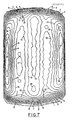
- Fig. 7 is an illustration of the complex pressure distributions that are experienced by a pneumatic tire. These pressure distributions are affected by many factors such as load, inflation pressure, cornering, speed and water on the roadway. Fig. 7 shows the distribution of contact pressure in the ground contact patch of a radial tire. The lines indicated by numerals are isobars of force in Newtons.
- Fig. 8 is a three-dimensional representation of the footprint and contact pressures of Fig. 7. While Figs. 7 and 8 are intended to be merely a representative example of a pressure distribution in a tire footprint, they do illustrate the complex nature of such a pressure distribution.
- This pressure distribution data was generated by mounting a tire on a rim having the design rim width for said tire, subjecting the tire to a load while the tire is inflated to its specified inflation pressure for said load, and repeatedly rolling the tire over a pin (7.62 mm x 7.62 mm square) and recording the force on the pin.
- a procedure has been described, for example, in TESTING AND ANALYSIS OF TIRE HYDROPLANING , by Robert W. Yeager and Jack L. Tuttle, published in 1972 by the Society of Automotive Engineers, Inc. as technical paper number 720471.
- Fig. 9 is an enlarged radial cross-sectional view of a portion of the crown region of a tire according to the present invention.
- the tread 50 of a tire according to the invention has a base portion 51 with a plurality of traction elements 52 extending radially outwardly from the base portion of the tread.
- the tread comprises an elastomeric material, or materials, having a modulus of elasticity in the range of 20 to 20 Meganewtons per meter2 at 300% elongation per ASTM Standard D412.
- Each traction element 52 has a ground-engaging surface 53 which communicates with the base portion of the tread by means of a plurality of walls 54 which are preferably disposed substantially perpendicular to the axis of rotation of the tire.
- substantially perpendicular means within 15° of being exactly perpendicular.
- the walls may also serve as the walls of grooves which serve as paths for the evacuation of water from the footprint of the tire.
- the traction elements 52 are preferably disposed such that every possible radial cross-section of the tire intersects a plurality of traction elements which have ground-engaging surfaces 53 which are convex. That is to say, a plurality of said ground-engaging surfaces have a form such that the locus of the points on these ground-engaging surfaces of the traction elements traveling laterally across them at any location along their circumferential length follows a path and defines a line which is continuously convex and has its center of curvature disposed radially inwardly of the convex line.
- locus is understood to mean the set of all points whose location is determined by stated conditions.
- the locus of the points on the ground-engaging surfaces can be determined using a dial-indicator or other suitable gauge at various locations laterally across the ground-engaging surface.
- lateral and “laterally” refer to directions perpendicular to the mid-circumferential centerplane of a tire.
- the tread has a tread arc of a radius such that the tread arc is not coincident with the ground-engaging surfaces of the traction elements.
- the design rim width for a tire and its specified inflation pressure for a given load are those recommended by the manufacture of a tire, or if not available from the manufacturer, those specified by an organization setting industrial standards for tires and rims in the locality where the tire was manufactured. Examples of such organizations are The Tire & Rim Association, Inc. in the United States of America, and The European Tyre and Rim Technical Organization in Europe.
- a "tread arc" is the overall curvature of the tread in a lateral direction. It is possible to practice the present invention without modifying the ground-engaging surface of every traction element of a tire tread. The particular arrangement and geometric shape of the traction elements may be selected by a tire engineer in accordance with the use intended for that tire.
- a tire according to the invention have a radial ply carcass with a tread-reinforcing member, commonly referred to in the art as a belt structure 55,56, interposed between the radial ply carcass and the base portion of the tread.
- the belt structure is an important component of any tire (either bias ply or radial ply) according to the invention because one of the purposes of any belt ply is to hold the tread firmul against the road.
- the intermittent dashed line B represents the contact pressure across the axial width of the ground-engaging surface of a traction element wherein said ground-engaging surface follows, in a transverse direction, a path which is continuously convex.
- the contact pressure is higher at the center of the ground-engaging surface than at its edges. This means that the convex ground-engaging surfaces of a tire according to the invention should not trap water between their edges.
- Fig. 6 there is shown a footprint of a tire according to the invention.
- the new tire is of the same size, and mounted on the same size rim, inflated to the same pressure, and subjected to the same load as the prior art tire whose footprint is shown in Fig. 5. That is to say, the new tire was also mounted on a rim having the design rim width for said tire, and subjected to a load while inflated to the specified inflation pressure for said load.
- the tread pattern for the new tire in this example is slightly different that that of the prior art tire of Fig. 5, but in other respects the structures of the tires was substantially the same.
- In the footpring of the new tire there is good contact between the ground-engaging surfaces of the tire and the supporting surface at the center of the ground-engaging surfaces, and areas of lesser contact at the edges of some of the ground-engaging surfaces.
- This footprint reinforces the theory that water will not be trapped between the edges of a ground-engaging surface of a traction element according to the invention and thereby attains better contact of the tire with the ground.
- the variation between the convex paths or lines defined by the locus of the points on the ground-engaging surfaces of traction elements across the width of the tread is needed because the unit tread pressure varies across the width of the tread, as illustrated in Figs. 7 and 8.
- the amplitude of the convex path or line defined by the ground-engaging surface of each traction element varies between traction elements across the axial width of the tread with respect to the variation in unit tread pressure across the axial width of a footprint of the tire when the tire is mounted on a rim having the design rim width for said tire, and subjected to a load while inflated to the specified inflation pressure for said load such that the amplitude of the convex line is greater for a ground-engaging surface located in a region of relatively high unit pressure and lesser for a ground-engaging surface located in a region of relatively low unit pressure.
- a tire according to the invention will still have variations in unit tread pressure at various locations in its ground-contact patch and the amplitude of the crowned ground-engaging surfaces will vary in a direct relationship to the variation in unit tread pressure across the axial width of the tread portion of the tire.
- the amplitude a of the convex path is the greatest distance of any point on the ground-engaging surface 53 from a baseline b extending between the radially outer edges of the axially opposing walls 34 of the traction element whose ground-engaging surface is being measured. It is not necessary that the convex line defined by the locus of the points be an arc of a circle, or even that the greatest amplitude of the convex line be at the axial center of the ground-engaging surface.
- Fig. 10 a diagrammatic representation of a radial cross-sectional view of the crown region of a size 455/50 - 13 tire that was manufactured according to the invention.
- the axial width of the ground-engaging surface of each of the traction elements 1-9 was 2.54 cm and the greatest amplitude y for each of the traction elements was:
- the variation in amplitude of the convex lines defined by the ground-engaging surfaces need not be very large, in fact, the range is only on the order of .06 mm.
- the radial height h of the walls connecting the ground-engaging surfaces to the base portion of the tread is about 6.4 mm so that the convex path has a maximum amplitude of about .1% of the radial height h that a prior art traction element would have.
- the centermost traction element 5 has the greatest degree of convexity and the convexity decreases as a function of each traction element's distance from the mid-circumferential plane CP of the tire.
- the tire of this example has its greatest unit tread pressure in the center of the tire, so that the amplitude of the ground-engaging surfaces of the traction elements decreases as the unit tread pressure decreases.
- the amplitude of the convex lines defined by the ground-engaging surfaces of the traction elements should increase as the distance of the traction elements from the mid-circumferential plane of the tire increases.
- the amplitude of the convex lines defined by the ground-engaging surfaces should be optimized by the tire designer and is dependent upon the carcass ply and belt structure of the tire as well as the geometric shape of the traction elements and the material which comprises the tread of the tire.
- Figs. 7 and 8 which show the unit tread pressure distribution in the footprint of a radial tire, it is evident that the contact pressure on any given point on a ground-engaging surface of the tread will vary as that point passes through a footprint of the tire.
- Fig. 11 shows a partial cross-section of a tire 60 taken perpendicular to the axis of rotation of the tire, wherein the cross-section intersects the ground-engaging surface 61 of at least one traction element, said ground-engaging surfaces communicating with a base portion 62 of the tread by means of a plurality of walls 63 which are preferably disposed substantially perpendicular to the axis of rotation of the tire.
- the locus of the points on said ground-engaging surfaces of the traction elements traveling in a circumferential direction at any location across the axial width to the ground-engaging surface follows a path and defines a line which is continuously convex, said line not being coincident with any circle that has its center located on the axis of rotation of the tire.
- the greatest amplitude of the convex line is located at a point other than the mid-point MP of the circumferential length of the traction element.
- the greatest amplitude of the convex line defined by the ground-engaging surface of a traction element in a circumferential direction is located either: (a) between the mid-point of the circumferential length of a traction element and a leading edge of the ground-engaging surface; or (b) between the mid-point and a trailing edge of the ground-engaging surface.
- the amplitude of the convex line defined by the locus of the points on the ground-engaging surface of at least one of the traction elements intersected by said cross-section is different from the amplitude of the convex line defined by the locus of the points followed by the ground-engaging surface of at least one of the other traction elements intersected by the cross-section, traveling in a circumferential direction.
- the location of the greatest amplitude of the convex lines may also vary between ground-engaging surfaces.
- a "leading edge" of a traction element is the first edge of the ground-engaging surface to enter the footprint of a rotating tire and the “trailing edge” is the last edge of the ground-engaging surface to enter the footprint of a rotating tire.
- the "mid-point of the circumferential length" of a traction element is located midway between the leading and trailing edges of a traction element on a plane that includes the axis of rotation of the tire.
- a tire according to this aspect of the invention will have a more uniform unit tread pressure especially if the tire is a directional type of tire.
- a directional tire has a tread pattern that is designed to operate differently when the tire is rotated in opposite directions.
- every traction element is continuously convex in both the lateral and circumferential directions, as disclosed herein, it is possible to have a tire with traction elements with ground-engaging surfaces that are convex only in an axial direction, or only in a circumferential direction, or a mixture of traction elements of the three types on a single tire.
Landscapes
- Engineering & Computer Science (AREA)
- Mechanical Engineering (AREA)
- Tires In General (AREA)
Applications Claiming Priority (2)
| Application Number | Priority Date | Filing Date | Title |
|---|---|---|---|
| US06/864,396 US4722378A (en) | 1986-05-19 | 1986-05-19 | Tire treads with convex elements |
| US864396 | 1986-05-19 |
Publications (3)
| Publication Number | Publication Date |
|---|---|
| EP0246995A2 true EP0246995A2 (fr) | 1987-11-25 |
| EP0246995A3 EP0246995A3 (en) | 1989-07-26 |
| EP0246995B1 EP0246995B1 (fr) | 1993-01-27 |
Family
ID=25343179
Family Applications (1)
| Application Number | Title | Priority Date | Filing Date |
|---|---|---|---|
| EP87630084A Expired - Lifetime EP0246995B1 (fr) | 1986-05-19 | 1987-05-14 | Bande de roulement de pneumatiques |
Country Status (5)
| Country | Link |
|---|---|
| US (1) | US4722378A (fr) |
| EP (1) | EP0246995B1 (fr) |
| JP (2) | JPS62279105A (fr) |
| CA (1) | CA1270734A (fr) |
| DE (1) | DE3783802T2 (fr) |
Cited By (6)
| Publication number | Priority date | Publication date | Assignee | Title |
|---|---|---|---|---|
| WO1997021555A1 (fr) * | 1995-12-11 | 1997-06-19 | The Goodyear Tire & Rubber Company | Bande de roulement pour pneu |
| EP0787600A1 (fr) * | 1996-02-05 | 1997-08-06 | The Goodyear Tire & Rubber Company | Bandage pneumatique ayant de bonnes propriétés diverses |
| EP0875403A2 (fr) * | 1997-05-02 | 1998-11-04 | Bridgestone Corporation | Bandage pneumatique |
| WO2000050252A1 (fr) * | 1999-02-22 | 2000-08-31 | Bridgestone Corporation | Pneumatique |
| EP1541382A1 (fr) * | 2002-09-10 | 2005-06-15 | The Yokohama Rubber Co., Ltd. | Pneumatique |
| CN103879236A (zh) * | 2012-12-19 | 2014-06-25 | 住友橡胶工业株式会社 | 充气轮胎 |
Families Citing this family (42)
| Publication number | Priority date | Publication date | Assignee | Title |
|---|---|---|---|---|
| JPS63162308A (ja) * | 1986-12-26 | 1988-07-05 | Bridgestone Corp | 高速走行に供せられる偏平空気入りラジアルタイヤ |
| US5174214A (en) * | 1989-02-22 | 1992-12-29 | Bridgestone Corporation | Radial tire for levitation-type vehicle |
| US4953604A (en) * | 1989-05-25 | 1990-09-04 | The Goodyear Tire & Rubber Company | Tread for a unidirectional pneumatic tire |
| US4984616A (en) * | 1989-05-25 | 1991-01-15 | The Goodyear Tire & Rubber Company | Front and rear tire tread patterns in a four-wheeled tire/vehicle system |
| US5002109A (en) * | 1989-05-25 | 1991-03-26 | The Goodyear Tire & Rubber Company | Symmetrical and directional pneumatic tire tread |
| JP2892042B2 (ja) * | 1989-06-06 | 1999-05-17 | 住友ゴム工業 株式会社 | 低騒音タイヤ |
| DE9002986U1 (fr) * | 1990-03-12 | 1991-04-04 | Uniroyal Englebert Reifen Gmbh, 5100 Aachen, De | |
| JP2667280B2 (ja) * | 1990-05-07 | 1997-10-27 | ナショナルタイヤ株式会社 | 自転車用タイヤ |
| US5353854A (en) * | 1991-03-08 | 1994-10-11 | The Goodyear Tire & Rubber Company | Pneumatic tire having laterally connected lugs |
| EP0512825B1 (fr) * | 1991-05-09 | 1995-12-06 | Bridgestone Corporation | Bandages pneumatiques |
| ES2133493T3 (es) * | 1993-10-12 | 1999-09-16 | Bridgestone Corp | Molde para vulcanizar una cubierta neumatica. |
| JP3533246B2 (ja) * | 1993-11-05 | 2004-05-31 | 株式会社ブリヂストン | 空気入りタイヤ |
| JP2799137B2 (ja) * | 1993-12-29 | 1998-09-17 | 住友ゴム工業株式会社 | 空気入りタイヤ |
| JP3515296B2 (ja) * | 1996-10-28 | 2004-04-05 | 横浜ゴム株式会社 | 重荷重用空気入りタイヤ |
| JP3384716B2 (ja) * | 1997-09-02 | 2003-03-10 | 住友ゴム工業株式会社 | 空気入りタイヤ |
| EP0916524A3 (fr) * | 1997-11-12 | 2000-11-08 | Bridgestone Corporation | Bandages pneumatiques radiaux |
| DE19937067A1 (de) * | 1999-08-05 | 2001-02-08 | Dunlop Gmbh | Fahrzeugreifen mit einer profilierten Lauffläche |
| US6564839B1 (en) | 2000-11-01 | 2003-05-20 | The Goodyear Tire & Rubber Company | Pneumatic tire having a load dependent adaptive footprint shape |
| US6860053B2 (en) * | 2002-06-01 | 2005-03-01 | Ned F. Christiansen | Grip friction pattern |
| JP4316324B2 (ja) * | 2003-08-08 | 2009-08-19 | 横浜ゴム株式会社 | 空気入りタイヤ |
| JP4626269B2 (ja) * | 2004-10-29 | 2011-02-02 | 横浜ゴム株式会社 | 空気入りタイヤ |
| JP4626333B2 (ja) * | 2005-02-21 | 2011-02-09 | 横浜ゴム株式会社 | 空気入りタイヤ |
| DE102007059290A1 (de) | 2007-12-08 | 2009-06-10 | Continental Aktiengesellschaft | Fahrzeugluftreifen |
| CN101555620A (zh) * | 2008-04-07 | 2009-10-14 | Axt公司 | 晶体生长装置及方法 |
| US8261790B2 (en) * | 2008-08-18 | 2012-09-11 | The Goodyear Tire & Rubber Company | Directional tread for a tire |
| JP4973708B2 (ja) * | 2009-09-11 | 2012-07-11 | 横浜ゴム株式会社 | 空気入りタイヤ |
| US20110079334A1 (en) * | 2009-10-02 | 2011-04-07 | Andreas Bott | Tire tread having improved contact pressure distribution |
| JP4826681B1 (ja) * | 2010-11-17 | 2011-11-30 | 横浜ゴム株式会社 | 空気入りタイヤ |
| JP5387707B2 (ja) * | 2012-03-14 | 2014-01-15 | 横浜ゴム株式会社 | 空気入りタイヤ |
| WO2014038689A1 (fr) * | 2012-09-07 | 2014-03-13 | コンパニー ゼネラール デ エタブリッスマン ミシュラン | Bande de roulement pour pneumatique et pneumatique mettant en oeuvre cette bande de roulement |
| JP5790876B2 (ja) * | 2013-02-25 | 2015-10-07 | 横浜ゴム株式会社 | 空気入りタイヤ |
| CN105142932B (zh) * | 2013-03-18 | 2017-05-31 | 株式会社普利司通 | 轮胎 |
| JP6253941B2 (ja) * | 2013-10-09 | 2017-12-27 | 株式会社ブリヂストン | タイヤ |
| CN105705345B (zh) * | 2013-11-06 | 2018-05-15 | 横滨橡胶株式会社 | 充气轮胎 |
| JP6292067B2 (ja) * | 2014-07-25 | 2018-03-14 | 横浜ゴム株式会社 | 空気入りタイヤ |
| JP6526402B2 (ja) * | 2014-10-27 | 2019-06-05 | 株式会社ブリヂストン | 空気入りタイヤ |
| US11628640B2 (en) * | 2016-05-31 | 2023-04-18 | Compagnie Generale Des Etablissements Michelin | Molding element for manufacturing a noise reducing tread |
| DE102016211505A1 (de) | 2016-06-27 | 2017-12-28 | Continental Reifen Deutschland Gmbh | Formsegment |
| CN107804119B (zh) * | 2016-09-09 | 2019-11-12 | 建大工业股份有限公司 | 轮胎 |
| US11034192B2 (en) * | 2016-10-03 | 2021-06-15 | Kenda Rubber Ind. Co., Ltd. | Tire |
| JP6819212B2 (ja) * | 2016-10-26 | 2021-01-27 | 住友ゴム工業株式会社 | 空気入りタイヤ |
| JP6819213B2 (ja) * | 2016-10-26 | 2021-01-27 | 住友ゴム工業株式会社 | 空気入りタイヤ |
Citations (3)
| Publication number | Priority date | Publication date | Assignee | Title |
|---|---|---|---|---|
| US3410329A (en) * | 1967-03-14 | 1968-11-12 | Gen Tire & Rubber Co | Asymmetrical dual tread pneumatic tires |
| DE2343747A1 (de) * | 1973-08-30 | 1975-03-06 | Continental Gummi Werke Ag | Fahrzeugluftreifen |
| FR2312385A1 (fr) * | 1975-05-30 | 1976-12-24 | Uniroyal | Structure de bande de roulement et enveloppe de bandage pneumatique en comportant application |
Family Cites Families (9)
| Publication number | Priority date | Publication date | Assignee | Title |
|---|---|---|---|---|
| US925937A (en) * | 1909-06-22 | Elastic vehicle-tire | ||
| US1057164A (en) * | 1912-03-19 | 1913-03-25 | John Henry Messenger | Tire. |
| US1092353A (en) * | 1912-08-15 | 1914-04-07 | Michael Hallanan | Tire. |
| US1505233A (en) * | 1922-10-12 | 1924-08-19 | Fisk Rubber Co | Rut guard |
| LU38258A1 (fr) * | 1957-06-04 | |||
| US3177917A (en) * | 1963-10-28 | 1965-04-13 | Gates Rubber Co | Traction tread portion for tire casing |
| US3805865A (en) * | 1969-10-15 | 1974-04-23 | W Price | Tire tread construction |
| FR2317112A1 (fr) * | 1975-07-07 | 1977-02-04 | Michelin & Cie | Perfectionnements aux enveloppes de pneumatiques |
| US4456046A (en) * | 1981-05-11 | 1984-06-26 | Miller Timothy I | High-speed tires |
-
1986
- 1986-05-19 US US06/864,396 patent/US4722378A/en not_active Expired - Lifetime
-
1987
- 1987-05-11 CA CA000536796A patent/CA1270734A/fr not_active Expired - Fee Related
- 1987-05-14 EP EP87630084A patent/EP0246995B1/fr not_active Expired - Lifetime
- 1987-05-14 DE DE87630084T patent/DE3783802T2/de not_active Expired - Fee Related
- 1987-05-18 JP JP62119139A patent/JPS62279105A/ja active Pending
-
1994
- 1994-12-27 JP JP1994015973U patent/JP2529829Y2/ja not_active Expired - Lifetime
Patent Citations (3)
| Publication number | Priority date | Publication date | Assignee | Title |
|---|---|---|---|---|
| US3410329A (en) * | 1967-03-14 | 1968-11-12 | Gen Tire & Rubber Co | Asymmetrical dual tread pneumatic tires |
| DE2343747A1 (de) * | 1973-08-30 | 1975-03-06 | Continental Gummi Werke Ag | Fahrzeugluftreifen |
| FR2312385A1 (fr) * | 1975-05-30 | 1976-12-24 | Uniroyal | Structure de bande de roulement et enveloppe de bandage pneumatique en comportant application |
Cited By (12)
| Publication number | Priority date | Publication date | Assignee | Title |
|---|---|---|---|---|
| WO1997021555A1 (fr) * | 1995-12-11 | 1997-06-19 | The Goodyear Tire & Rubber Company | Bande de roulement pour pneu |
| US5746849A (en) * | 1995-12-11 | 1998-05-05 | The Goodyear Tire & Rubber Company | Tire tread including tie bar |
| EP0787600A1 (fr) * | 1996-02-05 | 1997-08-06 | The Goodyear Tire & Rubber Company | Bandage pneumatique ayant de bonnes propriétés diverses |
| EP0875403A2 (fr) * | 1997-05-02 | 1998-11-04 | Bridgestone Corporation | Bandage pneumatique |
| EP0875403A3 (fr) * | 1997-05-02 | 1999-12-29 | Bridgestone Corporation | Bandage pneumatique |
| US6076579A (en) * | 1997-05-02 | 2000-06-20 | Bridgestone Corporation | Pneumatic tire including block shaped lands having chamfering |
| US6332485B1 (en) | 1997-05-02 | 2001-12-25 | Bridgestone Corporation | Pneumatic tire including rib-shaped lands |
| WO2000050252A1 (fr) * | 1999-02-22 | 2000-08-31 | Bridgestone Corporation | Pneumatique |
| US6910512B1 (en) | 1999-02-22 | 2005-06-28 | Bridgestone Corporation | Pneumatic tire having peripheral protuberant portion on each block |
| EP1541382A1 (fr) * | 2002-09-10 | 2005-06-15 | The Yokohama Rubber Co., Ltd. | Pneumatique |
| EP1541382A4 (fr) * | 2002-09-10 | 2007-05-02 | Yokohama Rubber Co Ltd | Pneumatique |
| CN103879236A (zh) * | 2012-12-19 | 2014-06-25 | 住友橡胶工业株式会社 | 充气轮胎 |
Also Published As
| Publication number | Publication date |
|---|---|
| DE3783802T2 (de) | 1994-01-20 |
| JPS62279105A (ja) | 1987-12-04 |
| DE3783802D1 (de) | 1993-03-11 |
| EP0246995A3 (en) | 1989-07-26 |
| JPH0743621U (ja) | 1995-09-05 |
| CA1270734A (fr) | 1990-06-26 |
| JP2529829Y2 (ja) | 1997-03-19 |
| US4722378A (en) | 1988-02-02 |
| EP0246995B1 (fr) | 1993-01-27 |
Similar Documents
| Publication | Publication Date | Title |
|---|---|---|
| EP0246995B1 (fr) | Bande de roulement de pneumatiques | |
| US3976115A (en) | Pneumatic tire | |
| US5415215A (en) | Asymmetric tire | |
| AU601089B2 (en) | Pneumatic tire | |
| US4462446A (en) | Pneumatic tire tread | |
| EP0369932B1 (fr) | Bandage pneumatique pour véhicules | |
| US5042546A (en) | Radial ply pneumatic tire with reverse curvature carcass ply | |
| AU631072B2 (en) | Tire tread | |
| US4702292A (en) | High performance all-season tire tread | |
| CA2159236A1 (fr) | Pneumatique et bande de roulement de pneumatique pour camion a essieu directeur | |
| GB2160829A (en) | Multi-siped tire for low noise running | |
| CA1334373C (fr) | Pneu radial pour vehicules lourds | |
| EP1676723A1 (fr) | Pneumatique avec rainures transversales à l'épaule | |
| US4567929A (en) | Bias ply pneumatic tire tread with lateral notches | |
| EP0816131B1 (fr) | Pneumatique poids lourds | |
| GB2253817A (en) | Ribbed tire tread having high density siping zones in the rib regions | |
| AU606767B2 (en) | Radial-ply pneumatic tire with reverse curvature carcass ply | |
| JP3254171B2 (ja) | 重荷重用空気入りタイヤ | |
| USRE30549E (en) | Pneumatic tire | |
| CA1143265A (fr) | Semelle de pneu a saillies independantes | |
| US4967822A (en) | Pneumatic tire for a vehicular tire and wheel assembly | |
| EP0434015B1 (fr) | Pneumatique radial pour voitures | |
| EP0434014B1 (fr) | Pneumatique radial pour voitures | |
| EP0858917A2 (fr) | Bandage pneumatique | |
| EP0351349B1 (fr) | Bande de roulement de pneumatiques |
Legal Events
| Date | Code | Title | Description |
|---|---|---|---|
| PUAI | Public reference made under article 153(3) epc to a published international application that has entered the european phase |
Free format text: ORIGINAL CODE: 0009012 |
|
| 17P | Request for examination filed |
Effective date: 19870527 |
|
| AK | Designated contracting states |
Kind code of ref document: A2 Designated state(s): DE FR GB IT |
|
| PUAL | Search report despatched |
Free format text: ORIGINAL CODE: 0009013 |
|
| AK | Designated contracting states |
Kind code of ref document: A3 Designated state(s): DE FR GB IT |
|
| 17Q | First examination report despatched |
Effective date: 19910528 |
|
| ITTA | It: last paid annual fee | ||
| GRAA | (expected) grant |
Free format text: ORIGINAL CODE: 0009210 |
|
| AK | Designated contracting states |
Kind code of ref document: B1 Designated state(s): DE FR GB IT |
|
| REF | Corresponds to: |
Ref document number: 3783802 Country of ref document: DE Date of ref document: 19930311 |
|
| ET | Fr: translation filed | ||
| ITF | It: translation for a ep patent filed |
Owner name: MODIANO & ASSOCIATI S.R.L. |
|
| PLBE | No opposition filed within time limit |
Free format text: ORIGINAL CODE: 0009261 |
|
| STAA | Information on the status of an ep patent application or granted ep patent |
Free format text: STATUS: NO OPPOSITION FILED WITHIN TIME LIMIT |
|
| 26N | No opposition filed | ||
| PGFP | Annual fee paid to national office [announced via postgrant information from national office to epo] |
Ref country code: FR Payment date: 20010503 Year of fee payment: 15 |
|
| REG | Reference to a national code |
Ref country code: GB Ref legal event code: IF02 |
|
| PG25 | Lapsed in a contracting state [announced via postgrant information from national office to epo] |
Ref country code: FR Free format text: LAPSE BECAUSE OF NON-PAYMENT OF DUE FEES Effective date: 20030131 |
|
| REG | Reference to a national code |
Ref country code: FR Ref legal event code: ST |
|
| PGFP | Annual fee paid to national office [announced via postgrant information from national office to epo] |
Ref country code: GB Payment date: 20030401 Year of fee payment: 17 |
|
| PGFP | Annual fee paid to national office [announced via postgrant information from national office to epo] |
Ref country code: DE Payment date: 20030530 Year of fee payment: 17 |
|
| PG25 | Lapsed in a contracting state [announced via postgrant information from national office to epo] |
Ref country code: GB Free format text: LAPSE BECAUSE OF NON-PAYMENT OF DUE FEES Effective date: 20040514 |
|
| PG25 | Lapsed in a contracting state [announced via postgrant information from national office to epo] |
Ref country code: DE Free format text: LAPSE BECAUSE OF NON-PAYMENT OF DUE FEES Effective date: 20041201 |
|
| GBPC | Gb: european patent ceased through non-payment of renewal fee |
Effective date: 20040514 |
|
| PG25 | Lapsed in a contracting state [announced via postgrant information from national office to epo] |
Ref country code: IT Free format text: LAPSE BECAUSE OF NON-PAYMENT OF DUE FEES;WARNING: LAPSES OF ITALIAN PATENTS WITH EFFECTIVE DATE BEFORE 2007 MAY HAVE OCCURRED AT ANY TIME BEFORE 2007. THE CORRECT EFFECTIVE DATE MAY BE DIFFERENT FROM THE ONE RECORDED. Effective date: 20050514 |