EP0244555A2 - Brique murale - Google Patents
Brique murale Download PDFInfo
- Publication number
- EP0244555A2 EP0244555A2 EP87100896A EP87100896A EP0244555A2 EP 0244555 A2 EP0244555 A2 EP 0244555A2 EP 87100896 A EP87100896 A EP 87100896A EP 87100896 A EP87100896 A EP 87100896A EP 0244555 A2 EP0244555 A2 EP 0244555A2
- Authority
- EP
- European Patent Office
- Prior art keywords
- brick
- side parts
- profile
- wall
- groove
- Prior art date
- Legal status (The legal status is an assumption and is not a legal conclusion. Google has not performed a legal analysis and makes no representation as to the accuracy of the status listed.)
- Granted
Links
Images

Classifications
-
- E—FIXED CONSTRUCTIONS
- E04—BUILDING
- E04C—STRUCTURAL ELEMENTS; BUILDING MATERIALS
- E04C1/00—Building elements of block or other shape for the construction of parts of buildings
- E04C1/39—Building elements of block or other shape for the construction of parts of buildings characterised by special adaptations, e.g. serving for locating conduits, for forming soffits, cornices, or shelves, for fixing wall-plates or door-frames, for claustra
-
- E—FIXED CONSTRUCTIONS
- E04—BUILDING
- E04B—GENERAL BUILDING CONSTRUCTIONS; WALLS, e.g. PARTITIONS; ROOFS; FLOORS; CEILINGS; INSULATION OR OTHER PROTECTION OF BUILDINGS
- E04B2/00—Walls, e.g. partitions, for buildings; Wall construction with regard to insulation; Connections specially adapted to walls
- E04B2/02—Walls, e.g. partitions, for buildings; Wall construction with regard to insulation; Connections specially adapted to walls built-up from layers of building elements
- E04B2/14—Walls having cavities in, but not between, the elements, i.e. each cavity being enclosed by at least four sides forming part of one single element
- E04B2/22—Walls having cavities in, but not between, the elements, i.e. each cavity being enclosed by at least four sides forming part of one single element using elements having a general shape differing from that of a parallelepiped
Definitions
- the invention relates to a brick with two opposing end walls that form the abutting surfaces for a respectively laterally adjacent brick, and to these walls that run perpendicularly and form the free wall surface.
- Such bricks are manufactured, for example, as sand-lime bricks, aerated concrete blocks, cement-bound building blocks and in particular as bricks.
- You are e.g. B. numerous known as so-called perforated brick and are used in practice on a large scale.
- these bricks generally have elongated holes in cross section, the longitudinal direction of the outer walls running in the direction of the masonry, that is to say transversely to the direction of heat transfer.
- the holes are usually offset from one another, as a result of which the webs between the holes, which are mainly responsible for heat transport, reach a maximum length. Due to this structure, however, it is no longer possible to process the perforated bricks by hand, especially when they are hit for example, need to be cut. Rather, the stones have to be sawn, which not only requires the provision of an additional tool, but is also time-consuming and cumbersome.
- the invention has for its object to provide a brick of the type mentioned, which can be easily adapted to the size required in each case, without the need for special tools or a correspondingly expensive storage.
- a brick that solves this problem is characterized by two brick elements, each with an essentially U-shaped cross-sectional shape, which face each other with profile legs that face one another and are designed as side parts, which together form the side walls and each in Groove pockets of the other brick element protrude, the groove pockets running parallel to the side parts adjoining them and extending in depth approximately to the profile back of the brick element forming the end wall.
- the progress achieved by the invention consists essentially in the fact that the two interlocking brick elements can be displaced to a large extent in the direction of the side parts and thus form a brick of variable length. If the entire possible displacement path is used, the length of the stone can be almost doubled compared to the brick elements that are completely pushed together. Due to the thickness of the end walls, an exact doubling of the stone length is not possible; however, this slight step change in dimensions can easily be compensated for by a joint mortar joint of the same thickness. This brick saves a considerable amount of working time when creating masonry, since any desired length dimension can be produced simply by pushing the two brick elements into each other without mechanical processing of the brick.
- a first embodiment of the invention is characterized in that on one brick element Side parts are connected at the end to the profile back forming the end wall and both groove pockets are arranged on the inside of the profile, and that the side parts with the groove pocket on the outside of the profile forming distance from the free end of the profile back forming the end wall are connected to the other brick element.
- This embodiment has the advantage that one brick element encompasses the other so that mutual lateral evasion is excluded.
- two brick elements with different shapes must be provided for this.
- both brick elements have the same shape in cross-section, the one side part being connected at the end with a groove pocket arranged on the inside of the profile and the other side part with the distance from the free end of the profile back forming the end wall forming the groove pocket on the outside of the profile.
- the cavity formed between the brick elements can be filled with loose filling bricks of any shape.
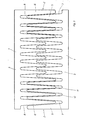
- one or more slats which protrude in the same direction as the side parts, are arranged on the end wall of the brick element between the side parts, the slats between them Form recordings for the slats of the other brick element.
- the subsequent filling of the cavity between the brick elements is eliminated, and on the other hand, very good thermal insulation properties can be achieved by a finely structured design of the slats.
- the slender slats also ensure little mortar penetration into the slat receptacles, even when the brick elements are pulled apart.
- the slats can have a rectangular cross section; in another advantageous embodiment, the side parts and / or the slats taper towards their free end. It is also advantageous if the slats are narrower than the side parts. As a result, despite the slender design of the slats in the area of its circumference, the brick has a greater material thickness which ensures the required load.
- the lamellae arranged in the central area of the brick element can have a shorter length, so that they form a mortar pocket in the center of the stone when the brick elements are pulled apart. This can also be advantageous if only one of these brick elements with the slats abuts a straight stone surface.
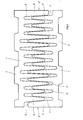
- the end wall can be provided on the outside with teeth that are trapezoidal in cross section, which engages approximately in a form-fitting manner in an abutting, appropriately shaped brick, the individual slats being of such a length that the imaginary boundary surface spanned by their free ends forms a corresponding trapezoidal toothing.
- teeth that are trapezoidal in cross section, which engages approximately in a form-fitting manner in an abutting, appropriately shaped brick, the individual slats being of such a length that the imaginary boundary surface spanned by their free ends forms a corresponding trapezoidal toothing.
- the slats and / or the side parts can be provided with cavities extending between the two bearing surfaces perpendicular to the front and side walls.
- the invention also relates to a method for producing a brick with the above-mentioned mer kmalen, in which the brick is shaped by the extrusion process and then cut to the desired length by a cutting wire.
- the object of the method is to prevent burrs from occurring on the cut surface, which would prevent the two brick elements from being pushed into one another.
- This object is achieved from a procedural point of view in that after cutting, the brick is brushed on its cut surfaces in the longitudinal direction of the slats in order to remove the cutting burr.
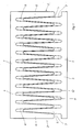
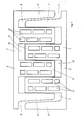
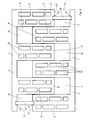
- the brick shown in the drawing in various embodiments essentially has two opposing end walls 1, which form the abutting surfaces for a laterally adjacent brick, and side walls 2 which run perpendicularly to the latter and form the free wall surface.
- the brick as can be seen in particular from FIG. 7, consists of two brick elements 3, 4, which essentially have the shape in cross section own a U-profile. These brick elements 3, 4 face each other with mutually facing profile legs, which are designed as side parts 5, 6 and form the side walls 2.
- the side parts 5, 6 each protrude into groove pockets 7, 8 of the other brick element, the groove pockets 7, 8 running parallel to the side parts 5, 6 adjoining them and extending in depth approximately to the profile back of the respective end wall 1 Brick elements 3, 4 extend.
- the groove pockets 7, 8 are each open to one side, that is to say not limited laterally.
- the side parts 6 are connected at one end to one of the brick elements 4 to the profile back forming the end wall 1 and both groove pockets 8 are arranged on the inside of the profile, while on the other brick element 3 the side parts 5 with the groove pocket 7 on the outside of the profile forming distance from the free end of the back wall 1 forming the profile back are connected.
- the side parts 5 of one brick element 3 engage between the side parts 6 of the other brick element 4, as a result of which both are mutually laterally guided.
- this requires two different brick elements 3, 4.
- the stone can be assembled from two identical brick elements 3, 4, which makes storage and production particularly easy.
- the cavity 9 formed between the side parts 5, 6 can, as shown in FIG. 7, be filled in any shape, for example, by loose filling bricks 10.
- the slat receptacles 12 between them for the slats 11 of the other brick element 3, 4 form.
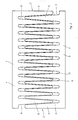
- the lamellae 11 and / or the side parts 5, 6 can, as can be seen from FIGS. 5 and 6, have a rectangular cross-section or, as shown in FIGS. 1 to 4, taper towards their free end .
- the lamellae 11 arranged in the central region of the brick element 3, 4 can also have a shorter length according to FIG. 3, whereby a mortar pocket is formed in the center of the stone in the case of brick elements which are pulled further apart in a manner not shown in detail.
- the end wall 1 of the brick can be provided on the outside with a toothing which is trapezoidal in cross section and which engages approximately positively in an abutting, appropriately shaped brick.
- the stones can be connected to one another without a lateral mortar joint.
- the individual slats 11 have a length such that the imaginary boundary surface spanned by their free ends forms a corresponding trapezoidal toothing. In this way, a single brick element 3, 4 can be placed directly with its lamellae in the trapezoidal toothing of an adjacent brick if, for example, only a narrow stone is required.
- the lamellae 11 are each arranged equidistantly, but there is also the possibility of arranging the lamellae 11 at different intervals in their direction of sequence.
- the slats 11 and / or the side parts 5, 6 can be provided with cavities 13 extending between the two bearing surfaces perpendicular to the end and side walls 1, 2.
- FIGS. 2 to 7 can in principle also be implemented for a brick in the shape according to FIG. 1, that is to say with differently designed brick elements 3, 4.
Landscapes
- Engineering & Computer Science (AREA)
- Architecture (AREA)
- Civil Engineering (AREA)
- Structural Engineering (AREA)
- Physics & Mathematics (AREA)
- Electromagnetism (AREA)
- Finishing Walls (AREA)
- Buildings Adapted To Withstand Abnormal External Influences (AREA)
Priority Applications (1)
| Application Number | Priority Date | Filing Date | Title |
|---|---|---|---|
| AT87100896T ATE52122T1 (de) | 1986-05-06 | 1987-01-23 | Mauerstein. |
Applications Claiming Priority (2)
| Application Number | Priority Date | Filing Date | Title |
|---|---|---|---|
| DE3615247 | 1986-05-06 | ||
| DE19863615247 DE3615247A1 (de) | 1986-05-06 | 1986-05-06 | Mauerstein |
Publications (3)
| Publication Number | Publication Date |
|---|---|
| EP0244555A2 true EP0244555A2 (fr) | 1987-11-11 |
| EP0244555A3 EP0244555A3 (en) | 1988-05-25 |
| EP0244555B1 EP0244555B1 (fr) | 1990-04-18 |
Family
ID=6300251
Family Applications (1)
| Application Number | Title | Priority Date | Filing Date |
|---|---|---|---|
| EP87100896A Expired - Lifetime EP0244555B1 (fr) | 1986-05-06 | 1987-01-23 | Brique murale |
Country Status (4)
| Country | Link |
|---|---|
| EP (1) | EP0244555B1 (fr) |
| AT (1) | ATE52122T1 (fr) |
| DE (1) | DE3615247A1 (fr) |
| ES (1) | ES2018484B3 (fr) |
Families Citing this family (2)
| Publication number | Priority date | Publication date | Assignee | Title |
|---|---|---|---|---|
| DE4128163A1 (de) * | 1991-08-24 | 1993-02-25 | Ulm Ziegel Kontor | Mauerziegel |
| DE102008039919A1 (de) | 2008-08-27 | 2010-03-04 | Udo Nagl | Vorgefertigte Ziegeleinheit |
Family Cites Families (5)
| Publication number | Priority date | Publication date | Assignee | Title |
|---|---|---|---|---|
| GB626692A (en) * | 1944-11-15 | 1949-07-20 | Francois Jerome Van Droogenbro | Building elements |
| US3518801A (en) * | 1968-09-30 | 1970-07-07 | George Redey | Adjustable construction joint strips |
| DE1951500A1 (de) * | 1968-10-16 | 1970-07-09 | Kalksandsteinwerke Niederlehme | Vorrichtung zur Gratentfernung an Griffoeffnungen von Mauersteinen |
| DE2618125C2 (de) * | 1976-04-26 | 1977-12-08 | Bruer, Manfred, Betriebsw.(grad.), 4300 Essen | Für die Mantelbetonbauweise bestimmtes großformatiges Schalungselement aus Hartschaumstoff |
| DE8437222U1 (de) * | 1984-12-20 | 1985-04-04 | Lüdenscheider Betonstein- und Mischwerke GmbH & Co KG, 5880 Lüdenscheid | Formstein |
-
1986
- 1986-05-06 DE DE19863615247 patent/DE3615247A1/de active Granted
-
1987
- 1987-01-23 ES ES87100896T patent/ES2018484B3/es not_active Expired - Lifetime
- 1987-01-23 EP EP87100896A patent/EP0244555B1/fr not_active Expired - Lifetime
- 1987-01-23 AT AT87100896T patent/ATE52122T1/de not_active IP Right Cessation
Also Published As
| Publication number | Publication date |
|---|---|
| ATE52122T1 (de) | 1990-05-15 |
| EP0244555B1 (fr) | 1990-04-18 |
| DE3615247C2 (fr) | 1989-04-06 |
| EP0244555A3 (en) | 1988-05-25 |
| DE3615247A1 (de) | 1987-11-12 |
| ES2018484B3 (es) | 1991-04-16 |
Similar Documents
| Publication | Publication Date | Title |
|---|---|---|
| DE7914521U1 (de) | Anordnung zum verbinden zweier profilteile, insbesondere rahmenteile von metallfenstern | |
| DE4108668B4 (de) | Schließzylinder-Schlüssel | |
| DE19807040B4 (de) | Wärmedämmverfüllziegel | |
| EP0244555B1 (fr) | Brique murale | |
| AT396702B (de) | Schalungsstein | |
| DE3100425C2 (de) | Mauerwerk und für den Zusammenhalt der Bausteine geeignetes Profilstreifensystem | |
| EP2014843A2 (fr) | Pierre taillée dotée de matériau d'isolation | |
| AT394222B (de) | Formstein, vorzugsweise aus beton | |
| DE19804729A1 (de) | Baustein, insbesondere auf der Basis zementgebundenen Blähtons | |
| DE29513122U1 (de) | Mauerstein | |
| CH675614A5 (fr) | ||
| DE19506073C1 (de) | Verfahren und Vorrichtung zum Verkleinern des Querschnitts der schnittseitigen Öffnungen von Lochungen in stranggepreßten Mauerziegel-Rohlingen oder im zugehörigen Preßstrang | |
| DE4007055C1 (en) | Window lintel or bridging piece - has pattern of through-slots allowing easy adjustment of size of window opening | |
| DE2458988C3 (de) | Anlegelatte zum Verlegen der untersten Reihe von Wandfliesen | |
| DE8513958U1 (de) | Effilierschere | |
| AT393000B (de) | Sprossenprofil | |
| CH662851A5 (de) | Baustein. | |
| DE3714590A1 (de) | Verfahren zum herstellen von stabfoermigen abstandshaltern aus zementgebundenem material, profil zur bildung derartiger abstandshalter sowie vorrichtung zum durchfuehren des verfahrens | |
| DE9400103U1 (de) | Mauerstein | |
| DE818106C (de) | Ziegel oder anderer Baukoerper | |
| DE1400829C (de) | Dübelstange | |
| DE19802270B4 (de) | Eckelement für die Verkleidung von Wänden oder dergleichen und Verfahren und Vorrichtung zur Herstellung solcher Eckelemente | |
| DE19530047A1 (de) | Mauerstein und Verfahren zur Herstellung | |
| DE29914583U1 (de) | Stein | |
| DE2631021A1 (de) | Fertigbauteilesatz zur erstellung von zwischenwaenden |
Legal Events
| Date | Code | Title | Description |
|---|---|---|---|
| PUAI | Public reference made under article 153(3) epc to a published international application that has entered the european phase |
Free format text: ORIGINAL CODE: 0009012 |
|
| AK | Designated contracting states |
Kind code of ref document: A2 Designated state(s): AT CH ES FR IT LI |
|
| PUAL | Search report despatched |
Free format text: ORIGINAL CODE: 0009013 |
|
| TCAT | At: translation of patent claims filed | ||
| AK | Designated contracting states |
Kind code of ref document: A3 Designated state(s): AT CH ES FR IT LI |
|
| 17P | Request for examination filed |
Effective date: 19880422 |
|
| 17Q | First examination report despatched |
Effective date: 19890615 |
|
| GRAA | (expected) grant |
Free format text: ORIGINAL CODE: 0009210 |
|
| AK | Designated contracting states |
Kind code of ref document: B1 Designated state(s): AT CH ES FR IT LI |
|
| REF | Corresponds to: |
Ref document number: 52122 Country of ref document: AT Date of ref document: 19900515 Kind code of ref document: T |
|
| ITF | It: translation for a ep patent filed | ||
| ET | Fr: translation filed | ||
| PLBE | No opposition filed within time limit |
Free format text: ORIGINAL CODE: 0009261 |
|
| STAA | Information on the status of an ep patent application or granted ep patent |
Free format text: STATUS: NO OPPOSITION FILED WITHIN TIME LIMIT |
|
| 26N | No opposition filed | ||
| ITTA | It: last paid annual fee | ||
| PGFP | Annual fee paid to national office [announced via postgrant information from national office to epo] |
Ref country code: ES Payment date: 19980113 Year of fee payment: 12 |
|
| PG25 | Lapsed in a contracting state [announced via postgrant information from national office to epo] |
Ref country code: ES Free format text: LAPSE BECAUSE OF EXPIRATION OF PROTECTION Effective date: 19990125 |
|
| REG | Reference to a national code |
Ref country code: ES Ref legal event code: FD2A Effective date: 20010601 |
|
| PGFP | Annual fee paid to national office [announced via postgrant information from national office to epo] |
Ref country code: FR Payment date: 20011003 Year of fee payment: 16 |
|
| PGFP | Annual fee paid to national office [announced via postgrant information from national office to epo] |
Ref country code: AT Payment date: 20011228 Year of fee payment: 16 |
|
| PGFP | Annual fee paid to national office [announced via postgrant information from national office to epo] |
Ref country code: CH Payment date: 20020123 Year of fee payment: 16 |
|
| PG25 | Lapsed in a contracting state [announced via postgrant information from national office to epo] |
Ref country code: AT Free format text: LAPSE BECAUSE OF NON-PAYMENT OF DUE FEES Effective date: 20030123 |
|
| PG25 | Lapsed in a contracting state [announced via postgrant information from national office to epo] |
Ref country code: LI Free format text: LAPSE BECAUSE OF NON-PAYMENT OF DUE FEES Effective date: 20030131 Ref country code: CH Free format text: LAPSE BECAUSE OF NON-PAYMENT OF DUE FEES Effective date: 20030131 |
|
| REG | Reference to a national code |
Ref country code: CH Ref legal event code: PL |
|
| PG25 | Lapsed in a contracting state [announced via postgrant information from national office to epo] |
Ref country code: FR Free format text: LAPSE BECAUSE OF NON-PAYMENT OF DUE FEES Effective date: 20030930 |
|
| REG | Reference to a national code |
Ref country code: FR Ref legal event code: ST |
|
| PG25 | Lapsed in a contracting state [announced via postgrant information from national office to epo] |
Ref country code: IT Free format text: LAPSE BECAUSE OF NON-PAYMENT OF DUE FEES;WARNING: LAPSES OF ITALIAN PATENTS WITH EFFECTIVE DATE BEFORE 2007 MAY HAVE OCCURRED AT ANY TIME BEFORE 2007. THE CORRECT EFFECTIVE DATE MAY BE DIFFERENT FROM THE ONE RECORDED. Effective date: 20050123 |