EP0243386B1 - Kabelloser lockenstab mit einer separaten heizstation - Google Patents
Kabelloser lockenstab mit einer separaten heizstation Download PDFInfo
- Publication number
- EP0243386B1 EP0243386B1 EP86905729A EP86905729A EP0243386B1 EP 0243386 B1 EP0243386 B1 EP 0243386B1 EP 86905729 A EP86905729 A EP 86905729A EP 86905729 A EP86905729 A EP 86905729A EP 0243386 B1 EP0243386 B1 EP 0243386B1
- Authority
- EP
- European Patent Office
- Prior art keywords
- curling
- mandrel
- curling iron
- heating
- heating assembly
- Prior art date
- Legal status (The legal status is an assumption and is not a legal conclusion. Google has not performed a legal analysis and makes no representation as to the accuracy of the status listed.)
- Expired - Lifetime
Links
- 238000010438 heat treatment Methods 0.000 title claims abstract description 122
- XEEYBQQBJWHFJM-UHFFFAOYSA-N Iron Chemical compound [Fe] XEEYBQQBJWHFJM-UHFFFAOYSA-N 0.000 claims description 152
- 229910052742 iron Inorganic materials 0.000 claims description 74
- 230000005294 ferromagnetic effect Effects 0.000 claims description 18
- 239000000463 material Substances 0.000 claims description 9
- 244000144725 Amygdalus communis Species 0.000 claims 1
- 239000003302 ferromagnetic material Substances 0.000 claims 1
- 230000037431 insertion Effects 0.000 claims 1
- 238000003780 insertion Methods 0.000 claims 1
- 238000004804 winding Methods 0.000 abstract description 53
- 230000005291 magnetic effect Effects 0.000 abstract description 13
- 235000000396 iron Nutrition 0.000 description 7
- 239000000696 magnetic material Substances 0.000 description 5
- 230000001681 protective effect Effects 0.000 description 5
- 230000008901 benefit Effects 0.000 description 3
- 230000015572 biosynthetic process Effects 0.000 description 3
- 238000007654 immersion Methods 0.000 description 3
- 230000007423 decrease Effects 0.000 description 2
- 230000001419 dependent effect Effects 0.000 description 2
- 230000000694 effects Effects 0.000 description 2
- 239000002655 kraft paper Substances 0.000 description 2
- 230000007257 malfunction Effects 0.000 description 2
- 230000035699 permeability Effects 0.000 description 2
- 230000009467 reduction Effects 0.000 description 2
- FAPWRFPIFSIZLT-UHFFFAOYSA-M Sodium chloride Chemical compound [Na+].[Cl-] FAPWRFPIFSIZLT-UHFFFAOYSA-M 0.000 description 1
- 230000009471 action Effects 0.000 description 1
- 229910052782 aluminium Inorganic materials 0.000 description 1
- XAGFODPZIPBFFR-UHFFFAOYSA-N aluminium Chemical compound [Al] XAGFODPZIPBFFR-UHFFFAOYSA-N 0.000 description 1
- 238000013459 approach Methods 0.000 description 1
- 238000007084 catalytic combustion reaction Methods 0.000 description 1
- 238000004140 cleaning Methods 0.000 description 1
- 238000002485 combustion reaction Methods 0.000 description 1
- 230000006735 deficit Effects 0.000 description 1
- 239000000446 fuel Substances 0.000 description 1
- 230000005484 gravity Effects 0.000 description 1
- 238000009434 installation Methods 0.000 description 1
- 239000011810 insulating material Substances 0.000 description 1
- 238000004519 manufacturing process Methods 0.000 description 1
- 229910052751 metal Inorganic materials 0.000 description 1
- 239000002184 metal Substances 0.000 description 1
- 238000007493 shaping process Methods 0.000 description 1
- 239000011232 storage material Substances 0.000 description 1
- 230000007704 transition Effects 0.000 description 1
Images
Classifications
-
- A—HUMAN NECESSITIES
- A45—HAND OR TRAVELLING ARTICLES
- A45D—HAIRDRESSING OR SHAVING EQUIPMENT; EQUIPMENT FOR COSMETICS OR COSMETIC TREATMENTS, e.g. FOR MANICURING OR PEDICURING
- A45D1/00—Curling-tongs, i.e. tongs for use when hot; Curling-irons, i.e. irons for use when hot; Accessories therefor
- A45D1/20—External heating means for curling-tongs or curling-irons
Definitions
- the invention relates to a wireless curling iron with a separate heating station.
- the invention relates to an indirectly heatable curling iron with the features of the preamble of the main claim.
- Indirectly heatable hair styling devices with a separate heating station are already known from US Pat. No. 3,415,254.
- a spring is inserted between the hair styling devices designed as curlers and the heating station, which causes the curler to be lifted off the heating station.
- In the edge area of the hair curler there is a bimetallic element which, when cold, engages in an annular groove of a heating mandrel of the heating station, provided that the hair curler is placed on the heating mandrel while overcoming the spring force.
- the bimetallic element undergoes deformation and disengages from the annular groove of the heating mandrel, so that the hair curler is lifted to a certain extent from the heating mandrel under the action of the spring force.
- a disadvantage of these curlers is the fact that the curler housing, which is otherwise filled with material with high thermal conductivity, has an air-filled space in the area of the bimetal element, so that a uniform operating temperature for the entire curler housing is not guaranteed.
- the bimetal spring is directly heated itself in the area of engagement in the annular groove of the heating mandrel, so that the temperature of the bimetal element does not correspond to the temperature of the hair curler itself.
- the temperature of the ferromagnetic body is not a direct measure of the actual temperature of the curling iron, so that switching off the heating at a predetermined temperature setpoint of the curling iron is not guaranteed.
- the user can recognize the operational readiness of the curling iron only by the lighting or extinguishing of an incandescent lamp, which in the event of a malfunction of the incandescent lamp leads to an impairment of the functionality of this arrangement.
- the curling iron according to the invention has the advantage that direct heating of the ferromagnetic body, the Curie temperature of which essentially corresponds to the desired temperature of the curling iron, is avoided.
- the fact that there is no direct thermal contact between a magnet attached to the heating block and the ferromagnetic body ensures that the ferromagnetic body essentially assumes the temperature of the winding mandrel of the curling iron.
- Changes to the rotationally symmetrical structure of the curling iron are not necessary, so that a constant thermal conductivity over the circumference of the curling iron is ensured.
- the special design of the housing of the heating station or a position-dependent switch in an advantageous embodiment means that incorrect positioning or Do not allow the heating station to operate if it is not positioned correctly.
- the first force is generated by a spring element ment generated, which is formed either as a spiral spring or as the winding mandrel of the curling iron wire element.
- Another very advantageous development of the invention consists in attaching several ferromagnetic bodies with different Curie temperatures over the length of the winding mandrel.
- the variable immersion depth of the winding dome in the heating station can then be used to set different target temperatures of the winding dome, in that, depending on the immersion depth, ferromagnetic bodies of different Curie temperatures are covered with the magnet attached in the heating block.
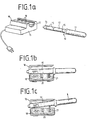
- FIG. 1 a shows a first exemplary embodiment of an indirectly heated curling iron 10 with a separate heating station 11.
- the curling iron 10 is composed in a known manner from a winding mandrel 12 and a handle part 13.
- a protective cap 14 is attached to the head part of the winding dome 12 and is made of a material with low thermal conductivity and thus does not heat up significantly.
- the winding mandrel 12 is made of heat-storing material and is wholly or partly interspersed with a magnetic material which changes its magnetic properties depending on the temperature (e.g. Thermoflux).
- the winding mandrel 12 has a ring 15 made of such a magnetic material in its central region. Of course, several such rings 15 can also be arranged on the winding dome 12.
- the at least one ring 15 is preferably arranged in the region of the two ends of the winding dome 12.
- the heating station 11 consists of a housing 16 which has a recess for introducing the winding mandrel 12.
- a heating block 18 shown schematically in FIG. 1 b, c, with a shape 17, which is heated by means of a resistance heater with a thermostat, a heater with a PTC resistor or the like.
- the invention is not limited to mains powered, i.e. electrical heating stations limited, but also applicable for, for example, gas-heated heating stations.
- Accidental touching of the heating block 18 can be avoided by a pivotable grid 19 covering the recess of the housing 16 and the shape 17 or similar protective measures.
- At least one permanent magnet 20 and one spring element 21 are embedded in the heating block 18.
- the permanent magnet 20 is positioned in the heating block in such a way that it coincides with the ring 15 attached to the winding mandrel 12 of the curling iron 10 as soon as the winding mandrel 12 has been properly inserted into the formation 17 of the heating station 11.
- the ring 15 has normal magnetic properties, so that with a suitable arrangement of the poles of the ring 15 and the permanent magnet 20 an attractive force occurs between the winding mandrel 12 and the heating block 18. This magnetic force outweighs that, essentially in the opposite direction, i.e.
- the winding mandrel 12 due to the predominant magnetic attraction in intimate thermal contact with the Schubbck 18 of the heating station 11, preferably at heating temperatures in the range between 200 ° C and 500 ° C, especially at about 250 ° C - 350 ° C is operated.
- the curling iron 10 rapidly heats up.
- the temperature of the heating block 18 changes only insignificantly during the heating process, since the heating output of the heating block 18 can be adapted to the respective requirements by means of a temperature control.
- the magnetic properties of the material of the ring 15 determine the desired temperature value of the winding dome 12 of the curling iron 10.
- the permeability of the ring material decreases. This leads to a reduction in the magnetic holding forces between the winding mandrel 12 and the heating block 18, so that finally the influence of the repulsive spring force of the spring element 21 takes over and the winding mandrel 12 from the heating block 18th takes off at the end of the heating process.
- the curling iron 10 is now ready for use and can be used for a longer period of time for hair styling.
- the temperature setpoint of the winding mandrel 12 is determined by a suitable selection of the ring material, preferably in the range between 100 ° C. and 200 ° C., in particular approximately 150 ° C., while the temperature of the heating block 18 is in particular approximately 100 ° C.-200 ° C is set higher. This measure ensures that the curling iron 10 heats up very quickly.
- the curling iron 10 has a very simple structure, can be cleaned quickly and easily and, due to the lack of electrically or mechanically sensitive components, has a very high level of operational reliability.
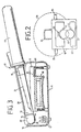
- FIG. Shown is the front view of the heating station 11, in which the winding mandrel 12 is inserted for heating.
- the heating block 18 is arranged in the upper region of the housing 16 of the heating station 11.
- the winding mandrel 12 of the curling iron 10 is inserted in the corresponding shape 17 of the heating block 18 hanging.
- the holding forces are applied by the magnetic effect between the at least one permanent magnet 20 in the heating block 18 and the magnetic material introduced into the winding mandrel 12.
- the force component acting essentially opposite to these magnetic forces results from the gravitational force.
- the curling iron 10 simply falls down from the heating block 18 after reaching the temperature setpoint value onto a bearing 22 preferably made of heat-resistant and heat-insulating material.
- a bearing 22 preferably made of heat-resistant and heat-insulating material.
- which in the present exemplary embodiment has a shape 23 for receiving the winding mandrel 12 of the curling iron 10.
- any spring elements for lifting the winding dome 12 from the heating block 18 can be dispensed with. However, care must be taken to ensure that the heating station 11 cannot be operated in an improper position.
- Improper positioning is particularly the case when the heating station 11 is set up in the side or head position, since then the force components of the releasing or attracting forces are aligned either parallel or perpendicular to one another and, in extreme cases, the winding mandrel 12 cannot be lifted off the heating block 18 .
- Such incorrect handling can be excluded by a suitable design of the housing 16 of the heating station 11.
- FIG. 2 shows some examples of this, namely attaching a handle 24 to the top or a strip 25 to the side parts of the housing 16.
- a partially cylindrical shape for the upper part of the housing 16 would also be conceivable, as shown by the dashed line Line 26 indicated. If you also ensure that the center of gravity of the heating station 11 with an inserted curling iron 10 comes to lie between the central axis of the partial cylinder and a base plate 27 of the housing 16, an incorrect installation of the housing 16 is made impossible because of the unstable position.
- FIG 3 another embodiment of the curling iron according to the invention is shown in detail.
- the heating station 11 is shown in longitudinal section with the winding mandrel 12 inserted but lifted off.
- the curling iron 10, which in the present example has an curling scissor blade 28, is mounted with its protective cap 14 in a shoulder 29 integrally formed in the interior of the housing 16 such that it can be pivoted or pivoted.
- a rod 30 is provided above the shoulder 29, which covers the protective cap 14 of the inserted curling iron 10.
- A approximately in the edges of a Aufschikkeidorn 12 comprising half-shell reshaped spring element 21, which is fixed in the area of the cap 14 of the inserted curling iron 10 on the heating station 11 and includes the winding mandrel 12 in the transition area to the handle 13 over about half the circumference, produces force component detaching the winding mandrel 12 from the heating block 18.
- the height of the shoulder 29 is fixed relative to the shape 17 of the heating block 18 in such a way that the winding dome 12 does not have any direct thermal contact with the heating block 18 at any point over its entire length in the raised state.
- the magnetic force is generated by means of a ring 15 arranged in the area of the winding mandrel 12 close to the handle or a different introduction of the magnetic material and the magnet 20 arranged in the heating block 18.
- the magnet 20 is slightly recessed in the shape 17 of the heating block 18, so that between the ring 15 of the winding mandrel 12 and the magnet 20 there is also a distance indicated by arrows 31 when the curling iron 10 for heating in the formation 17 is attached.
- This measure allows the ring 15 to be directly heated via the heating block 18 and the magnet 20 acting as a thermal bridge without a substantial reduction in the magnetic force effect. This ensures that the ring temperature is essentially determined by the temperature of the winding mandrel 12 and not by the tem temperature of the heating block 18 is determined.
- a good thermal contact between the winding mandrel 12 and the heating block 31 is to be ensured by means of the rod 30 above the shoulder 29.
- the rod 30 is therefore arranged at such a height with respect to the protective cap 14 of the inserted curling iron 10 that it is not possible to lift off the front part of the winding mandrel 12 during the heating phase.
- the lifting height of the winding mandrel 12 determined by the spring constant of the spring element 21 after the end of the heating process is determined in a very advantageous manner in such a way that the heat balance of the winding mandrel is balanced in the raised state.
- a constant temperature of the winding mandrel 12 is ensured even if it is in the heating station 11 in the raised state for a longer time.
- the height to be set individually depends on the individual case and must be determined individually by the responsible specialist.
- winding mandrel 12 from metal, preferably aluminum.
- the formation of the winding mandrel 12 as a latent heat store using storage materials such as wax, saline solution or the like can also be useful for extending the period of use of the curling iron 10.
- the invention can be further developed so that, for example, the heat of combustion is used for the catalytic combustion of a gaseous fuel for heating.
- a further, very advantageous embodiment of the invention provides for the attachment of at least two ferromagnetic bodies with different Curie temperatures to the winding mandrel 12 of the curling iron 10.
- a user-selectable immersion depth of the winding mandrel 12 in the heating block 18 there is the possibility of having at least one of the ferromagnetic bodies of different Curie temperatures come to coincide with the permanent magnet 20.
- This enables a setpoint temperature of the winding mandrel 12 which can be selected within wide limits, so that this temperature can be individually adapted to the user's hair condition.
Landscapes
- General Induction Heating (AREA)
Description
- Die Erfindung betrifft einen kabellosen Lockenstab mit eines separaten Heizstation.
- Die Erfindung geht aus von einem indirekt beheizbaren Lockenstab mit den Merkmalen des Oberbegriffs des Hauptanspruchs. Bereits aus der US-PS 3 415 254 sind indirekt beheizbare Haarformungsgeräte mit einer separaten Heizstation bekannt. Zwischen den als Lockenwicklern ausgebildetn Haarformungsgeräten und der Heizstation ist eine Feder eingesetzt, die ein Abheben des Lockenwicklers von der Heizstation bewirkt. Im Randbereich des Lockenwicklers befindet sich ein Bimetallelement, welches im kalten Zustand in eine Ringnut eines Heizdorns der Heizstation eingreift, sofern der Lockenwickler unter Überwindung der Federkraft auf den Heizdorn aufgesetzt wird. Nachdem der Lockenwickler die Betriebstemperatur erreicht hat, erfährt das Bimetallelement eine Verformung und rastet aus der Ringnut des Heizdorns aus, so daß der Lockenwickler unter der Wirkung der Federkraft um ein gewisses Maß von dem Heizdorn abgehoben wird. Nachteilig an diesen Lockenwicklern ist die Tatsache, daß das ansonsten mit Material hoher Wärmeleitfähigkeit ausgefüllte Lockenwicklergehäuse im Bereich des Bimetallelements einen luftgefüllten Raum aufweist, so daß eine gleichmäßige Betriebstemperatur für das gesamte Lockenwicklergehäuse nicht gewährleistet ist. Darüber hinaus wird die Bimetallfeder im Bereich des Eingriffs in die Ringnut des Heizdorns unmittelbar selbst aufgeheizt, so daß die Temperatur des Bimetallelements nicht der Temperatur des Lockenwicklers an sich entspricht. Ein reproduzierbares Auslösen des Bimetallelements bei einem vorgegebenen Temperatur-Sollwert des Lockenwicklers ist durch diese konstruktiven Maßnahmen nicht gegeben.
- Auch aus der US-PS 4 499 355 ist ein indirekt beheizter Lockenwickler oder Lockenstab bekannt, der an einem Ende einen ferromagnetischen Körper aufweist, dessen Curie-Temperatur mit dem Temperatur-Sollwert des Lockenstabes übereinstimmt. In der Heizstation ist ein Permanentmagnet angeordnet, der dem ferromagnetischen Körper des Lockenstabes gegenüberliegt und mit einem Kippschalter verbunden ist. Hat der Lockenstab die Betriebstemperatur erreicht, verliert der ferromagnetische Körper im Lockenstab seine magnetischen Eigenschaften, so daß der in der Heizstation angebrachte Magnet herabfällt und einen Schalter zur Unterbrechung der Stromzufuhr zur Heizung betätigt. Allerdings wird der im Lockenstab angebrachte, ferromagnetische Körper von der Hochfrequenzheizung der Heizstation unmittelbar selbst erwärmt. Auch in diesem Ausführungsbeispiel ist die Temperatur des ferromagnetischen Körpers nicht unmittelbar ein Maß für die tatsächliche Temperatur des Lockenstabes, so daß ein Abschalten der Heizung bei einem vorgegebenen Temperatur-Sollwert des Lockenstabes nicht gewährleistet ist. Im übrigen kann der Benutzer die Betriebsbereitschaft des Lockenstabes lediglich an dem Aufleuchten oder Erlöschen einer Glühlampe erkennen, was im Falle einer Störung der Glühlampe zu einer Beeinträchtigung der Funktionsfähigkeit dieser Anordnung führt.
- Mit Ausnahme dieser Einschränkungen weist dieses Konzept eines indirekt beheizten Lockenstabes wesentliche Vorteile gegenüber den herkömmlichen, mit einer direkten Heizung ausgerüsteten Lockenstäben auf: Zum einen entfällt das normalerweise vorhandene Netzkabel, welches während der Handhabung der Lockenstäbe im allgemeinen sehr hinderlich ist. Die Reinigung von indirekt beheizten Lockenstäben ist andererseits sehr unproblematisch, da keine elektrischen oder mechanisch empfindlichen Bauteile am Lockenstab vorhanden sind. Darüber hinaus werden mögliche Unfallursachen bei der Handhabung von direkt beheizbaren, elektrischen Lockenstäben, z. B. in Feuchträumen wie Badezimmer und ähnlichem durch den Einsatz von indirekt beheizbaren Lockenstäben völlig ausgeschlossen.
- Es ist daher Aufgabe der Erfindung, einen indirekt beheizbaren Lockenstab mit einer separaten Heizstation zu schaffen, der sich durch eine sichere Handhabung auszeichnet, wobei der Lockenstab eine homogene Betriebstemperatur aufweist, die äußerst genau und reproduzierbar einstellbar ist.
- Diese Aufgabe wird durch einen indirekt beheizbaren Lockenstab mit einer separaten Heizstation mit den Merkmalen des Hauptanspruchs gelöst.
- Der erfindungsgemäße Lockenstab weist den Vorteil auf, daß eine direkte Aufheizung der ferromagnetischen Körpers, dessen Curie-Temperatur mit der Soll-Temperatur des Lockenstabes im wesentlichen übereinstimmt, vermieden wird. Dadurch, daß zwischen einem am Heizblock angebrachten Magneten und dem ferromagnetischen Körper kein direkter Wärmekontakt besteht, ist gewährleistet, daß der ferromagnetische Körper im wesentlichen die Temperatur des Aufwickeldorns des Lockenstabes annimmt. Veränderungen am rotationssymmetrischen Aufbau des Lockenstabes sind nicht erforderlich, so daß eine konstante Wärmeleitfähigkeit über den Umfang des Lockenstabes gewährleistet ist. Weiterhin hat es sich als vorteilhaft erwiesen, die magnetischen Haltemittel In der Umgebung wenigstens eines der Randbereiche eines Heizblocks der Heizstation bzw. des Aufwickeldoms des Lockenstabes anzuordnen, wodurch der oben erwähnte Effekt unterstützt wird.
- Zur Vermeidung von möglichen Störfällen bei unsachgemäßer Positionierung der Heizstation, insbesondere bei einer Aufstellung in einer Seiten- bzw. Kopflage, sind durch die besondere Ausgestaltung des Gehäuses der Heizstation bzw. durch einen lageabhängigen Schalter in vorteilhafter Ausgestaltung Mittel angegeben, die eine falsche Positionierung bzw. einen Betrieb der Heizstation bei unsachgemäßer Positionierung nicht zulassen.
- Gemäß einer weiteren Ausgestaltung der Erfindung wird die erste Kraft durch ein Federelement erzeugt, das entweder als Spiralfeder oder als den Aufwickeldorn des Lockenstabes aufnehmendes Drahtelement ausgebildet ist.
- Darüber hinaus hat es sich als vorteilhaft erwiesen, den Lockenstab an seinem Kopfende derart kippbar zu lagern, daß der Aufwickeldorn des Lockenstabes nach Beendigung des Aufheizvorganges von dem wenigstens einem Federelement völlig vom Heizblock der Heizstation abgehoben wird.
- Eine ebenfalls sehr vorteilhafte Weiterbildung der Erfindung besteht darin, über die Länge des Aufwickeidorns mehrere ferromagnetische Körper mit unterschiedlichen Curie-Temperaturen anzubringen. Über die variierbare Eintauchtiefe des Aufwickeldoms in die Heizstation lassen sich dann unterschiedliche Soll-Temperaturen des Aufwickeldoms einstellen, indem je nach Eintauchtiefe ferromagnetische Körper verschiedener Curie-Temperatur mit dem in dem Heizblock angebrachten Magneten zur Deckung kommen. Durch diese Maßnahmen ist beispielsweise eine Anpassung des Temperatur-Sollwertes des Heizdorns an unterschiedliche Feuchtigkeitsgrade oder Haartypen möglich.
- Weitere Vorteile der Erfindung ergeben sich aus der nachfolgenden Beschreibung der Ausführungsbeispiele in Verbindung mit den Zeichnungen. Es zeigen:
- Figur 1 a ein Ausführungsbeispiel des erfindungsgemäßen Lockenstabes,
- Figur 1b die Positionierung des Lockenstabes während des Aufheizvorganges vor Erreichen der Soll-Temperatur,
- Figur 1c die Positionierung des Lockenstabes nach Beendigung des Aufheizvorganges, d. h. nach Erreichen der Soll- Temperatur,
- Figur 2 eine weitere Ausführungsform des erfindungsgemäßen Lockenstabes, bei der als weitere Kraft die Gravitationskraft ausgenutzt wird und
- Figur 3 eine dritte Ausführungsform des erfindungsgemäßen Lockenstabes, bei der als weitere Kraft die Federkraft eines den Aufnahmedorn des Lockenstabes aufnehmendes Drahtelementes ausgenutzt wird.
- In Figur 1a ist ein erstes Ausführungsbeispiel eines indirekt beheizten Lockenstabes 10 mit einer separaten Heizstation 11 dargestellt. Der Lockenstab 10 setzt sich in bekannter Weise aus einem Aufwickeldorn 12 und einem Griffteil 13 zusammen. Am Kopfteil des Aufwickeldoms 12 ist eine Schutzkappe 14 befestigt, die aus einem Material geringer Wärmeleitfähigkeit hergestellt ist und sich somit nicht wesentlich aufheizt. Der Aufwickeldorn 12 besteht aus wärmespeicherndem Material und ist ganz oder teilweise mit einem magnetischen Material, weiches seine magnetischen Eigenschaften in Abhängigkeit von der Temperatur ändert (z. B. Thermoflux), durchsetzt. Im Ausführungsbeispiel der Figur 1 a weist der Aufwickeidorn 12 in seinem Mittelbereich einen Ring 15 aus einem derartigen magnetischen Material auf. Natürlich können auch mehrere derartige Ringe 15 am Aufwickeldom 12 angeordnet sein. Vorzugsweise ist der wenigstens eine Ring 15 im Bereich der beiden Enden des Aufwickeldoms 12 angeordnet.
- Die Heizstation 11 besteht aus einem Gehäuse 16, welches eine Ausnehmung zur Einbringung des Aufwickeldorns 12 aufweist. Im Gehäuse 16 befindet sich ein in Figur 1 b, c schematisch dargestellter Heizblock 18 mit einer Ausformung 17, der mittels einer Widerstandsheizung mit Thermostat, einer Heizung mit einem PTC-Widerstand oder ähnlichem aufgeheizt wird. Die Erfindung ist nicht ausschließlich auf netzbetriebene, d.h. elektrische Heizstationen beschränkt, sondern auch für beispielsweise gasbeheizte Heizstationen anwendbar. Durch ein, die Ausnehmung des Gehäuses 16 und die Ausformung 17 abdeckendes, schwenkbares Gitter 19 oder ähnliche Schutzmaßnahmen lassen sich zufällige Berührungen des Heizblocks 18 vermeiden.
- Wie aus Figur 1b, c ersichtlich ist, sind im Heizblock 18 wenigstens ein Permanentmagnet 20 und ein Federelement 21 eingelassen. Der Permanentmagnet 20 ist im Heizblock derart positioniert, daß er mit dem am Aufwickeldorn 12 des Lockenstabes 10 angebrachten Ring 15 zur Deckung kommt, sobald der Aufwickeldorn 12 sachgemäß in die Ausformung 17 der Heizstation 11 eingebracht ist. Für Lockenstabtemperaturen unterhalb eines vorbestimmten Temperatur-Sollwertes weist der Ring 15 normale magnetische Eigenschaften auf, so daß bei geeigneter Anordnung der Pole des Ringes 15 und des Permantentmagneten 20 eine anziehende Kraft zwischen dem Aufwickeldorn 12 und dem Heizblock 18 auftritt. Diese magnetische Kraft überwiegt die, im wesentlichen in entgegengesetzter Richtung, d.h. abstoßend wirkende Kraft des Federelements 21, das im vorliegenden Ausführungsbeispiel als Spiralfeder ausgebildet ist. Dies hat zur Folge, daß der Aufwickeldorn 12 aufgrund der überwiegenden magnetischen Anziehungskraft in innigem Wärmekontakt mit dem Heizbbck 18 der Heizstation 11, die vorzugsweise bei Heiztemperaturen im Bereich zwischen 200° C und 500° C, insbesondere bei ca. 250° C - 350° C betrieben wird, steht. Infolgedessen tritt eine rasche Erwärmung des Lockenstabes 10 auf. Die Temperatur des Heizblocks 18 ändert sich während des Aufheizvorganges nur unwesentlich, da die Heizleistung des Heizblocks 18 mittels einer Temperaturregelung an die jeweiligen Erfordernisse anpaßbar ist.
- Die magnetischen Eigenschaften des Materials des Ringes 15 bestimmen den Temperatur-Sollwert des Aufwickeldoms 12 des Lockenstabes 10. Nähert sich die Temperatur des Ringmaterials der Curie-Temperatur, so läßt die Permeabilität des Ringmaterials nach. Dies führt zu einer Verringerung der magnetischen Haltekräfte zwischen Aufwickeidorn 12 und Heizblock 18, so daß schließlich der Einfluß der abstoßenden Federkraft des Federelements 21 Oberhand gewinnt und den Aufwickeldom 12 von dem Heizblock 18 zur Beendigung des Aufheizvorganges abhebt.
- Der Lockenstab 10 ist nun gebrauchsbereit und kann für eine längere Zeitdauer zur Haarformung eingesetzt werden. Der Temperatur-Sollwert des Aufwickeidorns 12 wird durch eine geeignete Auswahl des Ringmaterials bevorzugt im Bereich zwischen 100° C und 200° C, insbesondere auf ca. 150° C festgelegt, während die Temperatur des Heizblocks 18 um insbesondere ca. 100° C - 200° C höhes eingestellt wird. Durch diese Maßnahme wird ein sehr schnelles Aufheizen des Lockenstabes 10 gewährleistet. Der Lockenstab 10 ist dazu sehr einfach aufgebaut, schnell und problemlos zu reinigen und weist aufgrund fehlender elektrischer bzw. mechanisch empfindlicher Bauelemente eine sehr hohe Betriebssicherheit auf.
- In Figur 2 ist eine weitere Ausführungsform der Erfindung schematisch dargestellt. Gezeigt ist die Frontansicht auf die Heizstation 11, in die der Aufwicketdorn 12 zur Aufheizung eingebracht ist. Im Gegensatz zum Ausführungsbeispiel der Figur 1 ist der Heizblock 18 im oberen Bereich des Gehäuses 16 der Heizstation 11 angeordnet. Der Aufwickeldorn 12 des Lockenstabes 10 ist in die entsprechende Ausformung 17 des Heizblocks 18 hängend eingebracht. Die Haltekräfte werden durch die magnetische Wirkung zwischen dem wenigstens einen Permanentmagneten 20 im Heizblock 18 und dem in den Aufwickeldorn 12 eingebrachten magnetischen Material aufgebracht. Die zu diesen magnetischen Kräften im wesentlichen entgegengesetzt wirkende Kraftkomponente resultiert aus der Gravitationskraft.
- Läßt die Permeabilität des im Aufwickeldiorn 12 eingebrachten magnetischen Materials mit wachsender Temperatur, wie schon ausführlich beschrieben, nach, so fällt der Lockenstab 10 nach Erreichen des Temperatur-Sollwertes einfach von dem Heizblock 18 herunter auf eine vorzugsweise aus hitzebeständigem und wärmeisolierendem Material hergestellten Lagerung 22, die im vorliegenden Ausführungsbeispiel eine Ausformung 23 zur Aufnahme des Aufwickeidorns 12 des Lockenstabes 10 aufweist. Bei dieser Ausführungsform kann auf jegliche Federelemente zum Abheben des Aufwicketdoms 12 vom Heizblock 18 verzichtet werden. Es ist jedoch dafür Sorge zu tragen, daß ein Betrieb der Heizstation 11 in einer unsachgemäßen Positionierung nicht möglich ist. Eine unsachgemäße Positionierung liegt insbesondere dann vor, wenn die Heizstation 11 in Seiten- oder Kopflage aufgestellt wird, da dann die Kraftkomporienten der ablösenden bzw. anziehenden Kräfte entweder parallel oder senkrecht zueinander ausgerichtet sind und im Extremfall ein Abheben des Aufwickeldorns 12 vom Heizblock 18 ausgeschlossen ist. Eine solchermaßen falsche Handhabung kann durch eine geeignete Gestaltung des Gehäuses 16 der Heizstation 11 ausgeschlossen werden. In Figur 2 sind hierfür beispielhaft einige Möglichkeiten dargestellt, nämlich eine Anbringung eines Griffs 24 an der Oberseite bzw. je einer Leiste 25 an den Seitenteilen des Gehäuses 16. Denkbar wäre auch eine teilzylindrische Formgebung für den oberen Teil des Gehäuses 16, wie durch die gestrichefte Linie 26 angedeutet. Sorgt man zusätzlich dafür, daß der Schwerpunkt der Heizstation 11 mit eingelegtem Lockenstab 10 zwischen der Mittelachse des Teilzylinders und einer Bodenplatte 27 des Gehäuses 16 zu liegen kommt, so wird eine falsche Aufstellung des Gehäuses 16 wegen der labilen Lage unmöglich gemacht.
- Sollte aus Gründen der ästhetischen Formgestaltung eine solchermaßen zweckbedingte Formgebung des Gehäuses 16 nicht zum Tragen kommen, besteht darüber hinaus die Möglichkeit, mittels eines lageabhängigen elektrischen Schalters den Heizstromkreis zum Heizblock 18 zu unterbrechen, falls die Heizstation 11 nicht sachgemäß auf ihrer Bodenplatte 27 aufgestellt wird.
- In Figur 3 ist ein weiteres Ausführungsbeispiel des erfindungsgemäßen Lockenstabes detailliert wiedergegeben. Aus Gründen der Übersichtlichkeit ist die Heizstation 11 Im Längsschnitt mit eingelegtem, aber abgehobenen Aufwickceldiorn 12 dargestellt. Der im vorliegenden Beispiel ein Ondulierscherenblatt 28 aufweisende Lockenstab 10 ist mit seiner Schutzkappe 14 in einer, im Inneren des Gehäuses 16 angeformten Schulter 29 kipp- bzw. schwenkbar gelagert. Zur Sicherung gegen ein Herauskippen des Lockenstabes 10 aus der Heizstation 11 ist ein Stab 30 oberhalb der Schulter 29 vorgesehen, der die Schutzkappe 14 des eingelegten Lockenstabes 10 überfaßt. Ein, in etwa den Rändern einer den Aufwikkeidorn 12 umfassenden Halbschale nachgeformtes Federelement 21, weiches im Bereich der Kappe 14 des eingelegten Lockenstabes 10 an der Heizstation 11 befestigt ist und den Aufwickeidorn 12 im Übergangsbereich zum Griff 13 über etwa den halben Umfang umfaßt, erzeugt die den Aufwickeldorn 12 von dem Heizblock 18 ablösende Kraftkomponente. Die Höhe der Schulter 29 wird relativ zur Ausformung 17 des Heizblocks 18 derart festgelegt, daß der Aufwickeldom 12 im abgehobenen Zustand an keinem einzigen Punkt über seine gesamte Länge einen direkten Wärmekontakt zum Heizblock 18 aufweist.
- Die magnetische Kraft wird mittels eines im griffnahen Bereich des Aufwickeldorns 12 angeordneten Ringes 15 bzw. einer andersartigen Einbringung des magnetischen Materials und dem im Heizblock 18 angeordneten Magneten 20 erzeugt. In vorteilhafter Ausgestaltung der Erfindung ist der Magnet 20 leicht versenkt in der Ausformung 17 des Heizblocks 18 angebracht, so daß zwischen dem Ring 15 des Aufwickeldorns 12 und dem Magnet 20 auch dann ein durch Pfeile 31 gekennzeichneter Abstand vorliegt, wenn der Lockenstab 10 zum Aufheizen in die Ausformung 17 angebracht ist. Durch diese Maßnahme läßt sich ohne wesentliche Verringerung der magnetischen Kraftwirkung ein direktes Aufheizen des Ringes 15 über den Heizblock 18 und den als Wärmebrücke wirkenden Magneten 20 erreichen. Dadurch ist gewährleistet, daß die Ringtemperatur im wesentlichen durch die Temperatur des Aufwickceldorns 12 und nicht durch die Temperatur des Heizblocks 18 bestimmt ist.
- Mittels des Stabes 30 oberhalb der Schulter 29 soll ein guter Wärmekontakt zwischen dem Aufwickeldorn 12 und dem Heizblock 31 gewährleistet werden. Der Stab 30 ist daher in einer derartigen Höhe in bezug auf die Schutzkappe 14 des eingelegten Lockenstabes 10 angeordnet, daß ein Abheben des Vorderteils des Aufwickeldorns 12 während der Aufheizphase nicht möglich ist.
- Die Funktionsweise dieser Anordnung gemäß Figur 3 stimmt weitgehend mit der der Figur 1 überein.
- Die durch die Federkonstante des Federelements 21 bestimmte Abhebehöhe des Aufwickeldorns 12 nach Beendigung des Aufheizvorganges wird in sehr vorteilhafter Weise derart festgelegt, daß im abgehobenen Zustand der Wärmehaushalt des Aufwickeldorns ausgeglichen ist. Dies heißt, daß die vom abgehobenen Aufwickeldorn 12 an die Umgebung abgegebene Wärmemenge im wesentlichen mit der vom Aufwickeldom 12 Indirekt, d.h. über das Luftpolster zwischen Heizblock 18 und Aufwickeldorn 12 aufgenommene Wärmemenge übereinstimmt. Hierdurch ist eine konstante Temperatur des Aufwickeldorns 12 auch dann gewährleistet, wenn dieser sich längere Zeit im abgehobenen Zustand in der Heizstation 11 befindet. Die jeweils individuell einzustellende Höhe hängt vom Einzelfall ab und ist vom zuständigen Fachmann jeweils individuell zu ermitteln.
- Neben diesen ausführlich beschriebenen Ausführungsbeispielen sind weitere Ausgestaltungen möglich. Beispielsweise hat es sich vorteilhaft erwiesen, den Aufwickeldorn 12 aus Metall, vorzugsweise Aluminium, herzustellen. Auch die Ausbildung des Aufwikkeldorns 12 als Latentwärmespeicher, unter Verwendung von Speichermaterialien, wie Wachs, Salzlösung oder ähnlichem kann zur Verlängerung der Benutzungszeit des Lockenstabes 10 von Nutzen sein.
- Für ein netzunabhängiges Betreiben der Heizstation 11 läßt sich die Erfindung dahingehend weiter entwickien, daß zur Aufheizung beispielsweise die Verbrennungswärme bei der katalytischen Verbrennung eines gasförmigen Brennstoffs ausgenutzt wird.
- Darüber hinaus besteht eine vorteilhafte Ausgestaltung der Erfindung in der Verwendung von zwei oder mehreren Lockenstäben in Verbindung mit einer einzigen Heizstation, so daß durch abwechselndes Aufheizen der verschiedenen Lockenstäbe immer ein auf Solltemperatur bzw. Arbeitstemperatur befindlicher Lockenstab zur Verfügung steht.
- Eine weitere, sehr vorteilhafte Ausgestaltung der Erfindung sieht die Anbringung von wenigstens zwei ferromagnetischen Körpern mit unterschiedlicher Curie-Temperatur am Aufwickeidorn 12 des Lockenstabes 10 vor. Durch eine vom Benutzer wählbare Eintauchtiefe des Aufwickeldorns 12 in den Heizblock 18 besteht die Möglichkeit, jeweils wenigstens einen der ferromagnetischen Körper unterschiedlicher Curie-Temperatur mit dem Permanentmagneten 20 zur Deckung kommen zu lassen. Hierdurch wird eine in weiten Grenzen wählbare Sollwert-Temperatur des Aufwickeldorns 12 ermöglicht, so daß eine individuelle Anpassung dieser Temperatur an den Haarzustand des Benutzers gegeben ist.
Claims (12)
Applications Claiming Priority (2)
| Application Number | Priority Date | Filing Date | Title |
|---|---|---|---|
| DE19853538545 DE3538545A1 (de) | 1985-10-30 | 1985-10-30 | Kabelloser lockenstab mit einer separaten heizstation |
| DE3538545 | 1985-10-30 |
Publications (2)
| Publication Number | Publication Date |
|---|---|
| EP0243386A1 EP0243386A1 (de) | 1987-11-04 |
| EP0243386B1 true EP0243386B1 (de) | 1990-02-28 |
Family
ID=6284788
Family Applications (1)
| Application Number | Title | Priority Date | Filing Date |
|---|---|---|---|
| EP86905729A Expired - Lifetime EP0243386B1 (de) | 1985-10-30 | 1986-09-26 | Kabelloser lockenstab mit einer separaten heizstation |
Country Status (4)
| Country | Link |
|---|---|
| US (1) | US4803341A (de) |
| EP (1) | EP0243386B1 (de) |
| DE (2) | DE3538545A1 (de) |
| WO (1) | WO1987002555A1 (de) |
Cited By (1)
| Publication number | Priority date | Publication date | Assignee | Title |
|---|---|---|---|---|
| DE19504199A1 (de) * | 1995-02-09 | 1996-05-15 | Rudolf Bauer | Scherenheizgerät |
Families Citing this family (48)
| Publication number | Priority date | Publication date | Assignee | Title |
|---|---|---|---|---|
| US5149942A (en) * | 1990-08-09 | 1992-09-22 | Garrett James A | Hot mirror to prevent condensation in humid environments |
| USD332670S (en) | 1990-10-09 | 1993-01-19 | Mcfarland James G | Hair curling iron support stand |
| US5798500A (en) * | 1993-08-10 | 1998-08-25 | Stillwagon, Jr.; Ross I. | Curling iron stove with internal cavity with electric heater positioned therebelow |
| USD371220S (en) | 1994-10-31 | 1996-06-25 | Behrens Kathie J | Curling iron holder |
| USD385705S (en) * | 1995-10-23 | 1997-11-04 | Braun Aktiengesellschaft | Cover for a curling brush |
| USD391019S (en) | 1995-10-23 | 1998-02-17 | Braun Aktiengesellschaft | Combined curling brush with cover |
| US5749379A (en) * | 1996-04-25 | 1998-05-12 | Golden Supreme, Inc. | Non-numeric temperature indicating method for a hair styling iron |
| US5713379A (en) * | 1996-09-25 | 1998-02-03 | Collins; Joyce E. | Curling iron system with a friction element to generate heat |
| US5785064A (en) * | 1997-03-07 | 1998-07-28 | Simpson; Timothy A. | High temperature externally heated hair-styling devices |
| US7458940B2 (en) * | 2000-11-06 | 2008-12-02 | Suros Surgical Systems, Inc. | Biopsy apparatus |
| US6758824B1 (en) * | 2000-11-06 | 2004-07-06 | Suros Surgical Systems, Inc. | Biopsy apparatus |
| WO2002069808A2 (en) * | 2000-11-06 | 2002-09-12 | Suros Surgical Systems, Inc. | Biopsy apparatus |
| US7009519B2 (en) * | 2002-11-21 | 2006-03-07 | S.C. Johnson & Sons, Inc. | Product dispensing controlled by RFID tags |
| USD481675S1 (en) | 2002-11-25 | 2003-11-04 | One World Technologies Limited | Charging cradle |
| USD483533S1 (en) | 2002-12-02 | 2003-12-09 | One World Technologies Limited | Hand vacuum |
| US6968961B1 (en) | 2003-02-07 | 2005-11-29 | Elizabeth Peete | Organizer for tools |
| USD489843S1 (en) | 2003-05-20 | 2004-05-11 | Brenda D. Malone | Combined curling irons and heating oven |
| WO2005002283A1 (en) * | 2003-06-27 | 2005-01-06 | S.C. Johnson & Son, Inc. | Dispenser assemblies and systems including a heat storage unit |
| US7208707B2 (en) * | 2003-06-27 | 2007-04-24 | S.C. Johnson & Son, Inc. | Dispenser assemblies and systems including a heat storage unit |
| USD506972S1 (en) | 2003-08-11 | 2005-07-05 | One World Technologies, Limited | Charger |
| USD505913S1 (en) | 2003-08-12 | 2005-06-07 | One World Technologies, Limited | Charger |
| US8048003B2 (en) | 2003-10-14 | 2011-11-01 | Suros Surgical Systems, Inc. | Vacuum assisted biopsy device |
| WO2005037106A2 (en) * | 2003-10-14 | 2005-04-28 | Suros Surgical Systems, Inc. | Vacuum assisted biopsy needle set |
| US7988642B2 (en) * | 2003-10-14 | 2011-08-02 | Suros Surgical Systems, Inc. | Vacuum assisted biopsy device |
| US6996916B2 (en) * | 2004-03-09 | 2006-02-14 | Helen Of Troy Limited | Variable ion hair styling appliances |
| US20050224091A1 (en) * | 2004-04-08 | 2005-10-13 | Helen Of Troy Limited | Ion curling iron and straightener |
| US9638770B2 (en) | 2004-05-21 | 2017-05-02 | Devicor Medical Products, Inc. | MRI biopsy apparatus incorporating an imageable penetrating portion |
| US8932233B2 (en) * | 2004-05-21 | 2015-01-13 | Devicor Medical Products, Inc. | MRI biopsy device |
| US7708751B2 (en) | 2004-05-21 | 2010-05-04 | Ethicon Endo-Surgery, Inc. | MRI biopsy device |
| US20050284856A1 (en) * | 2004-06-17 | 2005-12-29 | Helen Of Troy Limited | Rechargeable hair styling appliances and charging stand |
| US7556622B2 (en) * | 2005-05-18 | 2009-07-07 | Suros Surgical Systems, Inc. | Selectively openable tissue filter |
| US8202229B2 (en) | 2007-10-01 | 2012-06-19 | Suros Surgical Systems, Inc. | Surgical device |
| US8808200B2 (en) | 2007-10-01 | 2014-08-19 | Suros Surgical Systems, Inc. | Surgical device and method of using same |
| US8529468B2 (en) * | 2009-07-01 | 2013-09-10 | Suros Surgical Systems, Inc. | Surgical system |
| USD651343S1 (en) * | 2010-03-16 | 2011-12-27 | Salon UK Ltd. | Styling wand |
| USD646023S1 (en) * | 2010-08-16 | 2011-09-27 | Ghd Korea, Inc. | Hair iron |
| USD669083S1 (en) * | 2010-11-16 | 2012-10-16 | Tru-Test Limited | Wireless tag reader |
| USD680689S1 (en) * | 2011-07-05 | 2013-04-23 | Calor | Tank for use with a hair straightening apparatus |
| USD683500S1 (en) * | 2012-03-19 | 2013-05-28 | Maggie Cheung | Induction hair curler base |
| AT13546U1 (de) * | 2013-03-08 | 2014-03-15 | A Tron3D Gmbh | Halterung für einen Intraoralscanner |
| US9474347B2 (en) | 2014-02-11 | 2016-10-25 | Christopher Lee Pedroarena | Cordless hairstyling tools with rechargeable and interchangeable batteries |
| US20160007707A1 (en) * | 2014-07-09 | 2016-01-14 | Tojuana Carter | Hair Styling Tool and Heating System |
| SG10201405855YA (en) * | 2014-09-18 | 2016-04-28 | Tai Wah Distributors Private Ltd | Hair styling appliances heating device |
| CA171932S (en) | 2016-07-07 | 2017-08-30 | Calor (Société Par Actions Simplifiée) | Hair straightening apparatus |
| USD859740S1 (en) | 2016-07-07 | 2019-09-10 | Calor | Hair straightening apparatus with removable component |
| USD864480S1 (en) | 2016-07-07 | 2019-10-22 | Calor | Water tank for hair straightening apparatus |
| CA171933S (en) | 2016-07-07 | 2017-08-30 | Calor (Société Par Actions Simplifiée) | Hair straightening apparatus |
| USD872360S1 (en) * | 2018-02-28 | 2020-01-07 | Lunata Inc. | Cordless curling iron |
Family Cites Families (14)
| Publication number | Priority date | Publication date | Assignee | Title |
|---|---|---|---|---|
| US1917305A (en) * | 1932-03-21 | 1933-07-11 | Anthon G Johnson | Oil heater for permanent hair waving equipment |
| US2584999A (en) * | 1947-01-24 | 1952-02-12 | Margaret Thurston Flournoy | Curling iron |
| DE1677223U (de) * | 1953-11-21 | 1954-06-03 | Georg Weis | Automatischer ondulierscherenerhitzer. |
| FR1318727A (fr) * | 1962-01-10 | 1963-02-22 | Chauffe-fer électrique automatique à l'usage de la coiffure | |
| GB1082555A (en) * | 1965-07-05 | 1967-09-06 | George E Taylor & Company Ltd | Improvements in or relating to hair curlers |
| AT308994B (de) * | 1968-06-06 | 1973-07-25 | Accessair Sa | Lockenwickler |
| US3594543A (en) * | 1969-08-11 | 1971-07-20 | Scovill Manufacturing Co | Hair-setting device |
| US3654428A (en) * | 1970-05-25 | 1972-04-04 | Songrand Corp The | Apparatus for heating and conditioning hair curling rollers |
| US3881086A (en) * | 1973-08-20 | 1975-04-29 | Clairol Inc | Heatable hair roller and heating unit for use therewith |
| US3946196A (en) * | 1974-06-13 | 1976-03-23 | Schick Incorporated | Hair curling appliance |
| US4109667A (en) * | 1976-11-08 | 1978-08-29 | Stackpole Carbon Company | Hair setting roller |
| DE3137545A1 (de) * | 1981-09-22 | 1983-05-05 | Waltraud 8520 Erlangen Turbanisch | Uni - look - s lockenstab |
| US4499355A (en) * | 1982-09-30 | 1985-02-12 | Clairol Incorporated | Heated personal care appliances |
| DE3434072A1 (de) * | 1984-09-17 | 1986-03-27 | Braun Ag, 6000 Frankfurt | Haarbehandlungseinrichtung |
-
1985
- 1985-10-30 DE DE19853538545 patent/DE3538545A1/de not_active Withdrawn
-
1986
- 1986-09-26 US US07/071,280 patent/US4803341A/en not_active Expired - Fee Related
- 1986-09-26 WO PCT/DE1986/000397 patent/WO1987002555A1/de not_active Ceased
- 1986-09-26 EP EP86905729A patent/EP0243386B1/de not_active Expired - Lifetime
- 1986-09-26 DE DE8686905729T patent/DE3669096D1/de not_active Expired - Fee Related
Cited By (1)
| Publication number | Priority date | Publication date | Assignee | Title |
|---|---|---|---|---|
| DE19504199A1 (de) * | 1995-02-09 | 1996-05-15 | Rudolf Bauer | Scherenheizgerät |
Also Published As
| Publication number | Publication date |
|---|---|
| EP0243386A1 (de) | 1987-11-04 |
| US4803341A (en) | 1989-02-07 |
| DE3538545A1 (de) | 1987-05-07 |
| WO1987002555A1 (fr) | 1987-05-07 |
| DE3669096D1 (de) | 1990-04-05 |
Similar Documents
| Publication | Publication Date | Title |
|---|---|---|
| EP0243386B1 (de) | Kabelloser lockenstab mit einer separaten heizstation | |
| DE2409018C3 (de) | Dampffrisierstab | |
| DE2549284A1 (de) | Elektrische brennschere | |
| DE3205658A1 (de) | Elektroherd mit temperaturwarneinrichtung | |
| DE575523C (de) | Heizbarer Rasierapparat | |
| EP0318895A2 (de) | Rohrheizkörper | |
| EP0250992A2 (de) | Elektrisch beheizbarer Lockenstab | |
| EP0927428B1 (de) | Strahlungsheizkörper für eine kochstelle | |
| DE2628597C3 (de) | Verriegelungsvorrichtung für Türen u.dgl. an elektrisch betriebenen Geräten | |
| EP0175232B1 (de) | Haarbehandlungseinrichtung | |
| DE3906480A1 (de) | Heizkoerper fuer elektrowaermegeraete, insbesondere fuer eine heisskleber-pistole, mit wenigstens einem temperaturabhaengigen widerstand | |
| DE2900677C2 (de) | Zigarrenanzünder | |
| DE19941901A1 (de) | Rohrheizkörper mit NTC/PTC-Absicherung | |
| DE3005441C2 (de) | ||
| DE3204119A1 (de) | Elektroherd mit temperaturwarneinrichtung | |
| DE3241173C2 (de) | Zigarrenanzünder | |
| DE4104212C2 (de) | ||
| DE2436434B2 (de) | Ueberhitzungsschutz fuer elektrische zigarrenanzuender | |
| DE2462344C3 (de) | Dampffrisierstab | |
| EP0162940A1 (de) | Überlastsicherungsschalter | |
| DE1802931A1 (de) | Elektrischer Zigarrenanzuender | |
| DE3037549C2 (de) | ||
| DE2041063A1 (de) | Elektrische Schmelzsicherung | |
| DE686606C (de) | ektrische Selbstschalter | |
| DE1457463A1 (de) | Haarwellenapparat |
Legal Events
| Date | Code | Title | Description |
|---|---|---|---|
| PUAI | Public reference made under article 153(3) epc to a published international application that has entered the european phase |
Free format text: ORIGINAL CODE: 0009012 |
|
| 17P | Request for examination filed |
Effective date: 19870613 |
|
| AK | Designated contracting states |
Kind code of ref document: A1 Designated state(s): CH DE FR GB IT LI NL SE |
|
| 17Q | First examination report despatched |
Effective date: 19890104 |
|
| ITF | It: translation for a ep patent filed | ||
| GRAA | (expected) grant |
Free format text: ORIGINAL CODE: 0009210 |
|
| AK | Designated contracting states |
Kind code of ref document: B1 Designated state(s): CH DE FR GB IT LI NL SE |
|
| ET | Fr: translation filed | ||
| REF | Corresponds to: |
Ref document number: 3669096 Country of ref document: DE Date of ref document: 19900405 |
|
| GBT | Gb: translation of ep patent filed (gb section 77(6)(a)/1977) | ||
| PGFP | Annual fee paid to national office [announced via postgrant information from national office to epo] |
Ref country code: DE Payment date: 19900810 Year of fee payment: 5 |
|
| PGFP | Annual fee paid to national office [announced via postgrant information from national office to epo] |
Ref country code: GB Payment date: 19900820 Year of fee payment: 5 |
|
| PGFP | Annual fee paid to national office [announced via postgrant information from national office to epo] |
Ref country code: FR Payment date: 19900906 Year of fee payment: 5 |
|
| PG25 | Lapsed in a contracting state [announced via postgrant information from national office to epo] |
Ref country code: SE Effective date: 19900927 |
|
| ITTA | It: last paid annual fee | ||
| PGFP | Annual fee paid to national office [announced via postgrant information from national office to epo] |
Ref country code: CH Payment date: 19901004 Year of fee payment: 5 |
|
| PLBE | No opposition filed within time limit |
Free format text: ORIGINAL CODE: 0009261 |
|
| STAA | Information on the status of an ep patent application or granted ep patent |
Free format text: STATUS: NO OPPOSITION FILED WITHIN TIME LIMIT |
|
| 26N | No opposition filed | ||
| PG25 | Lapsed in a contracting state [announced via postgrant information from national office to epo] |
Ref country code: NL Effective date: 19910401 |
|
| NLV4 | Nl: lapsed or anulled due to non-payment of the annual fee | ||
| PG25 | Lapsed in a contracting state [announced via postgrant information from national office to epo] |
Ref country code: GB Effective date: 19910926 |
|
| PG25 | Lapsed in a contracting state [announced via postgrant information from national office to epo] |
Ref country code: LI Effective date: 19910930 Ref country code: CH Effective date: 19910930 |
|
| GBPC | Gb: european patent ceased through non-payment of renewal fee | ||
| PG25 | Lapsed in a contracting state [announced via postgrant information from national office to epo] |
Ref country code: FR Effective date: 19920529 |
|
| REG | Reference to a national code |
Ref country code: CH Ref legal event code: PL |
|
| PG25 | Lapsed in a contracting state [announced via postgrant information from national office to epo] |
Ref country code: DE Effective date: 19920602 |
|
| REG | Reference to a national code |
Ref country code: FR Ref legal event code: ST |
|
| EUG | Se: european patent has lapsed |
Ref document number: 86905729.9 Effective date: 19910527 |
|
| PG25 | Lapsed in a contracting state [announced via postgrant information from national office to epo] |
Ref country code: IT Free format text: LAPSE BECAUSE OF NON-PAYMENT OF DUE FEES;WARNING: LAPSES OF ITALIAN PATENTS WITH EFFECTIVE DATE BEFORE 2007 MAY HAVE OCCURRED AT ANY TIME BEFORE 2007. THE CORRECT EFFECTIVE DATE MAY BE DIFFERENT FROM THE ONE RECORDED. Effective date: 20050926 |