EP0243386B1 - Bigoudi sans fil avec unite de chauffage separe - Google Patents
Bigoudi sans fil avec unite de chauffage separe Download PDFInfo
- Publication number
- EP0243386B1 EP0243386B1 EP86905729A EP86905729A EP0243386B1 EP 0243386 B1 EP0243386 B1 EP 0243386B1 EP 86905729 A EP86905729 A EP 86905729A EP 86905729 A EP86905729 A EP 86905729A EP 0243386 B1 EP0243386 B1 EP 0243386B1
- Authority
- EP
- European Patent Office
- Prior art keywords
- curling
- mandrel
- curling iron
- heating
- heating assembly
- Prior art date
- Legal status (The legal status is an assumption and is not a legal conclusion. Google has not performed a legal analysis and makes no representation as to the accuracy of the status listed.)
- Expired - Lifetime
Links
Images
Classifications
-
- A—HUMAN NECESSITIES
- A45—HAND OR TRAVELLING ARTICLES
- A45D—HAIRDRESSING OR SHAVING EQUIPMENT; EQUIPMENT FOR COSMETICS OR COSMETIC TREATMENTS, e.g. FOR MANICURING OR PEDICURING
- A45D1/00—Curling-tongs, i.e. tongs for use when hot; Curling-irons, i.e. irons for use when hot; Accessories therefor
- A45D1/20—External heating means for curling-tongs or curling-irons
Definitions
- the invention relates to a wireless curling iron with a separate heating station.
- the invention relates to an indirectly heatable curling iron with the features of the preamble of the main claim.
- Indirectly heatable hair styling devices with a separate heating station are already known from US Pat. No. 3,415,254.
- a spring is inserted between the hair styling devices designed as curlers and the heating station, which causes the curler to be lifted off the heating station.
- In the edge area of the hair curler there is a bimetallic element which, when cold, engages in an annular groove of a heating mandrel of the heating station, provided that the hair curler is placed on the heating mandrel while overcoming the spring force.
- the bimetallic element undergoes deformation and disengages from the annular groove of the heating mandrel, so that the hair curler is lifted to a certain extent from the heating mandrel under the action of the spring force.
- a disadvantage of these curlers is the fact that the curler housing, which is otherwise filled with material with high thermal conductivity, has an air-filled space in the area of the bimetal element, so that a uniform operating temperature for the entire curler housing is not guaranteed.
- the bimetal spring is directly heated itself in the area of engagement in the annular groove of the heating mandrel, so that the temperature of the bimetal element does not correspond to the temperature of the hair curler itself.
- the temperature of the ferromagnetic body is not a direct measure of the actual temperature of the curling iron, so that switching off the heating at a predetermined temperature setpoint of the curling iron is not guaranteed.
- the user can recognize the operational readiness of the curling iron only by the lighting or extinguishing of an incandescent lamp, which in the event of a malfunction of the incandescent lamp leads to an impairment of the functionality of this arrangement.
- the curling iron according to the invention has the advantage that direct heating of the ferromagnetic body, the Curie temperature of which essentially corresponds to the desired temperature of the curling iron, is avoided.
- the fact that there is no direct thermal contact between a magnet attached to the heating block and the ferromagnetic body ensures that the ferromagnetic body essentially assumes the temperature of the winding mandrel of the curling iron.
- Changes to the rotationally symmetrical structure of the curling iron are not necessary, so that a constant thermal conductivity over the circumference of the curling iron is ensured.
- the special design of the housing of the heating station or a position-dependent switch in an advantageous embodiment means that incorrect positioning or Do not allow the heating station to operate if it is not positioned correctly.
- the first force is generated by a spring element ment generated, which is formed either as a spiral spring or as the winding mandrel of the curling iron wire element.
- Another very advantageous development of the invention consists in attaching several ferromagnetic bodies with different Curie temperatures over the length of the winding mandrel.
- the variable immersion depth of the winding dome in the heating station can then be used to set different target temperatures of the winding dome, in that, depending on the immersion depth, ferromagnetic bodies of different Curie temperatures are covered with the magnet attached in the heating block.
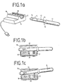
- FIG. 1 a shows a first exemplary embodiment of an indirectly heated curling iron 10 with a separate heating station 11.
- the curling iron 10 is composed in a known manner from a winding mandrel 12 and a handle part 13.
- a protective cap 14 is attached to the head part of the winding dome 12 and is made of a material with low thermal conductivity and thus does not heat up significantly.
- the winding mandrel 12 is made of heat-storing material and is wholly or partly interspersed with a magnetic material which changes its magnetic properties depending on the temperature (e.g. Thermoflux).
- the winding mandrel 12 has a ring 15 made of such a magnetic material in its central region. Of course, several such rings 15 can also be arranged on the winding dome 12.
- the at least one ring 15 is preferably arranged in the region of the two ends of the winding dome 12.
- the heating station 11 consists of a housing 16 which has a recess for introducing the winding mandrel 12.
- a heating block 18 shown schematically in FIG. 1 b, c, with a shape 17, which is heated by means of a resistance heater with a thermostat, a heater with a PTC resistor or the like.
- the invention is not limited to mains powered, i.e. electrical heating stations limited, but also applicable for, for example, gas-heated heating stations.
- Accidental touching of the heating block 18 can be avoided by a pivotable grid 19 covering the recess of the housing 16 and the shape 17 or similar protective measures.
- At least one permanent magnet 20 and one spring element 21 are embedded in the heating block 18.
- the permanent magnet 20 is positioned in the heating block in such a way that it coincides with the ring 15 attached to the winding mandrel 12 of the curling iron 10 as soon as the winding mandrel 12 has been properly inserted into the formation 17 of the heating station 11.
- the ring 15 has normal magnetic properties, so that with a suitable arrangement of the poles of the ring 15 and the permanent magnet 20 an attractive force occurs between the winding mandrel 12 and the heating block 18. This magnetic force outweighs that, essentially in the opposite direction, i.e.
- the winding mandrel 12 due to the predominant magnetic attraction in intimate thermal contact with the Schubbck 18 of the heating station 11, preferably at heating temperatures in the range between 200 ° C and 500 ° C, especially at about 250 ° C - 350 ° C is operated.
- the curling iron 10 rapidly heats up.
- the temperature of the heating block 18 changes only insignificantly during the heating process, since the heating output of the heating block 18 can be adapted to the respective requirements by means of a temperature control.
- the magnetic properties of the material of the ring 15 determine the desired temperature value of the winding dome 12 of the curling iron 10.
- the permeability of the ring material decreases. This leads to a reduction in the magnetic holding forces between the winding mandrel 12 and the heating block 18, so that finally the influence of the repulsive spring force of the spring element 21 takes over and the winding mandrel 12 from the heating block 18th takes off at the end of the heating process.
- the curling iron 10 is now ready for use and can be used for a longer period of time for hair styling.
- the temperature setpoint of the winding mandrel 12 is determined by a suitable selection of the ring material, preferably in the range between 100 ° C. and 200 ° C., in particular approximately 150 ° C., while the temperature of the heating block 18 is in particular approximately 100 ° C.-200 ° C is set higher. This measure ensures that the curling iron 10 heats up very quickly.
- the curling iron 10 has a very simple structure, can be cleaned quickly and easily and, due to the lack of electrically or mechanically sensitive components, has a very high level of operational reliability.
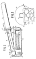
- FIG. Shown is the front view of the heating station 11, in which the winding mandrel 12 is inserted for heating.
- the heating block 18 is arranged in the upper region of the housing 16 of the heating station 11.
- the winding mandrel 12 of the curling iron 10 is inserted in the corresponding shape 17 of the heating block 18 hanging.
- the holding forces are applied by the magnetic effect between the at least one permanent magnet 20 in the heating block 18 and the magnetic material introduced into the winding mandrel 12.
- the force component acting essentially opposite to these magnetic forces results from the gravitational force.
- the curling iron 10 simply falls down from the heating block 18 after reaching the temperature setpoint value onto a bearing 22 preferably made of heat-resistant and heat-insulating material.
- a bearing 22 preferably made of heat-resistant and heat-insulating material.
- which in the present exemplary embodiment has a shape 23 for receiving the winding mandrel 12 of the curling iron 10.
- any spring elements for lifting the winding dome 12 from the heating block 18 can be dispensed with. However, care must be taken to ensure that the heating station 11 cannot be operated in an improper position.
- Improper positioning is particularly the case when the heating station 11 is set up in the side or head position, since then the force components of the releasing or attracting forces are aligned either parallel or perpendicular to one another and, in extreme cases, the winding mandrel 12 cannot be lifted off the heating block 18 .
- Such incorrect handling can be excluded by a suitable design of the housing 16 of the heating station 11.
- FIG. 2 shows some examples of this, namely attaching a handle 24 to the top or a strip 25 to the side parts of the housing 16.
- a partially cylindrical shape for the upper part of the housing 16 would also be conceivable, as shown by the dashed line Line 26 indicated. If you also ensure that the center of gravity of the heating station 11 with an inserted curling iron 10 comes to lie between the central axis of the partial cylinder and a base plate 27 of the housing 16, an incorrect installation of the housing 16 is made impossible because of the unstable position.
- FIG 3 another embodiment of the curling iron according to the invention is shown in detail.
- the heating station 11 is shown in longitudinal section with the winding mandrel 12 inserted but lifted off.
- the curling iron 10, which in the present example has an curling scissor blade 28, is mounted with its protective cap 14 in a shoulder 29 integrally formed in the interior of the housing 16 such that it can be pivoted or pivoted.
- a rod 30 is provided above the shoulder 29, which covers the protective cap 14 of the inserted curling iron 10.
- A approximately in the edges of a Aufschikkeidorn 12 comprising half-shell reshaped spring element 21, which is fixed in the area of the cap 14 of the inserted curling iron 10 on the heating station 11 and includes the winding mandrel 12 in the transition area to the handle 13 over about half the circumference, produces force component detaching the winding mandrel 12 from the heating block 18.
- the height of the shoulder 29 is fixed relative to the shape 17 of the heating block 18 in such a way that the winding dome 12 does not have any direct thermal contact with the heating block 18 at any point over its entire length in the raised state.
- the magnetic force is generated by means of a ring 15 arranged in the area of the winding mandrel 12 close to the handle or a different introduction of the magnetic material and the magnet 20 arranged in the heating block 18.
- the magnet 20 is slightly recessed in the shape 17 of the heating block 18, so that between the ring 15 of the winding mandrel 12 and the magnet 20 there is also a distance indicated by arrows 31 when the curling iron 10 for heating in the formation 17 is attached.
- This measure allows the ring 15 to be directly heated via the heating block 18 and the magnet 20 acting as a thermal bridge without a substantial reduction in the magnetic force effect. This ensures that the ring temperature is essentially determined by the temperature of the winding mandrel 12 and not by the tem temperature of the heating block 18 is determined.
- a good thermal contact between the winding mandrel 12 and the heating block 31 is to be ensured by means of the rod 30 above the shoulder 29.
- the rod 30 is therefore arranged at such a height with respect to the protective cap 14 of the inserted curling iron 10 that it is not possible to lift off the front part of the winding mandrel 12 during the heating phase.
- the lifting height of the winding mandrel 12 determined by the spring constant of the spring element 21 after the end of the heating process is determined in a very advantageous manner in such a way that the heat balance of the winding mandrel is balanced in the raised state.
- a constant temperature of the winding mandrel 12 is ensured even if it is in the heating station 11 in the raised state for a longer time.
- the height to be set individually depends on the individual case and must be determined individually by the responsible specialist.
- winding mandrel 12 from metal, preferably aluminum.
- the formation of the winding mandrel 12 as a latent heat store using storage materials such as wax, saline solution or the like can also be useful for extending the period of use of the curling iron 10.
- the invention can be further developed so that, for example, the heat of combustion is used for the catalytic combustion of a gaseous fuel for heating.
- a further, very advantageous embodiment of the invention provides for the attachment of at least two ferromagnetic bodies with different Curie temperatures to the winding mandrel 12 of the curling iron 10.
- a user-selectable immersion depth of the winding mandrel 12 in the heating block 18 there is the possibility of having at least one of the ferromagnetic bodies of different Curie temperatures come to coincide with the permanent magnet 20.
- This enables a setpoint temperature of the winding mandrel 12 which can be selected within wide limits, so that this temperature can be individually adapted to the user's hair condition.
Abstract
Claims (12)
Applications Claiming Priority (2)
| Application Number | Priority Date | Filing Date | Title |
|---|---|---|---|
| DE3538545 | 1985-10-30 | ||
| DE19853538545 DE3538545A1 (de) | 1985-10-30 | 1985-10-30 | Kabelloser lockenstab mit einer separaten heizstation |
Publications (2)
| Publication Number | Publication Date |
|---|---|
| EP0243386A1 EP0243386A1 (fr) | 1987-11-04 |
| EP0243386B1 true EP0243386B1 (fr) | 1990-02-28 |
Family
ID=6284788
Family Applications (1)
| Application Number | Title | Priority Date | Filing Date |
|---|---|---|---|
| EP86905729A Expired - Lifetime EP0243386B1 (fr) | 1985-10-30 | 1986-09-26 | Bigoudi sans fil avec unite de chauffage separe |
Country Status (4)
| Country | Link |
|---|---|
| US (1) | US4803341A (fr) |
| EP (1) | EP0243386B1 (fr) |
| DE (2) | DE3538545A1 (fr) |
| WO (1) | WO1987002555A1 (fr) |
Cited By (1)
| Publication number | Priority date | Publication date | Assignee | Title |
|---|---|---|---|---|
| DE19504199A1 (de) * | 1995-02-09 | 1996-05-15 | Rudolf Bauer | Scherenheizgerät |
Families Citing this family (36)
| Publication number | Priority date | Publication date | Assignee | Title |
|---|---|---|---|---|
| US5149942A (en) * | 1990-08-09 | 1992-09-22 | Garrett James A | Hot mirror to prevent condensation in humid environments |
| US5798500A (en) * | 1993-08-10 | 1998-08-25 | Stillwagon, Jr.; Ross I. | Curling iron stove with internal cavity with electric heater positioned therebelow |
| USD385705S (en) * | 1995-10-23 | 1997-11-04 | Braun Aktiengesellschaft | Cover for a curling brush |
| US5749379A (en) * | 1996-04-25 | 1998-05-12 | Golden Supreme, Inc. | Non-numeric temperature indicating method for a hair styling iron |
| US5713379A (en) * | 1996-09-25 | 1998-02-03 | Collins; Joyce E. | Curling iron system with a friction element to generate heat |
| US5785064A (en) * | 1997-03-07 | 1998-07-28 | Simpson; Timothy A. | High temperature externally heated hair-styling devices |
| US6758824B1 (en) * | 2000-11-06 | 2004-07-06 | Suros Surgical Systems, Inc. | Biopsy apparatus |
| US7458940B2 (en) | 2000-11-06 | 2008-12-02 | Suros Surgical Systems, Inc. | Biopsy apparatus |
| GB2376633B (en) * | 2000-11-06 | 2004-11-10 | Suros Surgical Systems Inc | Biopsy apparatus |
| US7009519B2 (en) * | 2002-11-21 | 2006-03-07 | S.C. Johnson & Sons, Inc. | Product dispensing controlled by RFID tags |
| US6968961B1 (en) | 2003-02-07 | 2005-11-29 | Elizabeth Peete | Organizer for tools |
| EP1639862B1 (fr) | 2003-06-27 | 2007-08-15 | S.C. Johnson & Son, Inc. | Ensembles distributeurs et systemes comprenant une unite de stockage de la chaleur |
| US7208707B2 (en) * | 2003-06-27 | 2007-04-24 | S.C. Johnson & Son, Inc. | Dispenser assemblies and systems including a heat storage unit |
| EP1673015B1 (fr) * | 2003-10-14 | 2014-03-19 | Suros Surgical Systems, Inc. | Ensemble d'aiguilles de biopsie par aspiration |
| US7988642B2 (en) * | 2003-10-14 | 2011-08-02 | Suros Surgical Systems, Inc. | Vacuum assisted biopsy device |
| US8048003B2 (en) | 2003-10-14 | 2011-11-01 | Suros Surgical Systems, Inc. | Vacuum assisted biopsy device |
| US6996916B2 (en) * | 2004-03-09 | 2006-02-14 | Helen Of Troy Limited | Variable ion hair styling appliances |
| US20050224091A1 (en) * | 2004-04-08 | 2005-10-13 | Helen Of Troy Limited | Ion curling iron and straightener |
| US9638770B2 (en) | 2004-05-21 | 2017-05-02 | Devicor Medical Products, Inc. | MRI biopsy apparatus incorporating an imageable penetrating portion |
| US8932233B2 (en) | 2004-05-21 | 2015-01-13 | Devicor Medical Products, Inc. | MRI biopsy device |
| US7708751B2 (en) | 2004-05-21 | 2010-05-04 | Ethicon Endo-Surgery, Inc. | MRI biopsy device |
| US20050284856A1 (en) * | 2004-06-17 | 2005-12-29 | Helen Of Troy Limited | Rechargeable hair styling appliances and charging stand |
| US7556622B2 (en) * | 2005-05-18 | 2009-07-07 | Suros Surgical Systems, Inc. | Selectively openable tissue filter |
| US8202229B2 (en) * | 2007-10-01 | 2012-06-19 | Suros Surgical Systems, Inc. | Surgical device |
| US8808200B2 (en) | 2007-10-01 | 2014-08-19 | Suros Surgical Systems, Inc. | Surgical device and method of using same |
| US8529468B2 (en) | 2009-07-01 | 2013-09-10 | Suros Surgical Systems, Inc. | Surgical system |
| USD669083S1 (en) * | 2010-11-16 | 2012-10-16 | Tru-Test Limited | Wireless tag reader |
| AT13546U1 (de) * | 2013-03-08 | 2014-03-15 | A Tron3D Gmbh | Halterung für einen Intraoralscanner |
| US9474347B2 (en) | 2014-02-11 | 2016-10-25 | Christopher Lee Pedroarena | Cordless hairstyling tools with rechargeable and interchangeable batteries |
| US20160007707A1 (en) * | 2014-07-09 | 2016-01-14 | Tojuana Carter | Hair Styling Tool and Heating System |
| SG10201405855YA (en) * | 2014-09-18 | 2016-04-28 | Tai Wah Distributors Private Ltd | Hair styling appliances heating device |
| USD864480S1 (en) | 2016-07-07 | 2019-10-22 | Calor | Water tank for hair straightening apparatus |
| CA171933S (en) | 2016-07-07 | 2017-08-30 | Calor (Société Par Actions Simplifiée) | Hair straightening apparatus |
| USD859740S1 (en) | 2016-07-07 | 2019-09-10 | Calor | Hair straightening apparatus with removable component |
| CA171932S (en) | 2016-07-07 | 2017-08-30 | Calor (Société Par Actions Simplifiée) | Hair straightening apparatus |
| USD872360S1 (en) * | 2018-02-28 | 2020-01-07 | Lunata Inc. | Cordless curling iron |
Family Cites Families (14)
| Publication number | Priority date | Publication date | Assignee | Title |
|---|---|---|---|---|
| US1917305A (en) * | 1932-03-21 | 1933-07-11 | Anthon G Johnson | Oil heater for permanent hair waving equipment |
| US2584999A (en) * | 1947-01-24 | 1952-02-12 | Margaret Thurston Flournoy | Curling iron |
| DE1677223U (de) * | 1953-11-21 | 1954-06-03 | Georg Weis | Automatischer ondulierscherenerhitzer. |
| FR1318727A (fr) * | 1962-01-10 | 1963-02-22 | Chauffe-fer électrique automatique à l'usage de la coiffure | |
| GB1082555A (en) * | 1965-07-05 | 1967-09-06 | George E Taylor & Company Ltd | Improvements in or relating to hair curlers |
| AT308994B (de) * | 1968-06-06 | 1973-07-25 | Accessair Sa | Lockenwickler |
| US3594543A (en) * | 1969-08-11 | 1971-07-20 | Scovill Manufacturing Co | Hair-setting device |
| US3654428A (en) * | 1970-05-25 | 1972-04-04 | Songrand Corp The | Apparatus for heating and conditioning hair curling rollers |
| US3881086A (en) * | 1973-08-20 | 1975-04-29 | Clairol Inc | Heatable hair roller and heating unit for use therewith |
| US3946196A (en) * | 1974-06-13 | 1976-03-23 | Schick Incorporated | Hair curling appliance |
| US4109667A (en) * | 1976-11-08 | 1978-08-29 | Stackpole Carbon Company | Hair setting roller |
| DE3137545A1 (de) * | 1981-09-22 | 1983-05-05 | Waltraud 8520 Erlangen Turbanisch | Uni - look - s lockenstab |
| US4499355A (en) * | 1982-09-30 | 1985-02-12 | Clairol Incorporated | Heated personal care appliances |
| DE3434072A1 (de) * | 1984-09-17 | 1986-03-27 | Braun Ag, 6000 Frankfurt | Haarbehandlungseinrichtung |
-
1985
- 1985-10-30 DE DE19853538545 patent/DE3538545A1/de not_active Withdrawn
-
1986
- 1986-09-26 US US07/071,280 patent/US4803341A/en not_active Expired - Fee Related
- 1986-09-26 EP EP86905729A patent/EP0243386B1/fr not_active Expired - Lifetime
- 1986-09-26 DE DE8686905729T patent/DE3669096D1/de not_active Expired - Fee Related
- 1986-09-26 WO PCT/DE1986/000397 patent/WO1987002555A1/fr active IP Right Grant
Cited By (1)
| Publication number | Priority date | Publication date | Assignee | Title |
|---|---|---|---|---|
| DE19504199A1 (de) * | 1995-02-09 | 1996-05-15 | Rudolf Bauer | Scherenheizgerät |
Also Published As
| Publication number | Publication date |
|---|---|
| WO1987002555A1 (fr) | 1987-05-07 |
| DE3669096D1 (de) | 1990-04-05 |
| EP0243386A1 (fr) | 1987-11-04 |
| US4803341A (en) | 1989-02-07 |
| DE3538545A1 (de) | 1987-05-07 |
Similar Documents
| Publication | Publication Date | Title |
|---|---|---|
| EP0243386B1 (fr) | Bigoudi sans fil avec unite de chauffage separe | |
| DE3205658A1 (de) | Elektroherd mit temperaturwarneinrichtung | |
| DE2549284A1 (de) | Elektrische brennschere | |
| EP0318895A2 (fr) | Elément chauffant tubulaire | |
| DE575523C (de) | Heizbarer Rasierapparat | |
| DE3620910C2 (fr) | ||
| EP0927428B1 (fr) | Element chauffant a rayonnement pour une zone de cuisson | |
| DE2628597C3 (de) | Verriegelungsvorrichtung für Türen u.dgl. an elektrisch betriebenen Geräten | |
| DE3443306C1 (de) | Elektrischer Patronenheizkoerper | |
| EP0175232B1 (fr) | Dispositif pour le traitement des cheveux | |
| DE2900677C2 (de) | Zigarrenanzünder | |
| DE3005441C2 (fr) | ||
| DE3204119A1 (de) | Elektroherd mit temperaturwarneinrichtung | |
| DE3241173C2 (de) | Zigarrenanzünder | |
| DE19941901A1 (de) | Rohrheizkörper mit NTC/PTC-Absicherung | |
| EP0162940B1 (fr) | Interrupteur de protection contre les surchages | |
| DE2436434B2 (de) | Ueberhitzungsschutz fuer elektrische zigarrenanzuender | |
| DE2462344C3 (de) | Dampffrisierstab | |
| DE4104212C2 (fr) | ||
| DE3037549C2 (fr) | ||
| DE2205353C2 (de) | Heizflansch für einen elektrischen Wasserkocher | |
| DE2041063A1 (de) | Elektrische Schmelzsicherung | |
| AT148386B (de) | Haardauerwellgerät. | |
| EP1041596B1 (fr) | Dispositif de déclenchement thermique pour disjoncteur | |
| DE1193577B (de) | Durch Strombeheizung und Volumenaenderung betaetigbare Steuervorrichtung, z. B. fuer elektrische Schalter |
Legal Events
| Date | Code | Title | Description |
|---|---|---|---|
| PUAI | Public reference made under article 153(3) epc to a published international application that has entered the european phase |
Free format text: ORIGINAL CODE: 0009012 |
|
| 17P | Request for examination filed |
Effective date: 19870613 |
|
| AK | Designated contracting states |
Kind code of ref document: A1 Designated state(s): CH DE FR GB IT LI NL SE |
|
| 17Q | First examination report despatched |
Effective date: 19890104 |
|
| ITF | It: translation for a ep patent filed |
Owner name: DE DOMINICIS & MAYER S.R.L. |
|
| GRAA | (expected) grant |
Free format text: ORIGINAL CODE: 0009210 |
|
| AK | Designated contracting states |
Kind code of ref document: B1 Designated state(s): CH DE FR GB IT LI NL SE |
|
| ET | Fr: translation filed | ||
| REF | Corresponds to: |
Ref document number: 3669096 Country of ref document: DE Date of ref document: 19900405 |
|
| GBT | Gb: translation of ep patent filed (gb section 77(6)(a)/1977) | ||
| PGFP | Annual fee paid to national office [announced via postgrant information from national office to epo] |
Ref country code: DE Payment date: 19900810 Year of fee payment: 5 |
|
| PGFP | Annual fee paid to national office [announced via postgrant information from national office to epo] |
Ref country code: GB Payment date: 19900820 Year of fee payment: 5 |
|
| PGFP | Annual fee paid to national office [announced via postgrant information from national office to epo] |
Ref country code: FR Payment date: 19900906 Year of fee payment: 5 |
|
| PG25 | Lapsed in a contracting state [announced via postgrant information from national office to epo] |
Ref country code: SE Effective date: 19900927 |
|
| ITTA | It: last paid annual fee | ||
| PGFP | Annual fee paid to national office [announced via postgrant information from national office to epo] |
Ref country code: CH Payment date: 19901004 Year of fee payment: 5 |
|
| PLBE | No opposition filed within time limit |
Free format text: ORIGINAL CODE: 0009261 |
|
| STAA | Information on the status of an ep patent application or granted ep patent |
Free format text: STATUS: NO OPPOSITION FILED WITHIN TIME LIMIT |
|
| 26N | No opposition filed | ||
| PG25 | Lapsed in a contracting state [announced via postgrant information from national office to epo] |
Ref country code: NL Effective date: 19910401 |
|
| NLV4 | Nl: lapsed or anulled due to non-payment of the annual fee | ||
| PG25 | Lapsed in a contracting state [announced via postgrant information from national office to epo] |
Ref country code: GB Effective date: 19910926 |
|
| PG25 | Lapsed in a contracting state [announced via postgrant information from national office to epo] |
Ref country code: LI Effective date: 19910930 Ref country code: CH Effective date: 19910930 |
|
| GBPC | Gb: european patent ceased through non-payment of renewal fee | ||
| PG25 | Lapsed in a contracting state [announced via postgrant information from national office to epo] |
Ref country code: FR Effective date: 19920529 |
|
| REG | Reference to a national code |
Ref country code: CH Ref legal event code: PL |
|
| PG25 | Lapsed in a contracting state [announced via postgrant information from national office to epo] |
Ref country code: DE Effective date: 19920602 |
|
| REG | Reference to a national code |
Ref country code: FR Ref legal event code: ST |
|
| EUG | Se: european patent has lapsed |
Ref document number: 86905729.9 Effective date: 19910527 |
|
| PG25 | Lapsed in a contracting state [announced via postgrant information from national office to epo] |
Ref country code: IT Free format text: LAPSE BECAUSE OF NON-PAYMENT OF DUE FEES;WARNING: LAPSES OF ITALIAN PATENTS WITH EFFECTIVE DATE BEFORE 2007 MAY HAVE OCCURRED AT ANY TIME BEFORE 2007. THE CORRECT EFFECTIVE DATE MAY BE DIFFERENT FROM THE ONE RECORDED. Effective date: 20050926 |