EP0243301A1 - Appareil pour la descente de personnes - Google Patents
Appareil pour la descente de personnes Download PDFInfo
- Publication number
- EP0243301A1 EP0243301A1 EP87810157A EP87810157A EP0243301A1 EP 0243301 A1 EP0243301 A1 EP 0243301A1 EP 87810157 A EP87810157 A EP 87810157A EP 87810157 A EP87810157 A EP 87810157A EP 0243301 A1 EP0243301 A1 EP 0243301A1
- Authority
- EP
- European Patent Office
- Prior art keywords
- brake
- lever
- spring
- person
- load
- Prior art date
- Legal status (The legal status is an assumption and is not a legal conclusion. Google has not performed a legal analysis and makes no representation as to the accuracy of the status listed.)
- Granted
Links
- 230000006835 compression Effects 0.000 claims description 9
- 238000007906 compression Methods 0.000 claims description 9
- 230000036316 preload Effects 0.000 claims description 3
- 230000037396 body weight Effects 0.000 description 5
- 229910000831 Steel Inorganic materials 0.000 description 1
- 230000008878 coupling Effects 0.000 description 1
- 238000010168 coupling process Methods 0.000 description 1
- 238000005859 coupling reaction Methods 0.000 description 1
- 230000003111 delayed effect Effects 0.000 description 1
- 230000000694 effects Effects 0.000 description 1
- 239000010959 steel Substances 0.000 description 1
Images

Classifications
-
- A—HUMAN NECESSITIES
- A62—LIFE-SAVING; FIRE-FIGHTING
- A62B—DEVICES, APPARATUS OR METHODS FOR LIFE-SAVING
- A62B1/00—Devices for lowering persons from buildings or the like
- A62B1/06—Devices for lowering persons from buildings or the like by making use of rope-lowering devices
- A62B1/08—Devices for lowering persons from buildings or the like by making use of rope-lowering devices with brake mechanisms for the winches or pulleys
- A62B1/10—Devices for lowering persons from buildings or the like by making use of rope-lowering devices with brake mechanisms for the winches or pulleys mechanically operated
Definitions
- the invention relates to a personal descender, consisting of a rope, one end of which has fastening means for fixed attachment to a part of the building and the other end of which is attached to a rope drum which is rotatably mounted in a frame, the frame has connecting devices for a person carrying device, the cable drum is operatively connected to a brake which serves to regulate the abseiling speed and is under spring preload, the brake being operable during abseiling via a brake lever designed as a rocker and the brake lever on the one hand for manually releasing the brake via a first actuating element against the prestressing spring force and on the other hand for manually increasing the braking force can be influenced by a second actuator.
- a person descender of this type, from which the invention is based, is known from DE-PS 26 46 368.
- This known abseiling device ensures a constant abseiling speed without having to actuate the brake acting on the rope drum, but only if the brake acting on the rope drum has previously been adjusted to the body weight of the person to be abseiled.
- the object of the invention is now to provide a person descender of the type specified in the preamble of claim 1 while maintaining the same in the prior art enough advantages, which consist in the fact that the abseiling speed can be both delayed and increased to a standstill by the person to be abseiled during abseiling, if necessary, in such a way that a constant abseiling speed can otherwise be achieved with simple means and measures without the brake have to adjust beforehand to the respective body weight of the person to be abseiled.
- the solution to this problem is characterized in that the brake lever is connected to the person-carrying device via a spring held on the frame and the spring is arranged so that it can be pre-tensioned by the load acting on the person-carrying device in such a way that the spring engages the braking force at a low load to reduce the braking force , at high load, however, in a position increasing the braking force.
- a technically particularly advantageous embodiment of the above-described device is characterized in that the compression spring is arranged coaxially in its direction of action to the direction of the load acting on the person carrying device, is supported with one end on the frame, and is also penetrated by a traction element, which with its a first end at the other end engages the compression spring, and that the other second end of the tension member are connected to the person-carrying device and the first end of the tension member is connected to the brake lever.
- the aforementioned pulling element is connected to the brake lever via a lever pivotably articulated on the frame.
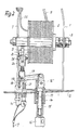
- a cable drum 2 is rotatably mounted about a frame-fixed axis 3 on an annularly closed frame 1.
- the cable drum 2 is provided on its end face with a cylindrical recess 22 in which two brake shoes acting on the cylindrical outside thereof are arranged in a known manner.
- the two brake shoes are pivotally connected about the pivot points 23 and 24 to a supporting part 25 which is fixedly connected to the frame 1.
- the support part 25 is provided with a shoulder 26 in which a brake shoe actuation shaft rigidly connected to the brake lever 5 is rotatably mounted.
- the latter is flattened on its side protruding from the extension 26, located between the two free ends of the brake shoes, so that when the brake lever 5 is pivoted, a corresponding actuation of the flattened part of the actuating shaft 5, which acts as a brake shoe spreading part, rests on its free ends Brake shoes is effected.
- a spring 1 which is held on the frame 1 and which is adjustable in its spring force engages Tension spring 7 on.
- a tension member 9 in the form of a steel cable with which the brake 4 can be released manually against the spring force of the tension spring 7.
- the lever arm 8 of the brake lever 5 is also connected to a second pulling element 10 in the form of a manually operable Bowden cable, with which the braking force of the shoe brake 4 can be braked manually until the cable drum 2 comes to a standstill, for which purpose the brake lever 5 is pivoted clockwise.
- the wire rope 11 fixed to the rope drum 2 with one end is guided in a known manner through the upper end part of the frame 1, and has at its free end, e.g. a snap hook, to fix the free end of the rope in a suitable part of the building.
- a person carrying device is attached at the lower end of the frame 1. Furthermore, the abseiling device is surrounded by a housing 12.
- a sleeve 13 is fastened, in which a spring 14 designed as a helical compression spring is inserted so that its direction of action is perpendicular.
- the lower end part of the spring is supported on the bottom of the sleeve 13.
- a pulling element 15 designed as a head pin engages, the head of which is supported indirectly on the upper end part of the spring 14.
- an eyelet 16 is screwed for connecting the person carrying device. By more or less screwing the eyelet 16 onto the shaft of the tension member 15, the spring preload of the spring 14 can be changed.
- the head of the pulling member 15 is gripped from the bottom of a fork piece 16 ', to which a one-armed lever 17 is articulated, the fulcrum 18 on the load arm of a two ten, two-armed and pivotally mounted on the frame 1 lever 19.
- the power arm of the lever 19 is connected to the tension member 9.
- the load arm of the lever 17 is articulated to the lever arm 8 of the brake lever 5 via a variable-length coupling piece 20.
- a return spring 21 is provided which is fixed to the frame and is effective on the tension member 9.
Landscapes
- Engineering & Computer Science (AREA)
- Mechanical Engineering (AREA)
- Health & Medical Sciences (AREA)
- General Health & Medical Sciences (AREA)
- Business, Economics & Management (AREA)
- Emergency Management (AREA)
- Braking Arrangements (AREA)
- Emergency Lowering Means (AREA)
- Finger-Pressure Massage (AREA)
- Invalid Beds And Related Equipment (AREA)
Priority Applications (1)
| Application Number | Priority Date | Filing Date | Title |
|---|---|---|---|
| AT87810157T ATE59306T1 (de) | 1986-03-22 | 1987-03-19 | Personen-abseilgeraet. |
Applications Claiming Priority (2)
| Application Number | Priority Date | Filing Date | Title |
|---|---|---|---|
| DE3609824 | 1986-03-22 | ||
| DE19863609824 DE3609824A1 (de) | 1986-03-22 | 1986-03-22 | Personen-abseilgeraet |
Publications (2)
| Publication Number | Publication Date |
|---|---|
| EP0243301A1 true EP0243301A1 (fr) | 1987-10-28 |
| EP0243301B1 EP0243301B1 (fr) | 1990-12-27 |
Family
ID=6297100
Family Applications (1)
| Application Number | Title | Priority Date | Filing Date |
|---|---|---|---|
| EP87810157A Expired - Lifetime EP0243301B1 (fr) | 1986-03-22 | 1987-03-19 | Appareil pour la descente de personnes |
Country Status (5)
| Country | Link |
|---|---|
| US (1) | US4730703A (fr) |
| EP (1) | EP0243301B1 (fr) |
| JP (1) | JPS62290476A (fr) |
| AT (1) | ATE59306T1 (fr) |
| DE (2) | DE3609824A1 (fr) |
Families Citing this family (8)
| Publication number | Priority date | Publication date | Assignee | Title |
|---|---|---|---|---|
| WO2005035063A1 (fr) * | 2003-10-10 | 2005-04-21 | Hyun Dal Lee | Dispositif de sauvetage |
| GB0410957D0 (en) * | 2004-05-15 | 2004-06-16 | Renton Julian E | Personal height rescue apparatus |
| KR100476536B1 (ko) * | 2004-07-03 | 2005-03-17 | (주)아이 에스 피 엘 | 인명 피난 장비 |
| US20060163000A1 (en) * | 2005-01-24 | 2006-07-27 | Roy Chowthi | Personal fire escape system |
| DE102005010767B4 (de) * | 2005-03-09 | 2007-01-11 | Mittelmann Sicherheitstechnik Gmbh & Co.Kg | Abseilgerät mit Windenfunktion |
| GB0910998D0 (en) * | 2009-06-24 | 2009-08-05 | Drop Zone Uk Ltd | Regulated descender |
| RU2414263C1 (ru) * | 2009-08-12 | 2011-03-20 | Валерий Васильевич Попов | Устройство экстренной эвакуации |
| EP2915770B1 (fr) * | 2014-03-03 | 2016-10-05 | Actsafe Systems AB | Interface utilisateur pour système motorisé portatif |
Citations (5)
| Publication number | Priority date | Publication date | Assignee | Title |
|---|---|---|---|---|
| DE79875C (fr) * | ||||
| DE2646368B1 (de) * | 1976-10-14 | 1978-04-27 | Hans Neuendorf | Abseilgeraet fuer beruflichen Gebrauch |
| DE2743052A1 (de) * | 1977-09-24 | 1979-04-05 | Manfred Wirth | Automatisches sicherheitsabseilgeraet |
| DE2903403A1 (de) * | 1979-01-30 | 1980-08-07 | Rudolf F Hermani | Personenabseilrettungsgeraet |
| EP0039075A2 (fr) * | 1980-04-25 | 1981-11-04 | Rudolf Hermani GmbH | Dispositif de descente à câble pour personnes, en particulier pour le sauvetage hors d'immeubles hauts |
Family Cites Families (8)
| Publication number | Priority date | Publication date | Assignee | Title |
|---|---|---|---|---|
| US28273A (en) * | 1860-05-15 | Machine fob hoisting peesons | ||
| US916823A (en) * | 1906-04-24 | 1909-03-30 | Henry P Young | Automatic fire-escape. |
| DE2035933C3 (de) * | 1970-07-20 | 1975-02-20 | Otto 8112 Bad-Kohlgrub Brda | Bergungsgerät für Personenseilbahnen, Sessellifte o.ä |
| DE2064761C3 (de) * | 1970-12-31 | 1974-04-18 | Otto 8112 Bad-Kohlgrub Brda | Abseilgerät mit Laufseil zum Abseilen von Personen oder Lasten |
| DE2231844C3 (de) * | 1972-06-29 | 1981-01-15 | Otto Brda | Abseilgerat |
| US3915432A (en) * | 1973-11-13 | 1975-10-28 | Carlos Roberto Bustamante | Triple action mechanical chute-hoist |
| AT384741B (de) * | 1979-07-31 | 1987-12-28 | Bloder Hans | Rettungsgeraet zum abseilen von personen |
| JPS61127753U (fr) * | 1985-01-28 | 1986-08-11 |
-
1986
- 1986-03-22 DE DE19863609824 patent/DE3609824A1/de not_active Withdrawn
-
1987
- 1987-03-13 US US07/025,610 patent/US4730703A/en not_active Expired - Fee Related
- 1987-03-19 AT AT87810157T patent/ATE59306T1/de not_active IP Right Cessation
- 1987-03-19 DE DE8787810157T patent/DE3767015D1/de not_active Expired - Lifetime
- 1987-03-19 EP EP87810157A patent/EP0243301B1/fr not_active Expired - Lifetime
- 1987-03-20 JP JP62064475A patent/JPS62290476A/ja active Pending
Patent Citations (5)
| Publication number | Priority date | Publication date | Assignee | Title |
|---|---|---|---|---|
| DE79875C (fr) * | ||||
| DE2646368B1 (de) * | 1976-10-14 | 1978-04-27 | Hans Neuendorf | Abseilgeraet fuer beruflichen Gebrauch |
| DE2743052A1 (de) * | 1977-09-24 | 1979-04-05 | Manfred Wirth | Automatisches sicherheitsabseilgeraet |
| DE2903403A1 (de) * | 1979-01-30 | 1980-08-07 | Rudolf F Hermani | Personenabseilrettungsgeraet |
| EP0039075A2 (fr) * | 1980-04-25 | 1981-11-04 | Rudolf Hermani GmbH | Dispositif de descente à câble pour personnes, en particulier pour le sauvetage hors d'immeubles hauts |
Also Published As
| Publication number | Publication date |
|---|---|
| DE3609824A1 (de) | 1987-09-24 |
| JPS62290476A (ja) | 1987-12-17 |
| ATE59306T1 (de) | 1991-01-15 |
| US4730703A (en) | 1988-03-15 |
| EP0243301B1 (fr) | 1990-12-27 |
| DE3767015D1 (de) | 1991-02-07 |
Similar Documents
| Publication | Publication Date | Title |
|---|---|---|
| DE29715225U1 (de) | Bremse für eine schiebbare Gehhilfe zur Rehabilitation | |
| DE7035640U (de) | Sicherheitsvorrichtung gegen sturz. | |
| DE19746294C2 (de) | Sicherheitsvorrichtung für Auf- und Abseilvorgänge | |
| EP0243301B1 (fr) | Appareil pour la descente de personnes | |
| DE2156899C2 (de) | Automatische Nachstellvorrichtung für eine Trommelbremse | |
| DE2841869A1 (de) | Fersenhalter fuer ausloeseskibindung | |
| EP0080060B1 (fr) | Talonnière pour fixation de ski | |
| DE1890527U (de) | Felgenbremse. | |
| DE2906726A1 (de) | Fersenstrammer fuer sicherheits-skibindungen | |
| DE2732202C2 (de) | Vorrichtung zum Heben und Senken von Lasten | |
| DE2802832A1 (de) | Abstiegs- und/oder rettungseinrichtung | |
| DE3726158A1 (de) | Verfahren und vorrichtung zur bergung von an bauten verunglueckten personen | |
| DE2049611A1 (de) | Fersenteil für eine Ski-Sicherheitsbindung | |
| DE2646368C2 (de) | Abseilgerät für beruflichen Gebrauch | |
| DE8326565U1 (de) | Hebevorrichtung | |
| DE1428868A1 (de) | Skisicherheitsbindung | |
| DE3606309C2 (fr) | ||
| DE2115403B2 (de) | Seilspannungsregler fuer steuerseile | |
| AT387496B (de) | Angelrolle | |
| DE828167C (de) | Grindelkopf mit UEberlastungsausloeser | |
| DE3938942C2 (fr) | ||
| DE886729C (de) | Kettenbaumbremse fuer Webstuehle | |
| AT243142B (de) | Sicherheitsvorrichtung zum Festhalten des hinteren Schuhteiles auf einem Ski | |
| DE710107C (de) | Bedienungseinrichtung fuer einen Bremshebel mit Feststellvorrichtung | |
| DE4435127C2 (de) | Anordnung zum Mindern oder Unterbrechen der Wirkung einer Rückstellkraft |
Legal Events
| Date | Code | Title | Description |
|---|---|---|---|
| PUAI | Public reference made under article 153(3) epc to a published international application that has entered the european phase |
Free format text: ORIGINAL CODE: 0009012 |
|
| AK | Designated contracting states |
Kind code of ref document: A1 Designated state(s): AT BE CH DE ES FR GB GR IT LI LU NL SE |
|
| 17P | Request for examination filed |
Effective date: 19880426 |
|
| 17Q | First examination report despatched |
Effective date: 19891109 |
|
| GRAA | (expected) grant |
Free format text: ORIGINAL CODE: 0009210 |
|
| AK | Designated contracting states |
Kind code of ref document: B1 Designated state(s): AT BE CH DE ES FR GB GR IT LI LU NL SE |
|
| PG25 | Lapsed in a contracting state [announced via postgrant information from national office to epo] |
Ref country code: IT Free format text: LAPSE BECAUSE OF FAILURE TO SUBMIT A TRANSLATION OF THE DESCRIPTION OR TO PAY THE FEE WITHIN THE PRE;WARNING: LAPSES OF ITALIAN PATENTS WITH EFFECTIVE DATE BEFORE 2007 MAY HAVE OCCURRED AT ANY TIME BEFORE 2007. THE CORRECT EFFECTIVE DATE MAY BE DIFFERENT FROM THE ONE RECORDED.SCRIBED TIME-LIMIT Effective date: 19901227 Ref country code: GB Effective date: 19901227 Ref country code: GR Free format text: LAPSE BECAUSE OF FAILURE TO SUBMIT A TRANSLATION OF THE DESCRIPTION OR TO PAY THE FEE WITHIN THE PRESCRIBED TIME-LIMIT Effective date: 19901227 Ref country code: NL Effective date: 19901227 Ref country code: SE Free format text: THE PATENT HAS BEEN ANNULLED BY A DECISION OF A NATIONAL AUTHORITY Effective date: 19901227 Ref country code: BE Effective date: 19901227 Ref country code: FR Effective date: 19901227 |
|
| REF | Corresponds to: |
Ref document number: 59306 Country of ref document: AT Date of ref document: 19910115 Kind code of ref document: T |
|
| REF | Corresponds to: |
Ref document number: 3767015 Country of ref document: DE Date of ref document: 19910207 |
|
| PGFP | Annual fee paid to national office [announced via postgrant information from national office to epo] |
Ref country code: CH Payment date: 19910222 Year of fee payment: 5 |
|
| PG25 | Lapsed in a contracting state [announced via postgrant information from national office to epo] |
Ref country code: AT Effective date: 19910319 |
|
| PG25 | Lapsed in a contracting state [announced via postgrant information from national office to epo] |
Ref country code: LU Free format text: LAPSE BECAUSE OF NON-PAYMENT OF DUE FEES Effective date: 19910331 |
|
| PG25 | Lapsed in a contracting state [announced via postgrant information from national office to epo] |
Ref country code: ES Free format text: LAPSE BECAUSE OF FAILURE TO SUBMIT A TRANSLATION OF THE DESCRIPTION OR TO PAY THE FEE WITHIN THE PRESCRIBED TIME-LIMIT Effective date: 19910407 |
|
| NLV1 | Nl: lapsed or annulled due to failure to fulfill the requirements of art. 29p and 29m of the patents act | ||
| EN | Fr: translation not filed | ||
| GBV | Gb: ep patent (uk) treated as always having been void in accordance with gb section 77(7)/1977 [no translation filed] | ||
| PLBE | No opposition filed within time limit |
Free format text: ORIGINAL CODE: 0009261 |
|
| STAA | Information on the status of an ep patent application or granted ep patent |
Free format text: STATUS: NO OPPOSITION FILED WITHIN TIME LIMIT |
|
| 26N | No opposition filed | ||
| PG25 | Lapsed in a contracting state [announced via postgrant information from national office to epo] |
Ref country code: DE Effective date: 19920101 |
|
| PG25 | Lapsed in a contracting state [announced via postgrant information from national office to epo] |
Ref country code: LI Effective date: 19920331 Ref country code: CH Effective date: 19920331 |
|
| REG | Reference to a national code |
Ref country code: CH Ref legal event code: PL |