EP0239104A2 - Dispositif de coupe pour déchiqueteur de documents - Google Patents
Dispositif de coupe pour déchiqueteur de documents Download PDFInfo
- Publication number
- EP0239104A2 EP0239104A2 EP87104455A EP87104455A EP0239104A2 EP 0239104 A2 EP0239104 A2 EP 0239104A2 EP 87104455 A EP87104455 A EP 87104455A EP 87104455 A EP87104455 A EP 87104455A EP 0239104 A2 EP0239104 A2 EP 0239104A2
- Authority
- EP
- European Patent Office
- Prior art keywords
- cutting
- scraper
- cutting device
- strips
- plates
- Prior art date
- Legal status (The legal status is an assumption and is not a legal conclusion. Google has not performed a legal analysis and makes no representation as to the accuracy of the status listed.)
- Granted
Links
- 238000005520 cutting process Methods 0.000 title claims abstract description 40
- 210000001331 nose Anatomy 0.000 description 9
- 239000002245 particle Substances 0.000 description 6
- 239000000463 material Substances 0.000 description 4
- 238000010276 construction Methods 0.000 description 1
- 238000000926 separation method Methods 0.000 description 1
Images

Classifications
-
- B—PERFORMING OPERATIONS; TRANSPORTING
- B02—CRUSHING, PULVERISING, OR DISINTEGRATING; PREPARATORY TREATMENT OF GRAIN FOR MILLING
- B02C—CRUSHING, PULVERISING, OR DISINTEGRATING IN GENERAL; MILLING GRAIN
- B02C18/00—Disintegrating by knives or other cutting or tearing members which chop material into fragments
- B02C18/0007—Disintegrating by knives or other cutting or tearing members which chop material into fragments specially adapted for disintegrating documents
-
- B—PERFORMING OPERATIONS; TRANSPORTING
- B02—CRUSHING, PULVERISING, OR DISINTEGRATING; PREPARATORY TREATMENT OF GRAIN FOR MILLING
- B02C—CRUSHING, PULVERISING, OR DISINTEGRATING IN GENERAL; MILLING GRAIN
- B02C18/00—Disintegrating by knives or other cutting or tearing members which chop material into fragments
- B02C18/06—Disintegrating by knives or other cutting or tearing members which chop material into fragments with rotating knives
- B02C18/14—Disintegrating by knives or other cutting or tearing members which chop material into fragments with rotating knives within horizontal containers
- B02C18/142—Disintegrating by knives or other cutting or tearing members which chop material into fragments with rotating knives within horizontal containers with two or more inter-engaging rotatable cutter assemblies
-
- B—PERFORMING OPERATIONS; TRANSPORTING
- B02—CRUSHING, PULVERISING, OR DISINTEGRATING; PREPARATORY TREATMENT OF GRAIN FOR MILLING
- B02C—CRUSHING, PULVERISING, OR DISINTEGRATING IN GENERAL; MILLING GRAIN
- B02C18/00—Disintegrating by knives or other cutting or tearing members which chop material into fragments
- B02C18/06—Disintegrating by knives or other cutting or tearing members which chop material into fragments with rotating knives
- B02C18/16—Details
- B02C18/18—Knives; Mountings thereof
- B02C18/182—Disc-shaped knives
-
- B—PERFORMING OPERATIONS; TRANSPORTING
- B02—CRUSHING, PULVERISING, OR DISINTEGRATING; PREPARATORY TREATMENT OF GRAIN FOR MILLING
- B02C—CRUSHING, PULVERISING, OR DISINTEGRATING IN GENERAL; MILLING GRAIN
- B02C18/00—Disintegrating by knives or other cutting or tearing members which chop material into fragments
- B02C18/0007—Disintegrating by knives or other cutting or tearing members which chop material into fragments specially adapted for disintegrating documents
- B02C2018/0069—Disintegrating by knives or other cutting or tearing members which chop material into fragments specially adapted for disintegrating documents with stripping devices
Definitions
- the invention relates to a cutting device for document shredders according to the preamble of the main claim, especially to so-called particle cutters with a longitudinal cut and additional cross separation of the material.
- DE-PS 27 49 482 already discloses a scraper system for the shaft bottom and cutting roller surface which is specifically intended for document shredders of the type in question, which consists of strippers which are arranged next to one another and fully encompass the roller base and additionally comprise auxiliary strippers which lie on the roller surface in a sector-like manner common bearing rods are lined up and held in this way in the housing, but this is precisely a construction that offers the fine and thus unstable cutting particles a wealth of possibilities to penetrate the spaces between the wipers and auxiliary wipers and the entire cutting unit is closed after a very short time clog.
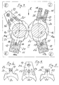
- the cutting unit shown first shows scraper plates 7 for the cutting rollers 1, 2, in which strippers 7, which are mounted over the entire roller width B between two disk-like cutting blades 3, 4 via rods 5 and 6 in the side plates P, are sector-like and with an adapted radius R extend to the roller core la, 2a and additional Wiper elements rest on the surface or the outer circumference 3a, 4a of the cutting disks or circular knives 3, 4.
- the novelty is that the holding rods 5, 6 for the wipers 7 are designed in the form of strips and that, on the one hand, the areas 5a and 6a adjacent to the cutting rollers 1, 2 rest positively on the outer circumference 3a, 4a of the circular knives 3, 4 and on the other hand have a hook-shaped taper 5b or 6b, which engage in an undercut groove 7b on the back of each scraper plate 7, the holding rods 5 and 6 for the scraper plates 7 being mirror images of one another in cross section and at a distance x from one another, diverging from respective rod base 5a or 6a forth individual strips 1, 2 are formed and the connection between rod base 5a or 6a and groove 7b of the stripper plates 7 is dovetail-shaped.
- a very special advantage of the dovetail design is, however, that the sensitive tip parts (lugs 7a) of the stripper plates 7 are held directly by the dovetail base 7b of the stripper strips according to the dash-dotted line K and are thus strengthened or supported in terms of strength. Also important is the smooth outer contour of the strips 5 and 6, on which no particles can therefore adhere.
- the stripping lugs 7a on the side of the cutting gap Sp are at different distances a, b, c, d from the center M of the overlap of the cutting disks 3 and 4, the sum of the Total distances a + b and c + d from nose 7a to nose 7a are different in size for each of the two cutting rollers 1 and 2, respectively.
- the main result of this is that the fibrous clumps of cuttings W inevitably adhering to the scraper noses 7a on the cut material exit side A do not reach the center M of the cutting disc overlap area at the same time as the roll is returning and there, in addition to the material already present in the cutting gap, are pressed and solidified on the roll base becomes.
- this arrangement guarantees that such material never reaches the scraper noses 7a on the paper feed side E at the same time, but always one after the other, thus virtually halving the sum of the scraper resistances for the drive, or greatly reducing the impact load.
- the cutting rollers 1, 2 are coupled to the drive wheel 10 via gear wheels 8, 9.
- the wiper strips are clamped by screws 11 in the bearing or housing side plates P, in which the roller bearings 12 are also located.
- types I to IV of the wiper strips are also to be used to solve the same problem, as indicated by FIGS. 3 to 6 bar, in which the individual stripper plates 20, 20 ⁇ or 20 ⁇ have a socket-like extension 24 or 25 or 26 which protrudes from the outer circumference 13a or 14a of the circular knives 13 and 14 and projects into the space between the stripper strips 15 to 18 and is penetrated by at least one continuous fastening rod 19.
- the special design in detail provides that the areas of the scraper strips 15 to 18 which are in each case form-fitting on the outer circumference 13a and 14a of the circular knives 13 and 14 engage in corresponding grooves 21 and 22 of the scraper plates 20 and 20 'or corresponding recesses 23 in these 20 ⁇ penetrate, wherein in variants II and III the paired wiper strips 17 and 18 are connected to each other by back parts 17a and 18a and thus embrace the bases 24 and 25 of the wiper plates 20 and 20 ⁇ like a hood.
- the wiper strips are each connected by screws 11 to the side plates P of the device housing.
Landscapes
- Engineering & Computer Science (AREA)
- Food Science & Technology (AREA)
- Crushing And Pulverization Processes (AREA)
Applications Claiming Priority (4)
| Application Number | Priority Date | Filing Date | Title |
|---|---|---|---|
| DE3610537A DE3610537C2 (de) | 1986-03-27 | 1986-03-27 | Abstreifer für die Schneidwalzen von Aktenvernichtern |
| DE3610537 | 1986-03-27 | ||
| DE19863610539 DE3610539C2 (de) | 1986-03-27 | 1986-03-27 | Abstreifereinheit für das Schneidwalzenpaar eines Aktenvernichters |
| DE3610539 | 1986-03-27 |
Publications (3)
| Publication Number | Publication Date |
|---|---|
| EP0239104A2 true EP0239104A2 (fr) | 1987-09-30 |
| EP0239104A3 EP0239104A3 (en) | 1988-08-03 |
| EP0239104B1 EP0239104B1 (fr) | 1991-06-05 |
Family
ID=25842427
Family Applications (1)
| Application Number | Title | Priority Date | Filing Date |
|---|---|---|---|
| EP87104455A Expired - Lifetime EP0239104B1 (fr) | 1986-03-27 | 1987-03-26 | Dispositif de coupe pour déchiqueteur de documents |
Country Status (2)
| Country | Link |
|---|---|
| EP (1) | EP0239104B1 (fr) |
| DE (1) | DE3770503D1 (fr) |
Cited By (6)
| Publication number | Priority date | Publication date | Assignee | Title |
|---|---|---|---|---|
| FR2674147A1 (fr) * | 1991-03-22 | 1992-09-25 | Schleicher & Co Int | Destructeur de documents. |
| EP0525491A1 (fr) * | 1991-07-13 | 1993-02-03 | Hermann Schwelling | Racleur pour un petit destructeur de document |
| WO1993025312A1 (fr) * | 1992-06-12 | 1993-12-23 | Erema Engineering Recycling Maschinen Und Anlagen Gesellschaft M.B.H. | Dispositif pour la plastification d'une matiere thermoplastique |
| EP0616850A3 (fr) * | 1993-03-22 | 1995-01-25 | Hermann Schwelling | Destructeur de documents. |
| WO2016070948A1 (fr) | 2014-11-07 | 2016-05-12 | Akten-Ex Gmbh & Co Kg | Destruction de papier écrit |
| CN110064477A (zh) * | 2019-04-29 | 2019-07-30 | 杭州铭展网络科技有限公司 | 一种便于维护的碎纸机 |
Family Cites Families (4)
| Publication number | Priority date | Publication date | Assignee | Title |
|---|---|---|---|---|
| DE2749482C2 (de) * | 1977-11-04 | 1986-01-09 | Feinwerktechnik Schleicher & Co, 7778 Markdorf | Schneidwalze eines Reißwerkes |
| FR2502980B1 (fr) * | 1981-03-31 | 1986-05-16 | Schwelling Hermann | Mecanisme coupeur pour destructeur de documents |
| DE3112666A1 (de) * | 1981-03-31 | 1982-10-14 | Feinwerktechnik Schleicher & Co, 7778 Markdorf | Abstreiffinger im reisswerk einer zerreissmaschine fuer text- und datentraeger |
| DE3577514D1 (de) * | 1984-08-31 | 1990-06-13 | Mochizuki Precision Machine | Schneidmaschine. |
-
1987
- 1987-03-26 DE DE8787104455T patent/DE3770503D1/de not_active Expired - Lifetime
- 1987-03-26 EP EP87104455A patent/EP0239104B1/fr not_active Expired - Lifetime
Cited By (10)
| Publication number | Priority date | Publication date | Assignee | Title |
|---|---|---|---|---|
| FR2674147A1 (fr) * | 1991-03-22 | 1992-09-25 | Schleicher & Co Int | Destructeur de documents. |
| EP0525491A1 (fr) * | 1991-07-13 | 1993-02-03 | Hermann Schwelling | Racleur pour un petit destructeur de document |
| WO1993025312A1 (fr) * | 1992-06-12 | 1993-12-23 | Erema Engineering Recycling Maschinen Und Anlagen Gesellschaft M.B.H. | Dispositif pour la plastification d'une matiere thermoplastique |
| AU668184B2 (en) * | 1992-06-12 | 1996-04-26 | Helmut Bacher | Device for plasticising thermoplastic material |
| EP0616850A3 (fr) * | 1993-03-22 | 1995-01-25 | Hermann Schwelling | Destructeur de documents. |
| WO2016070948A1 (fr) | 2014-11-07 | 2016-05-12 | Akten-Ex Gmbh & Co Kg | Destruction de papier écrit |
| DE202015009627U1 (de) | 2014-11-07 | 2018-11-15 | Akten-Ex Gmbh & Co. Kg | Papier aus einer Aktenvernichtung |
| DE202015009629U1 (de) | 2014-11-07 | 2018-11-15 | Akten-Ex Gmbh & Co. Kg | Anlage zur Aktenvernichtung |
| DE202015009626U1 (de) | 2014-11-07 | 2018-11-15 | Akten-Ex Gmbh & Co. Kg | Aktenvernichter |
| CN110064477A (zh) * | 2019-04-29 | 2019-07-30 | 杭州铭展网络科技有限公司 | 一种便于维护的碎纸机 |
Also Published As
| Publication number | Publication date |
|---|---|
| DE3770503D1 (de) | 1991-07-11 |
| EP0239104B1 (fr) | 1991-06-05 |
| EP0239104A3 (en) | 1988-08-03 |
Similar Documents
| Publication | Publication Date | Title |
|---|---|---|
| EP0497170B1 (fr) | Déchiqueteur de documents comportant un convoyeur pour la matière à déchiqueter | |
| WO1994017981A1 (fr) | Dispositif filtrant pour fluides, notamment pour fluides thermoplastiques | |
| EP0422272B1 (fr) | Dispositif de malaxage et pétrissage | |
| DE3712953A1 (de) | Schneidwerkzeug | |
| EP0239104B1 (fr) | Dispositif de coupe pour déchiqueteur de documents | |
| DE3610537A1 (de) | Abstreifer fuer die schneidwalzen von aktenvernichtern | |
| DE2338654C2 (de) | Zerkleinerungsvorrichtung, insbesondere Aktenvernichter | |
| DE4242740A1 (de) | Zerkleinerungsmaschine | |
| DE3539098A1 (de) | Abfall-zerkleinerungsvorrichtung sowie scherglied fuer diese | |
| EP0291774A2 (fr) | Déchiqueteur à lames rotatives | |
| DE3925098A1 (de) | Einrichtung zum zerkleinern von material | |
| EP0861696A1 (fr) | Disque pour tamis ou séparateur | |
| DE4301787C1 (de) | Messer für Fleischwölfe | |
| DE3509004A1 (de) | Bandschleifmaschine | |
| DE3112838C2 (de) | Schneidwerk für Aktenvernichter | |
| EP0635306A2 (fr) | Dispositif racleur pour destructeur de documents | |
| DE2618254A1 (de) | Messertrommel, insbesondere fuer hackmaschinen zur zerkleinerung von hoelzern und abfaellen | |
| EP0713726A2 (fr) | Broyeur pour copeaux métalliques | |
| DE3610539A1 (de) | Abstreifereinheit fuer das schneidwalzenpaar eines aktenvernichters | |
| DE3622243C2 (de) | Zerkleinerungsvorrichtung, insbesondere zum Vernichten von Informationsträgern | |
| DE4123293A1 (de) | Abstreiferkamm, insbesondere fuer klein-aktenvernichter | |
| AT399844B (de) | Filtervorrichtung, insbesondere für thermoplastische kunststoffschmelzen | |
| DE19650138C2 (de) | Scheibensieb | |
| DE69608376T2 (de) | Schervorrichtung für verschiedenartige Körper | |
| EP0706828B1 (fr) | Dispositif de coupe, pour déchiqueteur en particulier pour déchiqueteur de documents et procédé de réalisation d'un ensemble racleur pour celui-ci |
Legal Events
| Date | Code | Title | Description |
|---|---|---|---|
| PUAI | Public reference made under article 153(3) epc to a published international application that has entered the european phase |
Free format text: ORIGINAL CODE: 0009012 |
|
| AK | Designated contracting states |
Kind code of ref document: A2 Designated state(s): DE FR GB |
|
| PUAL | Search report despatched |
Free format text: ORIGINAL CODE: 0009013 |
|
| AK | Designated contracting states |
Kind code of ref document: A3 Designated state(s): DE FR GB |
|
| 17P | Request for examination filed |
Effective date: 19890111 |
|
| 17Q | First examination report despatched |
Effective date: 19890612 |
|
| RAP1 | Party data changed (applicant data changed or rights of an application transferred) |
Owner name: H.S.M. PRESSEN GMBH |
|
| RIN1 | Information on inventor provided before grant (corrected) |
Inventor name: SCHWELLING, HERMANN |
|
| GRAA | (expected) grant |
Free format text: ORIGINAL CODE: 0009210 |
|
| AK | Designated contracting states |
Kind code of ref document: B1 Designated state(s): DE FR GB |
|
| REF | Corresponds to: |
Ref document number: 3770503 Country of ref document: DE Date of ref document: 19910711 |
|
| GBT | Gb: translation of ep patent filed (gb section 77(6)(a)/1977) | ||
| ET | Fr: translation filed | ||
| PLBE | No opposition filed within time limit |
Free format text: ORIGINAL CODE: 0009261 |
|
| STAA | Information on the status of an ep patent application or granted ep patent |
Free format text: STATUS: NO OPPOSITION FILED WITHIN TIME LIMIT |
|
| 26N | No opposition filed | ||
| PGFP | Annual fee paid to national office [announced via postgrant information from national office to epo] |
Ref country code: FR Payment date: 19970221 Year of fee payment: 11 |
|
| PGFP | Annual fee paid to national office [announced via postgrant information from national office to epo] |
Ref country code: DE Payment date: 19970314 Year of fee payment: 11 |
|
| PGFP | Annual fee paid to national office [announced via postgrant information from national office to epo] |
Ref country code: GB Payment date: 19970321 Year of fee payment: 11 |
|
| PG25 | Lapsed in a contracting state [announced via postgrant information from national office to epo] |
Ref country code: DE Effective date: 19971223 |
|
| PG25 | Lapsed in a contracting state [announced via postgrant information from national office to epo] |
Ref country code: GB Free format text: LAPSE BECAUSE OF NON-PAYMENT OF DUE FEES Effective date: 19980326 |
|
| PG25 | Lapsed in a contracting state [announced via postgrant information from national office to epo] |
Ref country code: FR Free format text: THE PATENT HAS BEEN ANNULLED BY A DECISION OF A NATIONAL AUTHORITY Effective date: 19980331 |
|
| GBPC | Gb: european patent ceased through non-payment of renewal fee |
Effective date: 19980326 |
|
| REG | Reference to a national code |
Ref country code: FR Ref legal event code: ST |