EP0713726A2 - Broyeur pour copeaux métalliques - Google Patents
Broyeur pour copeaux métalliques Download PDFInfo
- Publication number
- EP0713726A2 EP0713726A2 EP95118028A EP95118028A EP0713726A2 EP 0713726 A2 EP0713726 A2 EP 0713726A2 EP 95118028 A EP95118028 A EP 95118028A EP 95118028 A EP95118028 A EP 95118028A EP 0713726 A2 EP0713726 A2 EP 0713726A2
- Authority
- EP
- European Patent Office
- Prior art keywords
- knives
- knife
- chip
- chip shredder
- sieve
- Prior art date
- Legal status (The legal status is an assumption and is not a legal conclusion. Google has not performed a legal analysis and makes no representation as to the accuracy of the status listed.)
- Withdrawn
Links
Images


Classifications
-
- B—PERFORMING OPERATIONS; TRANSPORTING
- B02—CRUSHING, PULVERISING, OR DISINTEGRATING; PREPARATORY TREATMENT OF GRAIN FOR MILLING
- B02C—CRUSHING, PULVERISING, OR DISINTEGRATING IN GENERAL; MILLING GRAIN
- B02C18/00—Disintegrating by knives or other cutting or tearing members which chop material into fragments
- B02C18/06—Disintegrating by knives or other cutting or tearing members which chop material into fragments with rotating knives
- B02C18/14—Disintegrating by knives or other cutting or tearing members which chop material into fragments with rotating knives within horizontal containers
- B02C18/142—Disintegrating by knives or other cutting or tearing members which chop material into fragments with rotating knives within horizontal containers with two or more inter-engaging rotatable cutter assemblies
-
- B—PERFORMING OPERATIONS; TRANSPORTING
- B02—CRUSHING, PULVERISING, OR DISINTEGRATING; PREPARATORY TREATMENT OF GRAIN FOR MILLING
- B02C—CRUSHING, PULVERISING, OR DISINTEGRATING IN GENERAL; MILLING GRAIN
- B02C18/00—Disintegrating by knives or other cutting or tearing members which chop material into fragments
- B02C18/06—Disintegrating by knives or other cutting or tearing members which chop material into fragments with rotating knives
- B02C18/16—Details
- B02C18/18—Knives; Mountings thereof
- B02C18/182—Disc-shaped knives
-
- B—PERFORMING OPERATIONS; TRANSPORTING
- B02—CRUSHING, PULVERISING, OR DISINTEGRATING; PREPARATORY TREATMENT OF GRAIN FOR MILLING
- B02C—CRUSHING, PULVERISING, OR DISINTEGRATING IN GENERAL; MILLING GRAIN
- B02C23/00—Auxiliary methods or auxiliary devices or accessories specially adapted for crushing or disintegrating not provided for in preceding groups or not specially adapted to apparatus covered by a single preceding group
- B02C23/08—Separating or sorting of material, associated with crushing or disintegrating
- B02C23/16—Separating or sorting of material, associated with crushing or disintegrating with separator defining termination of crushing or disintegrating zone, e.g. screen denying egress of oversize material
- B02C2023/165—Screen denying egress of oversize material
Definitions
- the present invention relates to a chip shredder according to the preamble of the main claim.
- Chip shredders of this type are used to shred the chips produced in the machining of metal, plastic or wood workpieces in lathes, milling machines or automatic processing machines. Because of their contamination and poor handling, these chips represent a problem in the reuse (recycling) of the chip material.
- the chip shredders that have been known in this way are not yet suitable in terms of their performance in terms of their susceptibility to malfunction and safe continuous crushing and service life fulfill.
- the present invention is therefore based on the object of proposing an improved chip shredder, in particular for metals.
- the chip shredder designed according to the invention has a sieve which is only provided with sieve holes under the respective knife.
- the diameter of the screen holes depends on the size and type of chips to be processed or the desired size of the chips.
- the thickness of the sieve must also be adjusted accordingly.
- rinsing bores are additionally arranged between the individual rows of the screen holes.
- the rinsing holes are located under the gaps between the knives arranged on a shaft. Using the flushing holes, smaller chips that accumulate in this area can be flushed away using a flushing liquid.
- the screens are made of steel as a sheet metal part with the alloy additives 0.15-0.22% carbon, 0.20-0.65% silicon, 1.0-1.7% manganese, ⁇ 0.025% phosphorus, ⁇ 0.025% sulfur, 0.80-1.5% chromium, ⁇ 0.50% copper, ⁇ 0.30% molybdenum and ⁇ 0.60% nickel.
- the alloy additives 0.15-0.22% carbon, 0.20-0.65% silicon, 1.0-1.7% manganese, ⁇ 0.025% phosphorus, ⁇ 0.025% sulfur, 0.80-1.5% chromium, ⁇ 0.50% copper, ⁇ 0.30% molybdenum and ⁇ 0.60% nickel.
- Such a material is known under the designations VSS 295 and VSS 296 with the materials no. 1.8704 and 1.8705 and ensures a long service life when shredding metal chips. It is only through the use of such a material that it is ensured that the metal chips can be shredded over a long period of time without disruption.
- a magnet is additionally provided, which can be inserted into the gusset between the knives to remove these parts. If magnetic, these objects can be removed using the magnet.
- the knives stick to the magnetic (iron) workpieces so that the device comes to a standstill.
- the knives are then moved in the opposite direction of rotation by means of a corresponding control in order to release the space and, if appropriate, the workpiece for removal by the magnet. Due to the power of the knives, it can be expected that non-magnetic parts will gradually be scraped off and crushed.
- the knives used for the chip shredder have a disk-shaped knife body from which at least two hook-shaped knife teeth protrude, the inner radii of which point in the direction of rotation.
- the knives are used to pull the chips down and to shred them between the edges of the knife body that are juxtaposed. The further comminution then takes place between these knife teeth and the inner surface of the sieve until the chip chips fit through the respective sieve holes.
- the knives have at least two essentially symmetrical knife teeth which protrude from the knife body and are hook-shaped in both directions of rotation. These knives are particularly advantageous when crimp-like shavings are placed around the shafts so that they can no longer be grasped and shredded by the knives of the other row of knives. These specially designed knife teeth are then used for reversing the direction of rotation for broaching and subsequent comminution.
- the chip shredder designed in accordance with the invention is characterized by a long service life and operational reliability and allows the safe shredding of all chips and chip shapes that occur.
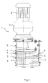
- Figure 1 shows the chip shredder 1 with a motor 2, a gear 3 and the chip shredding room 4.
- the chip shredding room 4 there are two shafts 5 and 6 on which two rows of knives are arranged.
- the knives 7 of a row of knives are arranged at a distance from one another and mesh with the knives of the second row of knives.
- the spacing of the shafts from one another is designed such that the knives 7 protrude as far as possible into the space 8 between the knives of the other row of knives.
- the chips are pre-shredded by the shear effect between the individual knife bodies.
- the schematically indicated magnet 9 can be extended via the knives and serves to remove larger parts from the chip shredding area.
- FIG. 2 shows the chip shredder with the shafts 5 and 6 arranged in the chip shredding chamber 4 and the knives 7 located thereon.
- a sieve 10 with curved sieve surfaces, the radius of which corresponds to the radius of the knife teeth 11, so that the distance between the knife tooth 11 and the surface of the sieve 10 is as small as possible. The distance depends on the size of the chips you want.
- the crushing takes place by rubbing the chips between the knife teeth 11 and the surface of the sieves 10.
- the sieves are made of the particularly wear-resistant material VSS 295.
- the cutting speed of the knives is 5 to 12 meters per minute depending on the amount to be shredded and the size of the chips.
- Figure 3 shows an embodiment of a sieve 10. It can be clearly seen that the sieve holes are each arranged only under the respective knife. The two halves of the screen are rotated 90 ° against each other.
- FIG. 4 shows another embodiment of a sieve 10, only one half of the sieve being shown here.
- rinsing holes 13 are still provided between the individual sieve holes 12 for cleaning the sieve and removing smaller parts.
- FIG. 5 shows a knife 7 with four knife teeth 11 ′, which are configured symmetrically and protrude from the knife body 15.
- the knife teeth 11 ' are hook-shaped on each side, so that this knife shape is suitable for removing chips wound around the shaft by reversing the direction of rotation and feeding them in an orderly comminution.
- FIG. 6 shows another embodiment of a knife 7 with knife teeth 11 ′′ which are hook-shaped only on one side in order to take the chips with this side and to feed them down.
Applications Claiming Priority (2)
| Application Number | Priority Date | Filing Date | Title |
|---|---|---|---|
| DE9418904U | 1994-11-25 | ||
| DE9418904U DE9418904U1 (de) | 1994-11-25 | 1994-11-25 | Spänezerkleinerer |
Publications (2)
| Publication Number | Publication Date |
|---|---|
| EP0713726A2 true EP0713726A2 (fr) | 1996-05-29 |
| EP0713726A3 EP0713726A3 (fr) | 1996-07-17 |
Family
ID=6916594
Family Applications (1)
| Application Number | Title | Priority Date | Filing Date |
|---|---|---|---|
| EP95118028A Withdrawn EP0713726A3 (fr) | 1994-11-25 | 1995-11-16 | Broyeur pour copeaux métalliques |
Country Status (2)
| Country | Link |
|---|---|
| EP (1) | EP0713726A3 (fr) |
| DE (1) | DE9418904U1 (fr) |
Cited By (3)
| Publication number | Priority date | Publication date | Assignee | Title |
|---|---|---|---|---|
| FR2812565A1 (fr) * | 2000-08-01 | 2002-02-08 | S M P In Pere & Fils Fa | Element de broyage pour un broyeur pour dechets de matieres plastiques |
| DE102004012200A1 (de) * | 2004-03-12 | 2005-09-29 | Bürener Maschinenfabrik GmbH | Spänebrecher |
| CN104624326A (zh) * | 2014-12-24 | 2015-05-20 | 常熟市首誉机械有限公司 | 金属撕碎装置 |
Families Citing this family (4)
| Publication number | Priority date | Publication date | Assignee | Title |
|---|---|---|---|---|
| DE10006757C1 (de) | 2000-02-15 | 2001-05-17 | Mayfran Int Bv | Verfahren und Vorrichtungen zum Zerkleinern von Spänen |
| DE10112510C2 (de) * | 2001-03-09 | 2003-07-31 | Aps Glass & Bar Supply Gmbh | Vorrichtung zum Zerkleinern von Eiswürfeln |
| DE202006015467U1 (de) * | 2006-09-29 | 2008-02-07 | Seg Basis Gmbh | Mehrwellen-Zerkleinerer |
| DE102009052750A1 (de) | 2009-11-11 | 2011-05-19 | Bürener Maschinenfabrik GmbH | Spänebrecher |
Family Cites Families (6)
| Publication number | Priority date | Publication date | Assignee | Title |
|---|---|---|---|---|
| DE251531C (fr) * | ||||
| DE421055C (de) * | 1924-11-27 | 1925-11-05 | Eduard Pfahler | Aus gelochtem Blech und Drahtlamellen bestehende Siebplatte fuer Schleudermuehlen |
| GB1258764A (fr) * | 1968-10-16 | 1971-12-30 | ||
| US4385732A (en) * | 1980-08-29 | 1983-05-31 | Williams Robert M | Waste material breaking and shredding apparatus |
| US5199666A (en) * | 1992-01-03 | 1993-04-06 | Williams Robert M | Rotary shredding apparatus with oscillating grate |
| JPH06238187A (ja) * | 1993-02-18 | 1994-08-30 | Ootsuka Tec:Kk | 金属切屑破砕機 |
-
1994
- 1994-11-25 DE DE9418904U patent/DE9418904U1/de not_active Expired - Lifetime
-
1995
- 1995-11-16 EP EP95118028A patent/EP0713726A3/fr not_active Withdrawn
Non-Patent Citations (1)
| Title |
|---|
| None |
Cited By (4)
| Publication number | Priority date | Publication date | Assignee | Title |
|---|---|---|---|---|
| FR2812565A1 (fr) * | 2000-08-01 | 2002-02-08 | S M P In Pere & Fils Fa | Element de broyage pour un broyeur pour dechets de matieres plastiques |
| DE102004012200A1 (de) * | 2004-03-12 | 2005-09-29 | Bürener Maschinenfabrik GmbH | Spänebrecher |
| DE102004012200B4 (de) * | 2004-03-12 | 2007-08-30 | Bürener Maschinenfabrik GmbH | Spänebrecher |
| CN104624326A (zh) * | 2014-12-24 | 2015-05-20 | 常熟市首誉机械有限公司 | 金属撕碎装置 |
Also Published As
| Publication number | Publication date |
|---|---|
| EP0713726A3 (fr) | 1996-07-17 |
| DE9418904U1 (de) | 1995-03-16 |
Similar Documents
| Publication | Publication Date | Title |
|---|---|---|
| EP2218507B1 (fr) | Dispositif de broyage de matériaux de chargement dotés d'éléments de démoulage | |
| DE2730188A1 (de) | Zerkleinerungsmaschine | |
| DE102010036851B4 (de) | Vorrichtung zum Zerkleinern von Material | |
| EP0005726B1 (fr) | Outil de coupe pour machine à hacher les aliments | |
| DE3112639C2 (fr) | ||
| DE10338682B4 (de) | Vorrichtung zum Bearbeiten von im wesentlichen flachen Werkstücken | |
| EP0422272B1 (fr) | Dispositif de malaxage et pétrissage | |
| EP0387868B1 (fr) | Dispositif de broyage pour déchets de bois | |
| EP0713726A2 (fr) | Broyeur pour copeaux métalliques | |
| EP0998980B1 (fr) | Désintégrateur à arbres parallèles entraínés par moteur | |
| DE3345800C2 (de) | Vorrichtung zum Herstellen und Bearbeiten von Zahnrädern | |
| EP0425630B1 (fr) | Garniture de triturage d'un raffineur conique | |
| EP2335829A1 (fr) | Dispositif de broyage de copeaux | |
| EP0595048A2 (fr) | Dispositif de prébrayage et de dosage, en particulier pour de grandes installations de déchiquetage de documents et autres déchets | |
| DE2357765A1 (de) | Vorrichtung zur zerkleinerung von abfallstoffen | |
| DE102019108306A1 (de) | Schneidmühle zum schneidenden Zerkleinern von Proben | |
| EP0037036B1 (fr) | Déchiqueteur rotatif pour le broyage de déchets | |
| DE3102420C2 (de) | Schneidwerk zum Aufbereiten von mit hohem Faseranteil durchsetzten Flüssigkeiten | |
| EP0712663A1 (fr) | Broyeur pour copeaux métalliques | |
| DE3231341C2 (fr) | ||
| DE1914413C3 (de) | Grobstoffzerkleinerer | |
| DE3908395A1 (de) | Vorrichtung zum zerkleinern von rest- und abfallhoelzern | |
| EP0401573A2 (fr) | Dispositif pour couper des produits en plastique | |
| EP0847805A1 (fr) | Outil de coupe pour transporteur rotatif à vis | |
| DE2618254A1 (de) | Messertrommel, insbesondere fuer hackmaschinen zur zerkleinerung von hoelzern und abfaellen |
Legal Events
| Date | Code | Title | Description |
|---|---|---|---|
| PUAI | Public reference made under article 153(3) epc to a published international application that has entered the european phase |
Free format text: ORIGINAL CODE: 0009012 |
|
| AK | Designated contracting states |
Kind code of ref document: A2 Designated state(s): AT DE FR GB IT SE |
|
| PUAL | Search report despatched |
Free format text: ORIGINAL CODE: 0009013 |
|
| 17P | Request for examination filed |
Effective date: 19960515 |
|
| AK | Designated contracting states |
Kind code of ref document: A3 Designated state(s): AT DE FR GB IT SE |
|
| 17Q | First examination report despatched |
Effective date: 19960902 |
|
| STAA | Information on the status of an ep patent application or granted ep patent |
Free format text: STATUS: THE APPLICATION IS DEEMED TO BE WITHDRAWN |
|
| 18D | Application deemed to be withdrawn |
Effective date: 19970313 |