EP0713726A2 - Metal-chip comminuting device - Google Patents
Metal-chip comminuting device Download PDFInfo
- Publication number
- EP0713726A2 EP0713726A2 EP95118028A EP95118028A EP0713726A2 EP 0713726 A2 EP0713726 A2 EP 0713726A2 EP 95118028 A EP95118028 A EP 95118028A EP 95118028 A EP95118028 A EP 95118028A EP 0713726 A2 EP0713726 A2 EP 0713726A2
- Authority
- EP
- European Patent Office
- Prior art keywords
- knives
- knife
- chip
- chip shredder
- sieve
- Prior art date
- Legal status (The legal status is an assumption and is not a legal conclusion. Google has not performed a legal analysis and makes no representation as to the accuracy of the status listed.)
- Withdrawn
Links
Images


Classifications
-
- B—PERFORMING OPERATIONS; TRANSPORTING
- B02—CRUSHING, PULVERISING, OR DISINTEGRATING; PREPARATORY TREATMENT OF GRAIN FOR MILLING
- B02C—CRUSHING, PULVERISING, OR DISINTEGRATING IN GENERAL; MILLING GRAIN
- B02C18/00—Disintegrating by knives or other cutting or tearing members which chop material into fragments
- B02C18/06—Disintegrating by knives or other cutting or tearing members which chop material into fragments with rotating knives
- B02C18/14—Disintegrating by knives or other cutting or tearing members which chop material into fragments with rotating knives within horizontal containers
- B02C18/142—Disintegrating by knives or other cutting or tearing members which chop material into fragments with rotating knives within horizontal containers with two or more inter-engaging rotatable cutter assemblies
-
- B—PERFORMING OPERATIONS; TRANSPORTING
- B02—CRUSHING, PULVERISING, OR DISINTEGRATING; PREPARATORY TREATMENT OF GRAIN FOR MILLING
- B02C—CRUSHING, PULVERISING, OR DISINTEGRATING IN GENERAL; MILLING GRAIN
- B02C18/00—Disintegrating by knives or other cutting or tearing members which chop material into fragments
- B02C18/06—Disintegrating by knives or other cutting or tearing members which chop material into fragments with rotating knives
- B02C18/16—Details
- B02C18/18—Knives; Mountings thereof
- B02C18/182—Disc-shaped knives
-
- B—PERFORMING OPERATIONS; TRANSPORTING
- B02—CRUSHING, PULVERISING, OR DISINTEGRATING; PREPARATORY TREATMENT OF GRAIN FOR MILLING
- B02C—CRUSHING, PULVERISING, OR DISINTEGRATING IN GENERAL; MILLING GRAIN
- B02C23/00—Auxiliary methods or auxiliary devices or accessories specially adapted for crushing or disintegrating not provided for in preceding groups or not specially adapted to apparatus covered by a single preceding group
- B02C23/08—Separating or sorting of material, associated with crushing or disintegrating
- B02C23/16—Separating or sorting of material, associated with crushing or disintegrating with separator defining termination of crushing or disintegrating zone, e.g. screen denying egress of oversize material
- B02C2023/165—Screen denying egress of oversize material
Definitions
- the present invention relates to a chip shredder according to the preamble of the main claim.
- Chip shredders of this type are used to shred the chips produced in the machining of metal, plastic or wood workpieces in lathes, milling machines or automatic processing machines. Because of their contamination and poor handling, these chips represent a problem in the reuse (recycling) of the chip material.
- the chip shredders that have been known in this way are not yet suitable in terms of their performance in terms of their susceptibility to malfunction and safe continuous crushing and service life fulfill.
- the present invention is therefore based on the object of proposing an improved chip shredder, in particular for metals.
- the chip shredder designed according to the invention has a sieve which is only provided with sieve holes under the respective knife.
- the diameter of the screen holes depends on the size and type of chips to be processed or the desired size of the chips.
- the thickness of the sieve must also be adjusted accordingly.
- rinsing bores are additionally arranged between the individual rows of the screen holes.
- the rinsing holes are located under the gaps between the knives arranged on a shaft. Using the flushing holes, smaller chips that accumulate in this area can be flushed away using a flushing liquid.
- the screens are made of steel as a sheet metal part with the alloy additives 0.15-0.22% carbon, 0.20-0.65% silicon, 1.0-1.7% manganese, ⁇ 0.025% phosphorus, ⁇ 0.025% sulfur, 0.80-1.5% chromium, ⁇ 0.50% copper, ⁇ 0.30% molybdenum and ⁇ 0.60% nickel.
- the alloy additives 0.15-0.22% carbon, 0.20-0.65% silicon, 1.0-1.7% manganese, ⁇ 0.025% phosphorus, ⁇ 0.025% sulfur, 0.80-1.5% chromium, ⁇ 0.50% copper, ⁇ 0.30% molybdenum and ⁇ 0.60% nickel.
- Such a material is known under the designations VSS 295 and VSS 296 with the materials no. 1.8704 and 1.8705 and ensures a long service life when shredding metal chips. It is only through the use of such a material that it is ensured that the metal chips can be shredded over a long period of time without disruption.
- a magnet is additionally provided, which can be inserted into the gusset between the knives to remove these parts. If magnetic, these objects can be removed using the magnet.
- the knives stick to the magnetic (iron) workpieces so that the device comes to a standstill.
- the knives are then moved in the opposite direction of rotation by means of a corresponding control in order to release the space and, if appropriate, the workpiece for removal by the magnet. Due to the power of the knives, it can be expected that non-magnetic parts will gradually be scraped off and crushed.
- the knives used for the chip shredder have a disk-shaped knife body from which at least two hook-shaped knife teeth protrude, the inner radii of which point in the direction of rotation.
- the knives are used to pull the chips down and to shred them between the edges of the knife body that are juxtaposed. The further comminution then takes place between these knife teeth and the inner surface of the sieve until the chip chips fit through the respective sieve holes.
- the knives have at least two essentially symmetrical knife teeth which protrude from the knife body and are hook-shaped in both directions of rotation. These knives are particularly advantageous when crimp-like shavings are placed around the shafts so that they can no longer be grasped and shredded by the knives of the other row of knives. These specially designed knife teeth are then used for reversing the direction of rotation for broaching and subsequent comminution.
- the chip shredder designed in accordance with the invention is characterized by a long service life and operational reliability and allows the safe shredding of all chips and chip shapes that occur.
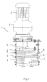
- Figure 1 shows the chip shredder 1 with a motor 2, a gear 3 and the chip shredding room 4.
- the chip shredding room 4 there are two shafts 5 and 6 on which two rows of knives are arranged.
- the knives 7 of a row of knives are arranged at a distance from one another and mesh with the knives of the second row of knives.
- the spacing of the shafts from one another is designed such that the knives 7 protrude as far as possible into the space 8 between the knives of the other row of knives.
- the chips are pre-shredded by the shear effect between the individual knife bodies.
- the schematically indicated magnet 9 can be extended via the knives and serves to remove larger parts from the chip shredding area.
- FIG. 2 shows the chip shredder with the shafts 5 and 6 arranged in the chip shredding chamber 4 and the knives 7 located thereon.
- a sieve 10 with curved sieve surfaces, the radius of which corresponds to the radius of the knife teeth 11, so that the distance between the knife tooth 11 and the surface of the sieve 10 is as small as possible. The distance depends on the size of the chips you want.
- the crushing takes place by rubbing the chips between the knife teeth 11 and the surface of the sieves 10.
- the sieves are made of the particularly wear-resistant material VSS 295.
- the cutting speed of the knives is 5 to 12 meters per minute depending on the amount to be shredded and the size of the chips.
- Figure 3 shows an embodiment of a sieve 10. It can be clearly seen that the sieve holes are each arranged only under the respective knife. The two halves of the screen are rotated 90 ° against each other.
- FIG. 4 shows another embodiment of a sieve 10, only one half of the sieve being shown here.
- rinsing holes 13 are still provided between the individual sieve holes 12 for cleaning the sieve and removing smaller parts.
- FIG. 5 shows a knife 7 with four knife teeth 11 ′, which are configured symmetrically and protrude from the knife body 15.
- the knife teeth 11 ' are hook-shaped on each side, so that this knife shape is suitable for removing chips wound around the shaft by reversing the direction of rotation and feeding them in an orderly comminution.
- FIG. 6 shows another embodiment of a knife 7 with knife teeth 11 ′′ which are hook-shaped only on one side in order to take the chips with this side and to feed them down.
Abstract
Description
Die vorliegende Erfindung betrifft einen Spänezerkleinerer gemäß dem Oberbegriff des Hauptanspruchs.The present invention relates to a chip shredder according to the preamble of the main claim.
Derartige Spänezerkleinerer dienen dazu, die bei der Bearbeitung von Werkstücken aus Metall, Kunststoff oder Holz anfallenden Späne bei Drehmaschinen, Fräsmaschinen oder Bearbeitungsautomaten zu zerkleinern. Diese Späne stellen aufgrund Ihrer Verschmutzung und schlechten Handhabbarkeit ein Problem bei der Wiederverwertung (Recycling) des Spanmaterials dar. Die bisher bekannten derart aufgebauten Spänezerkleinerer sind hinsichtlich ihrer Leistungsfähigkeit in Bezug auf Störanfälligkeit und sicherer kontinuierlicher Zerkleinerung sowie Standzeit noch nicht geeignet, die Anforderungen der Anwender zu erfüllen.Chip shredders of this type are used to shred the chips produced in the machining of metal, plastic or wood workpieces in lathes, milling machines or automatic processing machines. Because of their contamination and poor handling, these chips represent a problem in the reuse (recycling) of the chip material. The chip shredders that have been known in this way are not yet suitable in terms of their performance in terms of their susceptibility to malfunction and safe continuous crushing and service life fulfill.
Der vorliegenden Erfindung liegt daher die Aufgabe zugrunde, einen dahingehend verbesserten Spänezerkleinerer, insbesondere für Metalle, vorzuschlagen.The present invention is therefore based on the object of proposing an improved chip shredder, in particular for metals.
Diese Aufgabe wird durch einen Spänezerkleinerer mit den Merkmalen des Hauptanspruchs gelöst. Weitere vorteilhafte Ausgestaltungen sind den Unteransprüchen zu entnehmen.This object is achieved by a chip shredder with the features of the main claim. Further advantageous refinements can be found in the subclaims.
Der erfindungsgemäß ausgestaltete Spänezerkleinerer weist dazu ein Sieb auf, das nur mit Sieblöchern unter dem jeweiligen Messer versehen ist. Der Durchmesser der Sieblöcher richtet sich nach der Größe und der Art der zu verarbeitenden Späne bzw. der gewünschten Größe der Spanschnitzel. Entsprechend ist auch die Dicke des Siebes darauf abzustimmen. Durch die Anordnung der Sieblöcher nur unter dem jeweiligen Messer werden die Späne solange durch die Messer über die Löcher gerieben, bis der jeweilige Span klein genug ist, um durch die Sieblöcher zu gelangen. Aufgrund dieser Anordnung fallen kaum unzerkleinerte Späne an, so daß die Betriebssicherheit der Vorrichtung sichergestellt wird. Diese Zerkleinerung der Späne ermöglicht auch den automatischen Abtransport der Spanschnitzel von der Maschine.To this end, the chip shredder designed according to the invention has a sieve which is only provided with sieve holes under the respective knife. The diameter of the screen holes depends on the size and type of chips to be processed or the desired size of the chips. The thickness of the sieve must also be adjusted accordingly. By arranging the sieve holes only under the respective knife, the chips are rubbed by the knives over the holes until the respective chip is small enough to pass through the sieve holes. Because of this arrangement, there are hardly any shredded chips, so that the operational safety of the device is ensured. This shredding of the chips also enables the chip chips to be automatically removed from the machine.
Gemäß einer bevorzugten Ausführungsform sind zusätzlich Spülbohrungen zwischen den einzelnen Reihen der Sieblöcher angeordnet. Die Spülbohrungen befinden sich unter den Zwischenräumen zwischen den auf einer Welle angeordneten Messern. Mittels der Spülbohrungen können sich in diesem Bereich ansammelnde kleinere Spanschnitzel mittels einer Spülflüssigkeit weggespült werden.According to a preferred embodiment, rinsing bores are additionally arranged between the individual rows of the screen holes. The rinsing holes are located under the gaps between the knives arranged on a shaft. Using the flushing holes, smaller chips that accumulate in this area can be flushed away using a flushing liquid.
Gemäß einer weiteren bevorzugten Ausführungsform sind die Siebe als Blechteil aus Stahl mit den Legierungszusätzen 0,15-0,22 % Kohlenstoff, 0,20-0,65 % Silicium, 1,0-1,7 % Mangan, ≦ 0,025 % Phosphor, ≦ 0,025 % Schwefel, 0,80-1,5 % Chrom, ≦ 0,50 % Kupfer, ≦ 0,30 % Molybdän und ≦ 0,60 % Nickel hergestellt. Ein derartiges Material ist unter der Bezeichnung VSS 295 und VSS 296 mit den Werkstoffen Nr. 1.8704 und 1.8705 bekannt und gewährleistet eine lange Lebensdauer bei der Zerkleinerung von Metallspänen. Nur durch die Verwendung eines derartigen Materials ist sichergestellt, daß die Zerkleinerung von Metallspänen auch über einen langen Zeitraum ohne Störung erfolgen kann.According to a further preferred embodiment, the screens are made of steel as a sheet metal part with the alloy additives 0.15-0.22% carbon, 0.20-0.65% silicon, 1.0-1.7% manganese, ≦ 0.025% phosphorus, ≦ 0.025% sulfur, 0.80-1.5% chromium, ≦ 0.50% copper, ≦ 0.30% molybdenum and ≦ 0.60% nickel. Such a material is known under the designations VSS 295 and VSS 296 with the materials no. 1.8704 and 1.8705 and ensures a long service life when shredding metal chips. It is only through the use of such a material that it is ensured that the metal chips can be shredded over a long period of time without disruption.
Zur Entfernung von größeren nichtschneidbaren Gegenständen, die in den Spänezerkleinerer gelangen können, ist zusätzlich ein Magnet vorgesehen, der zum Entfernen dieser Teile in den Zwickel zwischen den Messern einfahrbar ist. Mittels des Magneten können diese Gegenstände, sofern magnetisch, entfernt werden. Bei den magnetischen (Eisen-) Werkstücken bleiben die Messer hängen, so daß die Einrichtung zum Stillstand kommt. Mittels einer entsprechenden Steuerung werden die Messer dann in entgegengesetzter Drehrichtung bewegt, um den Raum und gegebenenfalls das Werkstück zur Entnahme durch den Magneten freizugeben. Aufgrund der Kraft der Messer ist zu erwarten, daß nichtmagnetische Teile nach und nach abgekratzt und zerkleinert werden. Die für den Spänezerkleinerer verwendeten Messer weisen einen scheibenförmigen Messerkörper auf, aus dem mindestens zwei hakenförmige Messerzähne herausragen, deren Innenradien in Drehrichtung zeigen. Diese Messerzähne dienen dazu, die Späne nach unten zu ziehen und zwischen den aneinanderscherenden Kanten der Messerkörper zu zerkleinern. Die weitere Zerkleinerung erfolgt dann zwischen diesen Messerzähnen und der Innenfläche des Siebes, solange, bis die Spanschnitzel durch die jeweiligen Sieblöcher passen. Gemäß einer bevorzugten Ausführungsform weisen die Messer mindestens zwei im wesentlichen symetrische Messerzahne auf, die aus dem Messerkörper herausragen und in beide Drehrichtungen hakenförmig ausgebildet sind. Diese Messer sind besonders dann vorteilhaft, wenn sich wollenähnlich kräuselnde Späne um die Wellen legen, so daß sie von den Messern der anderen Messerreihe nicht mehr erfaßt und zerkleinert werden können. Diese besonders ausgestalteten Messerzähne werden dann durch Umkehr der Drehrichtung zum Ausräumen und anschließenden Zerkleinern benutzt.To remove larger non-cut objects that can get into the chip shredder, a magnet is additionally provided, which can be inserted into the gusset between the knives to remove these parts. If magnetic, these objects can be removed using the magnet. The knives stick to the magnetic (iron) workpieces so that the device comes to a standstill. The knives are then moved in the opposite direction of rotation by means of a corresponding control in order to release the space and, if appropriate, the workpiece for removal by the magnet. Due to the power of the knives, it can be expected that non-magnetic parts will gradually be scraped off and crushed. The knives used for the chip shredder have a disk-shaped knife body from which at least two hook-shaped knife teeth protrude, the inner radii of which point in the direction of rotation. These knife teeth are used to pull the chips down and to shred them between the edges of the knife body that are juxtaposed. The further comminution then takes place between these knife teeth and the inner surface of the sieve until the chip chips fit through the respective sieve holes. According to a preferred embodiment, the knives have at least two essentially symmetrical knife teeth which protrude from the knife body and are hook-shaped in both directions of rotation. These knives are particularly advantageous when crimp-like shavings are placed around the shafts so that they can no longer be grasped and shredded by the knives of the other row of knives. These specially designed knife teeth are then used for reversing the direction of rotation for broaching and subsequent comminution.
Der erfindungsgemäß ausgestaltete Spänezerkleinerer zeichnet sich durch eine hohe Standzeit und Betriebssicherheit aus und erlaubt die sichere Zerkleinerung von allen anfallenden Spänen und Spanformen.The chip shredder designed in accordance with the invention is characterized by a long service life and operational reliability and allows the safe shredding of all chips and chip shapes that occur.
Nachfolgend wird die Erfindung anhand von Ausführungsbeispielen in Verbindung mit den begleitenden Zeichnungen näher erläutert.The invention is explained in more detail below on the basis of exemplary embodiments in conjunction with the accompanying drawings.
Es stellen dar:
- Figur 1
- eine Draufsicht auf einen Spänezerkleinerer;
Figur 2- einen Querschnitt durch den Spanzerkleinerungsraum;
Figur 3- die Draufsicht auf ein Sieb;
Figur 4- die Draufsicht auf ein anderes Ausführungsbeispiel einer Siebhälfte;
- Figur 5
- die Ansicht einer Messerausführungsform; und
Figur 6- die Ansicht einer anderen Messerausführungsform.
- Figure 1
- a plan view of a chip shredder;
- Figure 2
- a cross section through the chip shredding room;
- Figure 3
- the top view of a sieve;
- Figure 4
- the top view of another embodiment of a screen half;
- Figure 5
- the view of a knife embodiment; and
- Figure 6
- the view of another knife embodiment.
Figur 1 zeigt den Spänezerkleinerer 1 mit einem Motor 2, einem Getriebe 3 und dem Spänezerkleinerungsraum 4. In dem Spänezerkleinerungsraum 4 befinden sich zwei Wellen 5 und 6 auf denen zwei Messerreihen angeordnet sind. Die Messer 7 einer Messerreihe sind mit Abstand zueinander angeordnet und kämmen mit den Messern der zweiten Messerreihe. Die Abstände der Wellen voneinander sind so ausgelegt, daß die Messer 7 möglichst weit in den Zwischenraum 8 zwischen den Messern der anderen Messerreihe hineinragen. Eine Vorzerkleinerung der Späne erfolgt durch die Scherwirkung zwischen den einzelnen Messerkörpern. Der schematisch angedeutete Magnet 9 ist über die Messer ausfahrbar und dient dazu, größere Teile aus dem Spänezerkleinerungsraum zu entfernen.Figure 1 shows the chip shredder 1 with a
Figur 2 zeigt den Spänezerkleinerer mit den in dem Spänezerkleinerungsraum 4 angeordneten Wellen 5 und 6 und den darauf befindlichen Messern 7. Unterhalb der Wellen befinden sich ein Sieb 10 mit bogenförmig ausgestalteten Siebflächen, deren Radius dem Radius der Messerzähne 11 entspricht, so daß der Abstand zwischen dem Messerzahn 11 und der Oberfläche des Siebes 10 möglichst klein ist. Der Abstand richtet sich nach der Größe der gewünschten Spanschnitzel. Die Zerkleinerung erfolgt durch das Reiben der Späne zwischen den Messerzähnen 11 und der Oberfläche der Siebe 10. Die Siebe sind aus dem besonders verschleißfesten Material VSS 295 hergestellt. Die Schnittgeschwindigkeit der Messer beträgt in Abhängigkeit von der zu zerkleinernden Menge und der Größe der Späne 5 bis 12 Meter pro Minute.FIG. 2 shows the chip shredder with the
Figur 3 zeigt ein Ausführungsbeispiel eines Siebes 10. Dabei ist deutlich zu erkennen, daß die Sieblöcher jeweils nur unter dem jeweiligen Messer angeordnet sind. Die beiden Siebhälften sind gegeneinander um 90° gedreht.Figure 3 shows an embodiment of a
Figur 4 zeigt eine andere Ausführungsform eines Siebes 10, wobei hier nur eine Siebhälfte dargestellt ist. Bei dieser Ausführungsform sind zwischen den einzelnen Sieblöcher 12 noch Spüllöcher 13 zur Reinigung des Siebes und Abtransport kleinerer Teile vorgesehen.FIG. 4 shows another embodiment of a
Figur 5 zeigt ein Messer 7 mit vier Messerzähnen 11', die symetrisch ausgestaltet sind und aus dem Messerkörper 15 herausragen. Die Messerzähne 11' sind auf jeder Seite hakenförmig ausgebildet, so daß diese Messerform dafür geeignet ist, durch Umkehr der Drehrichtung um die Welle gewickelte Späne auszuräumen und einer geordneten Zerkleinerung zuzuführen.FIG. 5 shows a
Figur 6 zeigt eine andere Ausgestaltung eines Messers 7 mit Messerzähnen 11'', die nur auf einer Seite hakenförmig ausgebildet sind, um mit dieser Seite die Späne mitzunehmen und der Verkleinerung zuzuführen.FIG. 6 shows another embodiment of a
Claims (6)
Applications Claiming Priority (2)
| Application Number | Priority Date | Filing Date | Title |
|---|---|---|---|
| DE9418904U DE9418904U1 (en) | 1994-11-25 | 1994-11-25 | Chip shredder |
| DE9418904U | 1994-11-25 |
Publications (2)
| Publication Number | Publication Date |
|---|---|
| EP0713726A2 true EP0713726A2 (en) | 1996-05-29 |
| EP0713726A3 EP0713726A3 (en) | 1996-07-17 |
Family
ID=6916594
Family Applications (1)
| Application Number | Title | Priority Date | Filing Date |
|---|---|---|---|
| EP95118028A Withdrawn EP0713726A3 (en) | 1994-11-25 | 1995-11-16 | Metal-chip comminuting device |
Country Status (2)
| Country | Link |
|---|---|
| EP (1) | EP0713726A3 (en) |
| DE (1) | DE9418904U1 (en) |
Cited By (3)
| Publication number | Priority date | Publication date | Assignee | Title |
|---|---|---|---|---|
| FR2812565A1 (en) * | 2000-08-01 | 2002-02-08 | S M P In Pere & Fils Fa | Grinding component for plastic waste grinder |
| DE102004012200A1 (en) * | 2004-03-12 | 2005-09-29 | Bürener Maschinenfabrik GmbH | Woodchip breaker has disintegrator in housing, with blade shafts on peripheral sides rotating crossways to output direction |
| CN104624326A (en) * | 2014-12-24 | 2015-05-20 | 常熟市首誉机械有限公司 | Metal shredding device |
Families Citing this family (4)
| Publication number | Priority date | Publication date | Assignee | Title |
|---|---|---|---|---|
| DE10006757C1 (en) | 2000-02-15 | 2001-05-17 | Mayfran Int Bv | Crushing process for chips or swarf, involving recording rate of alteration of load to detect blocking chips and ejecting these chips |
| DE10112510C2 (en) * | 2001-03-09 | 2003-07-31 | Aps Glass & Bar Supply Gmbh | Device for crushing ice cubes |
| DE202006015467U1 (en) * | 2006-09-29 | 2008-02-07 | Seg Basis Gmbh | More shaft shredder |
| DE102009052750A1 (en) | 2009-11-11 | 2011-05-19 | Bürener Maschinenfabrik GmbH | Chip breaker for cutting chips into short pieces during processing of metal workpiece, has strippers engaging in gaps of blades, and head surfaces that are positioned opposite to circular peripheral surface provided at shafts |
Family Cites Families (6)
| Publication number | Priority date | Publication date | Assignee | Title |
|---|---|---|---|---|
| DE251531C (en) * | ||||
| DE421055C (en) * | 1924-11-27 | 1925-11-05 | Eduard Pfahler | Sieve plate for centrifugal mills made of perforated sheet metal and wire lamellas |
| GB1258764A (en) * | 1968-10-16 | 1971-12-30 | ||
| US4385732A (en) * | 1980-08-29 | 1983-05-31 | Williams Robert M | Waste material breaking and shredding apparatus |
| US5199666A (en) * | 1992-01-03 | 1993-04-06 | Williams Robert M | Rotary shredding apparatus with oscillating grate |
| JPH06238187A (en) * | 1993-02-18 | 1994-08-30 | Ootsuka Tec:Kk | Metal ship crusher |
-
1994
- 1994-11-25 DE DE9418904U patent/DE9418904U1/en not_active Expired - Lifetime
-
1995
- 1995-11-16 EP EP95118028A patent/EP0713726A3/en not_active Withdrawn
Non-Patent Citations (1)
| Title |
|---|
| None |
Cited By (4)
| Publication number | Priority date | Publication date | Assignee | Title |
|---|---|---|---|---|
| FR2812565A1 (en) * | 2000-08-01 | 2002-02-08 | S M P In Pere & Fils Fa | Grinding component for plastic waste grinder |
| DE102004012200A1 (en) * | 2004-03-12 | 2005-09-29 | Bürener Maschinenfabrik GmbH | Woodchip breaker has disintegrator in housing, with blade shafts on peripheral sides rotating crossways to output direction |
| DE102004012200B4 (en) * | 2004-03-12 | 2007-08-30 | Bürener Maschinenfabrik GmbH | chip crusher |
| CN104624326A (en) * | 2014-12-24 | 2015-05-20 | 常熟市首誉机械有限公司 | Metal shredding device |
Also Published As
| Publication number | Publication date |
|---|---|
| DE9418904U1 (en) | 1995-03-16 |
| EP0713726A3 (en) | 1996-07-17 |
Similar Documents
| Publication | Publication Date | Title |
|---|---|---|
| EP2218507B1 (en) | Device for grinding dispensed products with stripping elements | |
| DE2730188A1 (en) | SHREDDING MACHINE | |
| DE102010036851B4 (en) | Apparatus for shredding material | |
| EP0005726B1 (en) | Cutting tool for food-comminuting machine | |
| DE3112639C2 (en) | ||
| DE10338682B4 (en) | Device for processing substantially flat workpieces | |
| EP0422272B1 (en) | Mixing and kneading device | |
| EP0387868B1 (en) | Shredding apparatus for waste wood | |
| EP0713726A2 (en) | Metal-chip comminuting device | |
| EP0998980B1 (en) | Motor driven parallel-shaft disintegrator | |
| DE3345800C2 (en) | Device for manufacturing and processing gears | |
| EP2335829A1 (en) | Device for grinding filings | |
| EP0595048A2 (en) | Pregrinding and dosing device, especially for large plants for shredding documents or other waste | |
| EP0425630B1 (en) | Grinding equipment for a wide angle conical refiner | |
| DE2357765A1 (en) | DEVICE FOR CRUSHING WASTE MATERIALS | |
| DE102019108306A1 (en) | Cutting mill for cutting samples | |
| EP0037036B1 (en) | Rotary shredding machine for the reduction of waste material | |
| DE3102420C2 (en) | Cutting unit for processing liquids with a high fiber content | |
| EP0712663A1 (en) | Metal-chip comminuting device | |
| DE1914413C3 (en) | Coarse grinder | |
| DE3908395A1 (en) | Device for disintegrating leftover and waste wood | |
| EP0401573A2 (en) | Apparatus for cutting plastic products | |
| EP0847805A1 (en) | Cutting tool for screw conveyor device | |
| DE2618254A1 (en) | Wood and paper refuse cutting drum - has discs mounted along shaft, each with projecting cutter blades | |
| DE3128703A1 (en) | Machine for deburring metal sheets or the like |
Legal Events
| Date | Code | Title | Description |
|---|---|---|---|
| PUAI | Public reference made under article 153(3) epc to a published international application that has entered the european phase |
Free format text: ORIGINAL CODE: 0009012 |
|
| AK | Designated contracting states |
Kind code of ref document: A2 Designated state(s): AT DE FR GB IT SE |
|
| PUAL | Search report despatched |
Free format text: ORIGINAL CODE: 0009013 |
|
| 17P | Request for examination filed |
Effective date: 19960515 |
|
| AK | Designated contracting states |
Kind code of ref document: A3 Designated state(s): AT DE FR GB IT SE |
|
| 17Q | First examination report despatched |
Effective date: 19960902 |
|
| STAA | Information on the status of an ep patent application or granted ep patent |
Free format text: STATUS: THE APPLICATION IS DEEMED TO BE WITHDRAWN |
|
| 18D | Application deemed to be withdrawn |
Effective date: 19970313 |