EP0387868B1 - Shredding apparatus for waste wood - Google Patents
Shredding apparatus for waste wood Download PDFInfo
- Publication number
- EP0387868B1 EP0387868B1 EP90104879A EP90104879A EP0387868B1 EP 0387868 B1 EP0387868 B1 EP 0387868B1 EP 90104879 A EP90104879 A EP 90104879A EP 90104879 A EP90104879 A EP 90104879A EP 0387868 B1 EP0387868 B1 EP 0387868B1
- Authority
- EP
- European Patent Office
- Prior art keywords
- rotor
- cutter
- cutter body
- bodies
- groove
- Prior art date
- Legal status (The legal status is an assumption and is not a legal conclusion. Google has not performed a legal analysis and makes no representation as to the accuracy of the status listed.)
- Expired - Lifetime
Links
Images

Classifications
-
- B—PERFORMING OPERATIONS; TRANSPORTING
- B02—CRUSHING, PULVERISING, OR DISINTEGRATING; PREPARATORY TREATMENT OF GRAIN FOR MILLING
- B02C—CRUSHING, PULVERISING, OR DISINTEGRATING IN GENERAL; MILLING GRAIN
- B02C18/00—Disintegrating by knives or other cutting or tearing members which chop material into fragments
- B02C18/0084—Disintegrating by knives or other cutting or tearing members which chop material into fragments specially adapted for disintegrating garbage, waste or sewage
-
- B—PERFORMING OPERATIONS; TRANSPORTING
- B02—CRUSHING, PULVERISING, OR DISINTEGRATING; PREPARATORY TREATMENT OF GRAIN FOR MILLING
- B02C—CRUSHING, PULVERISING, OR DISINTEGRATING IN GENERAL; MILLING GRAIN
- B02C18/00—Disintegrating by knives or other cutting or tearing members which chop material into fragments
- B02C18/06—Disintegrating by knives or other cutting or tearing members which chop material into fragments with rotating knives
- B02C18/14—Disintegrating by knives or other cutting or tearing members which chop material into fragments with rotating knives within horizontal containers
- B02C18/145—Disintegrating by knives or other cutting or tearing members which chop material into fragments with rotating knives within horizontal containers with knives spaced axially and circumferentially on the periphery of a cylindrical rotor unit
Definitions
- the invention relates to a device for shredding residual and waste wood, bark, plastics, cardboard or the like.
- a drivable cylindrical rotor the outer surface of which is equipped with cutting bodies, each of which is fastened in a groove assigned to only one cutting body, these grooves lie in mutually parallel planes perpendicular to the rotor axis, between the grooves, the circumferential surface of the rotor is smooth in the circumferential direction, and a fixed counter blade engages like a comb between the rotating cutting bodies.
- Such an embodiment corresponding to the first part of claim 1, can be found in DE-A-29 43 567. It is a shredding roller comminution machine with a serration roller, the individual serration teeth, each with a cylindrical or conical shaft, are inserted into correspondingly adapted radial bores in the roller body and are immersed in grooves which are approximately rectangular in cross section and which prevent rotation.
- the fangs mesh with one or more rows of fixed fangs.
- Each fang is with a flat rectangular hard metal cutting edge in front view equipped, which is completely radially outside the groove assigned to the fang and in its elongated extent approximately parallel to the rotor axis. The distance between the counter cutting edges and the outer surface of the rotor is so large that the flight circle of basic cutting edges arranged in addition to the fangs in the furrow roller is still outside the counter cutting edges.
- DE-A-27 02 177 discloses a roller comminution machine with at least one counter-rotating pair of rollers, the rollers of which are equipped with fangs, which are arranged in a helical line.
- the crushing process is carried out by tearing, specifically because of the differential speed of the intermeshing fangs.
- a device for shredding residual and waste wood, bark, plastics, cardboard or the like has also become known from prior public use with a drivable cylindrical rotor, the outer surface of which is equipped with cutting bodies which are fastened in cross-sectionally V-shaped grooves .
- Devices of this type are used for the production of granules which are fed to incineration, landfill or recycling.
- the grooves mentioned are screwed into the outer surface of the rotor in a spiral and thus lead to jamming during the comminution process by comminution material which is clamped between the rotor and the shear bar.
- DE-A-23 32 060 discloses a pre-shredder for leadframe waste.
- the device comprises a roller which is equipped on its outer surface with staggered triangular knives, which sit in axially extending grooves and are fastened to a knife support.
- Helical guide surfaces run over the axial length of the roller and have their radially lowest in the area of the knives and their greatest radial height between the knives as seen in the axial direction.
- US-A-3 202 369 discloses an apparatus for tearing sheet metal.
- cutting bodies On the outer surface of a rotor, cutting bodies are arranged, which are fastened to the end face of a holder above said outer surface and have the shape of an equilateral triangle.
- the invention has for its object to improve the performance of the device described above.
- a jamming of the crushing material between the rotor and the shear bar can already be largely prevented by the smooth surface design of the rotor jacket surface between the grooves; however, according to the invention, these jams can be reduced to a minimum by the counter knife projecting close to the outer surface of the rotor.
- This advantageous effect can be further increased if the shear bar forms an angle of ⁇ 90 ° with the leading lateral surface of the rotor. Due to this arrangement, the self-retracting effect is significantly reduced.
- each cutting body In order to keep the cutting force as low as possible, the effective section of each cutting body is approximately triangular in shape in the direction of rotation. In order to be able to use the cutting body four times, it is square and rotatable by 90 °.
- the V-shaped groove has an opening angle ( ⁇ ) of 90 ° and that each cutting body is supported on the two groove flanks in its assembled position.
- the rotor at both of its axial ends lying outside the working area of the cutting body is equipped with at least one clearing body, the flight circle of which is somewhat smaller than that the cutting body.
- the rotor can preferably be designed as a solid shaft rotor. It is basically sufficient to arrange the cutting bodies in a single helical line on the surface of the rotor. In order to increase the performance and to gradate the granulate size, several cutting element screw lines can also be provided.
- the cutting bodies lying side by side in the axial direction can be arranged with an overcut.
- the distance between the shear bar and the rotor jacket must be adjusted to this overlap.
- the measures recommended according to the invention reduce the peak loads, the power consumption and downtimes due to material jams and improve the cutting behavior.
- At least two cutting-body helix lines are provided on the outer surface of the rotor, which are offset by 180 ° with respect to one another, in each case only about half the rotor circumference and in each case only over about half Extend rotor length and each give the shredded material an opposite twist axially to the center of the rotor.
- This further development of a device results in a concentration of the comminution material in the direction of the central section of the rotor.
- This has the advantage that the shredding material is not compacted on one side between the rotor, which is designed in particular as a solid shaft rotor, and the shear bar or a switched-on sieve.
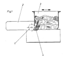
- the device shown only schematically in FIG. 1 comprises a rotor 1 designed as a solid shaft rotor, which is mounted in a fixed position in a machine stand 2 and to which the material to be shredded is fed via a horizontally displaceable hopper 3, the rear wall of which is the material to be shredded against the rotor 1 presses.
- the rotor 1 is associated with a fixedly arranged and comb-like shear bar 4, which is shown in FIGS. 2 and 3 on an enlarged scale.
- This shear bar 4 is arranged as close as possible to the rotor 1, so that only a narrow air gap a remains between the shear bar 4 and the outer surface of the rotor 1 (see FIG. 3).
- the bed knife 4 forms an angle ⁇ ⁇ 90 ° with the leading lateral surface of the rotor 1 (see FIG. 2).
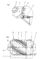
- the outer surface of the drivable rotor 1 is equipped with cutting bodies 5 which are each arranged in the form of a helix 12 according to FIG. 3.
- Each cutting body 5 is fastened in a groove 9 assigned only to it, which is V-shaped and as a secant is formed and has an opening angle ⁇ of 90 ° (see Figure 4).
- each cutting body 5 is designed as a square cutting plate, which is supported in the assembled position with its lower half on the two flanks of the groove 9 and, with its upper, triangular half, forms the section that is effective for comminution.
- FIG. 4 shows that the cutting bodies 5 lying next to one another in the axial direction are arranged with an overcut.
- grooves 9 lie in mutually parallel planes which are perpendicular to the rotor axis 10, and that the circumferential surface of the rotor 1 between these grooves 9 has a smooth surface as seen in the circumferential direction.
- the counter cutting edge 4 engages like a comb between the rotating cutting bodies 5 (see FIG. 3).
- each cutting body 5 lies against a cutting body carrier 6 and is screwed to the latter by means of a screw 7 shown as an Allen screw (see FIG. 5).
- the cutting body carrier 6 is welded to the rotor 1.
- FIGS. 4 and 5 in particular show that each cutting body 5 can be rotated by 90 ° about its central turning axis 11 after it has been removed or before it is installed, and can therefore be used four times.
- the rotor 1 is equipped at both of its axial ends lying outside the working area of the cutting body 5 with a broaching body 8, the flight circle of which is somewhat smaller than that of the cutting body 5, and the shape of which corresponds to that of the cutting body 5.
- These clearing bodies 8 clear the inner area next to the side walls of the funnel 3 and thereby prevent material jamming in this area.
Description
Die Erfindung betrifft eine Vorrichtung zum Zerkleinern von Rest- und Abfallhölzern, Rinden, Kunststoffen, Kartonagen o. dgl. mit einem antreibbaren zylindrischen Rotor, dessen Mantelfläche mit Schneidkörpern bestückt ist, die jeweils in einer nur einem Schneidkörper zugeordneten Nut befestigt sind, wobei diese Nuten in zueinander jeweils parallelen, senkrecht auf der Rotorachse stehenden Ebenen liegen,
zwischen den Nuten die Mantelfläche des Rotors in Umfangsrichtung glattflächig ausgebildet ist, und
eine ortsfest angeordnete Gegenschneide kammartig zwischen die umlaufenden Schneidkörper eingreift.The invention relates to a device for shredding residual and waste wood, bark, plastics, cardboard or the like. With a drivable cylindrical rotor, the outer surface of which is equipped with cutting bodies, each of which is fastened in a groove assigned to only one cutting body, these grooves lie in mutually parallel planes perpendicular to the rotor axis,
between the grooves, the circumferential surface of the rotor is smooth in the circumferential direction, and
a fixed counter blade engages like a comb between the rotating cutting bodies.
Eine derartige, dem ersten Teil des Anspruchs 1 entsprechende Ausführungsform läßt sich der DE-A-29 43 567 entnehmen. Es handelt sich hier um eine Reißwalzenzerkleinerungsmaschine mit einer Reißzahnwalze, deren einzelnen Reißzähne mit jeweils einem zylindrischen oder kegelförmigen Schaft in entsprechend angepaßte Radialbohrungen im Walzenkörper eingesetzt sind und dabei in im Querschnitt angenähert rechteckig ausgebildete Nuten eintauchen, die eine Verdrehsicherung darstellen. Die Reißzähne kämmen mit einer oder mehreren feststehenden Reißzahnreihen. Jeder Reißzahn ist mit einer in Stirnansicht flach rechteckig ausgebildeten Hartmetallschneide bestückt, die vollständig radial außerhalb der dem Reißzahn zugeordneten Nut und in ihrer länglichen Ausdehnung angenähert parallel zur Rotorachse liegt. Der Abstand der Gegenschneiden von der Mantelfläche des Rotors ist so groß, daß der Flugkreis von zusätzlich zu den Reißzähnen in der Reißzahnwalze angeordneten Grundschneiden noch außerhalb der Gegenschneiden liegt.Such an embodiment, corresponding to the first part of
Die DE-A-27 02 177 offenbart eine Walzenzerkleinerungsmaschine mit mindestens einem gegenläufigen Walzenpaar, dessen Walzen mit Reißzähnen bestückt sind, die in einer Schraubenlinie angeordnet sind. Der Zerkleinerungsvorgang erfolgt durch Reißen und zwar aufgrund der Differenzdrehzahl der miteinander kämmenden Reißzähne.DE-A-27 02 177 discloses a roller comminution machine with at least one counter-rotating pair of rollers, the rollers of which are equipped with fangs, which are arranged in a helical line. The crushing process is carried out by tearing, specifically because of the differential speed of the intermeshing fangs.
Durch offenkundige Vorbenutzung ist ferner bekannt geworden eine Vorrichtung zum Zerkleinern von Rest- und Abfallhölzern, Rinden, Kunststoffen, Kartonagen o. dgl. mit einem antreibbaren zylindrischen Rotor, dessen Mantelfläche mit Schneidkörpern bestückt ist, die in im Querschnitt V-förmig ausgebildeten Nuten befestigt sind. Derartige Vorrichtungen werden eingesetzt zur Herstellung von Granulat, das einer Verbrennung, Deponierung oder einem Recycling zugeführt wird. Bei dieser vorbekannten Ausführungsform sind die genannten Nuten spiralförmig in die Mantelfläche des Rotors eingedreht und führen dadurch während des Zerkleinerungsvorganges zu Verklemmungen durch Zerkleinerungsmaterial, das zwischen Rotor und Gegenschneide eingeklemmt wird.A device for shredding residual and waste wood, bark, plastics, cardboard or the like has also become known from prior public use with a drivable cylindrical rotor, the outer surface of which is equipped with cutting bodies which are fastened in cross-sectionally V-shaped grooves . Devices of this type are used for the production of granules which are fed to incineration, landfill or recycling. In the case of this known embodiment, the grooves mentioned are screwed into the outer surface of the rotor in a spiral and thus lead to jamming during the comminution process by comminution material which is clamped between the rotor and the shear bar.
Die DE-A-23 32 060 offenbart einen Vorzerkleinerer für Stanzgitterabfälle. Die Vorrichtung umfaßt eine Walze, die auf ihrer Mantelfläche mit versetzt angeordneten Dreiecksmessern bestückt ist, die in axial verlaufenden Nuten sitzen und an einer Messerstütze befestigt sind. Über die axiale Länge der Walze verlaufen schraubenförmige Leitflächen, die im Bereich der Messer ihre radial niedrigste und in axialer Richtung gesehen zwischen den Messern ihre größte radiale Höhe aufweisen.DE-A-23 32 060 discloses a pre-shredder for leadframe waste. The device comprises a roller which is equipped on its outer surface with staggered triangular knives, which sit in axially extending grooves and are fastened to a knife support. Helical guide surfaces run over the axial length of the roller and have their radially lowest in the area of the knives and their greatest radial height between the knives as seen in the axial direction.
Die US-A-3 202 369 offenbart eine Vorrichtung zum Zerreißen von Blech. Auf der Mantelfläche eines Rotors sind Schneidkörper angeordnet, die an der Stirnfläche eines Halters oberhalb der genannten Mantelfläche befestigt sind und die Form eines gleichseitigen Dreiecks aufweisen.US-A-3 202 369 discloses an apparatus for tearing sheet metal. On the outer surface of a rotor, cutting bodies are arranged, which are fastened to the end face of a holder above said outer surface and have the shape of an equilateral triangle.
Der Erfindung liegt die Aufgabe zugrunde, die eingangs beschriebene Vorrichtung hinsichtlich ihrer Leistung zu verbessern.The invention has for its object to improve the performance of the device described above.
Diese Aufgabe wird gemäß der Erfindung durch folgende Merkmale gelöst:
- a) die Schneidkörper sind auf der Mantefläche des Rotors in zumindest einer Schraubenlinie angeordnet;
- b) jede Nut ist im Querschnitt V-förmig ausgebildet;
- c) der wirksame Abschnitt jedes Schneidkörpers ist in Umlaufrichtung gesehen angenähert dreiecksförmig ausgebildet;
- d) jeder Schneidkörper ist quadratisch ausgebildet und um eine zentrische Wendeachse um jeweils 90° verdrehbar;
- e) zwischen Gegenschneide und Mantelfläche des Rotors verbleibt nur ein enger Luftspalt.
- a) the cutting bodies are arranged on the surface of the rotor in at least one helix;
- b) each groove is V-shaped in cross section;
- c) the effective section of each cutting body is approximately triangular in shape in the circumferential direction;
- d) each cutting body is square and can be rotated by 90 ° about a central turning axis;
- e) only a narrow air gap remains between the shear bar and the outer surface of the rotor.
Zwar läßt sich durch die glattflächige Ausbildung der Rotor-Mantelfläche zwischen den Nuten eine Verklemmung von Zerkleinerungsmaterial zwischen Rotor und Gegenschneide bereits weitgehend verhindern; jedoch lassen sich diese Verklemmungen erfindungsgemäß dadurch auf ein Minimum reduzieren, daß das Gegenmesser bis dicht an die Mantelfläche des Rotors ragt. Diese vorteilhafte Wirkung läßt sich zusätzlich noch dadurch erhöhen, daß die Gegenschneide mit der vorlaufenden Mantelfläche des Rotors einen Winkel < 90° einschließt. Aufgrund dieser Anordnung wird die Selbsteinzugswirkung wesentlich verringert.A jamming of the crushing material between the rotor and the shear bar can already be largely prevented by the smooth surface design of the rotor jacket surface between the grooves; however, according to the invention, these jams can be reduced to a minimum by the counter knife projecting close to the outer surface of the rotor. This advantageous effect can be further increased if the shear bar forms an angle of <90 ° with the leading lateral surface of the rotor. Due to this arrangement, the self-retracting effect is significantly reduced.
Um die Schneidkraft möglichst gering zu halten, ist der wirksame Abschnitt jedes Schneidkörpers in Umlaufrichtung gesehen angenähert dreiecksfömig ausgebildet. Um den Schneidkörper vierfach verwenden zu können, ist er quadratisch ausgebildet und um jeweils 90° verdrehbar.In order to keep the cutting force as low as possible, the effective section of each cutting body is approximately triangular in shape in the direction of rotation. In order to be able to use the cutting body four times, it is square and rotatable by 90 °.
In einer zweckmäßigen Ausführungsform ist vorgesehen, daß die V-förmige Nut einen Öffnungswinkel (α) von 90° aufweist und daß sich jeder Schneidkörper in seiner montierten Stellung an den beiden Nutflanken abstützt. Durch diese Einbettung des Schneidkörpers in die ihm zugeordnete Nut ist die Lage jedes Schneidkörpers jeweils eindeutig fixiert.In an expedient embodiment it is provided that the V-shaped groove has an opening angle (α) of 90 ° and that each cutting body is supported on the two groove flanks in its assembled position. By embedding the cutting body in the groove assigned to it, the position of each cutting body is clearly fixed in each case.
Um Verklemmungen des Zerkleinerungsmaterials im Bereich der Seitenwände eines Zuführtrichters o. dgl. zu vermeiden, ist es vorteilhaft, wenn der Rotor an seinen beiden außerhalb des Arbeitsbereiches der Schneidkörper liegenden axialen Enden mit zumindest je einem Räumkörper bestückt ist, dessen Flugkreis etwas kleiner ist als der der Schneidkörper.In order to avoid jamming of the comminution material in the area of the side walls of a feed hopper or the like, it is advantageous if the rotor at both of its axial ends lying outside the working area of the cutting body is equipped with at least one clearing body, the flight circle of which is somewhat smaller than that the cutting body.
Der Rotor kann vorzugsweise als Vollwellenrotor ausgebildet sein. Es reicht grundsätzlich aus, die Schneidkörper in nur einer einzigen Schraubenlinie auf der Rotormantelfläche anzuordnen. Zur Erhöhung der Leistung sowie zur Abstufung der Granulatgröße können aber auch mehrere Schneidkörper-Schraubenlinien vorgesehen werden.The rotor can preferably be designed as a solid shaft rotor. It is basically sufficient to arrange the cutting bodies in a single helical line on the surface of the rotor. In order to increase the performance and to gradate the granulate size, several cutting element screw lines can also be provided.
Die in Axialrichtung gesehen jeweils nebeneinander liegenden Schneidkörper können mit Überschnitt angeordnet sein. An diesen Überschnitt ist der Abstand der Gegenschneide vom Rotormantel anzupassen.The cutting bodies lying side by side in the axial direction can be arranged with an overcut. The distance between the shear bar and the rotor jacket must be adjusted to this overlap.
Durch die erfindungsgemäß empfohlenen Maßnahmen lassen sich die Belastungsspitzen, die Leistungsaufnahme sowie Stillstandszeiten durch Materialverklemmungen verringern und das Zerspanungsverhalten verbessern.The measures recommended according to the invention reduce the peak loads, the power consumption and downtimes due to material jams and improve the cutting behavior.
Weiterhin ist es zweckmäßig, wenn auf der Rotor-Mantelfläche zumindest zwei Schneidkörper-Schraubenlinien vorgesehen sind, die um 180° gegeneinander versetzt sind, sich jeweils nur um etwa den halben Rotorumfang und jeweils nur über etwa eine halbe Rotorlänge erstrecken und dem zerkleinerten Material jeweils einen einander axial zur Rotormitte entgegengerichteten Drall verleihen. Durch diese weitergehende Ausbildung einer Vorrichtung ergibt sich eine Konzentration des Zerkleinerungsmaterials in Richtung zum mittleren Abschnitt des Rotors. Dadurch wird der Vorteil erzielt, daß sich das Zerkleinerungsmaterial zwischen dem insbesondere als Vollwellenrotor ausgebildeten Rotor und der Gegenschneide bzw. einem eingeschalteten Sieb nicht einseitig verdichtet.Furthermore, it is expedient if at least two cutting-body helix lines are provided on the outer surface of the rotor, which are offset by 180 ° with respect to one another, in each case only about half the rotor circumference and in each case only over about half Extend rotor length and each give the shredded material an opposite twist axially to the center of the rotor. This further development of a device results in a concentration of the comminution material in the direction of the central section of the rotor. This has the advantage that the shredding material is not compacted on one side between the rotor, which is designed in particular as a solid shaft rotor, and the shear bar or a switched-on sieve.
Weitere Merkmale der Erfindung sind Gegenstand der Unteransprüche und werden in Verbindung mit weiteren Vorteilen der Erfindung anhand eines Bauausführungsbeispieles näher erläutert.Further features of the invention are the subject of the subclaims and are explained in more detail in connection with further advantages of the invention using a construction example.
In der Zeichnung ist eine als Beispiel dienende Ausführungsform der Erfindung dargestellt. Es zeigen:
- Figur 1 -
- in schematischer Darstellung in Seitenansicht und zum Teil im Längsschnitt eine Zerkleinerungsvorrichtung;
- Figur 2 -
- in vergrößertem Maßstab ein Detail der
Figur 1; - Figur 3 -
- die Darstellung gemäß
Figur 2 in Stirnansicht; - Figur 4 -
- ein Detail der
Figur 3 in vergrößertem Maßstab und - Figur 5 -
- einen Schnitt gemäß der Linie A-B in
Figur 4.
- Figure 1 -
- in a schematic representation in side view and partly in longitudinal section a shredding device;
- Figure 2 -
- on an enlarged scale a detail of Figure 1;
- Figure 3 -
- the representation of Figure 2 in front view;
- Figure 4 -
- a detail of Figure 3 on an enlarged scale and
- Figure 5 -
- a section along the line AB in Figure 4.
Die in Figur 1 nur schematisch dargestellte Vorrichtung umfaßt einen als Vollwellenrotor ausgebildeten Rotor 1, der ortsfest in einem Maschinenständer 2 gelagert ist, und dem das zu zerkleinernde Material über einen horizontal verschiebbaren Trichter 3 zugeführt wird, dessen Rückwand das zu zerkleinernde Material gegen den Rotor 1 drückt. Dem Rotor 1 ist eine ortsfest angeordnete und kammartig ausgebildete Gegenschneide 4 zugeordnet, die in den Figuren 2 und 3 in vergrößertem Maßstab dargestellt ist. Diese Gegenschneide 4 ist möglichst dicht am Rotor 1 angeordnet, so daß zwischen Gegenschneide 4 und Mantelfläche des Rotors 1 nur ein enger Luftspalt a verbleibt (siehe Figur 3). Außerdem schließt die Gegenschneide 4 mit der vorlaufenden Mantelfläche des Rotors 1 einen Winkel β < 90° ein (siehe Figur 2).The device shown only schematically in FIG. 1 comprises a
Die Mantelfläche des antreibbaren Rotors 1 ist mit Schneidkörpern 5 bestückt, die gemäß Figur 3 jeweils in Form einer Schraubenlinie 12 angeordnet sind. Jeder Schneidkörper 5 ist in einer nur ihm zugeordneten Nut 9 befestigt, die V-förmig sowie als Sekante ausgebildet ist und einen Öffnungswinkel α von 90° aufweist (siehe Figur 4). Jeder Schneidkörper 5 ist von vorn gesehen als quadratische Schneidplatte ausgebildet, die sich in montierter Stellung mit ihrer unteren Hälfte an den beiden Flanken der Nut 9 abstützt und mit ihrer jeweils oberen, dreiecksförmigen Hälfte den für die Zerkleinerung wirksamen Abschnitt bildet. Figur 4 läßt erkennen, daß die in axialer Richtung gesehen nebeneinander liegenden Schneidkörper 5 mit Überschnitt angeordnet sind. Figur 3 macht ferner deutlich, daß die Nuten 9 in zueinander jeweils parallelen, senkrecht auf der Rotorachse 10 stehenden Ebenen liegen, und daß die Mantelfläche des Rotors 1 zwischen diesen Nuten 9 in Umfangsrichtung gesehen glattflächig ausgebildet ist. Die Gegenschneide 4 greift kammartig zwischen die umlaufenden Schneidkörper 5 ein (siehe Figur 3).The outer surface of the
Jeder Schneidkörper 5 liegt mit seiner Rückseite an einem Schneidkörperträger 6 an und ist mit diesem über eine als Inbusschraube dargestellte Schraube 7 verschraubt (siehe Figur 5). Der Schneidkörperträger 6 ist mit dem Rotor 1 verschweißt.The back of each cutting
Insbesondere die Figuren 4 und 5 lassen erkennen, daß jeder Schneidkörper 5 nach seinem Ausbau bzw. vor seinem Einbau um jeweils 90° um seine zentrische Wendeachse 11 verdrehbar ist und dadurch vierfach verwendet werden kann.FIGS. 4 and 5 in particular show that each cutting
Gemäß Figur 3 ist der Rotor 1 an seinen beiden außerhalb des Arbeitsbereiches der Schneidkörper 5 liegenden axialen Enden mit je einem Räumkörper 8 bestückt, dessen Flugkreis etwas kleiner ist als der der Schneidkörper 5, und dessen Form der der Schneidkörper 5 entspricht. Diese Räumkörper 8 räumen den inneren Bereich neben den Seitenwänden des Trichters 3 frei und verhindern dadurch in diesem Bereich eine Materialverklemmung.According to FIG. 3, the
Claims (10)
- Apparatus for the shredding of scrap and waste wood, bark, plastics, cardboard packaging and the like using a drivable cylindrical rotor (1), whose outer surface is equipped with cutter bodies (5) each of which is fixed in a groove (9) which is assigned to only one cutter body (5), these grooves (9) lying in planes which are parallel to each other in each case and perpendicular to the rotor axis (10),
the outer surface of the rotor (1) between the grooves (9) being constructed to have a smooth face in the peripheral direction, and a counter-cutting edge (4) which is fixed in place meshing between the rotating cutters (5) like a comb, characterised by the following features:a) the cutter bodies (5) are arranged in at least one helical line (23) on the outer surface of the rotor (1);b) each groove (9) is constructed to have a V-shaped cross-section;c) the effective segment of each cutter body (5) is constructed to be approximately triangular when viewed in the direction of rotation;d) each cutter body (5) is constructed to be square and is rotatable by 90° each about a central turning axis (11);e) there is only a narrow air gap (a) between the counter-cutting edge (4) and the outer surface of the rotor (1). - Apparatus according to Claim 1, characterised in that the V-shaped groove (9) has an aperture angle (α) of 90° and that each cutter body (5), when installed, is supported by the two sides of the groove.
- Apparatus according to Claim 1 or 2, characterised in that the reverse side of each cutter body (5) bears against a cutter body carrier (6) and the cutter body is screwed thereto.
- Apparatus according to Claim 3, characterised in that the cutter body carrier (6) is welded to the rotor (1).
- Apparatus according to one of the preceding claims, characterised in that the cutter bodies (5) overlap when viewed axially.
- Apparatus according to one of the preceding claims, characterised in that the rotor (1) is fitted with at least one clearer body (8) at each of its two axial ends lying outside the working area of the cutter bodies (5), the circular orbit of this clearer body being somewhat smaller than that of the cutter bodies (5).
- Apparatus according to Claim 6, characterised in that the clearer bodies (8) have the same shape as the cutter bodies (5).
- Apparatus according to one of the preceding claims, characterised in that each groove (9) is constructed as a secant.
- Apparatus according to one of the preceding claims, characterised in that the counter-cutting edge (4) makes an angle of (β) ≦ 90° with the leading outer surface of the rotor (1).
- Apparatus according to one of the preceding claims, characterised in that at least two cutter body/helical lines (12), which are displaced by 180° from each other, are provided on the outer surface of the rotor, each of which extends over only approximately half the circumference of the rotor and each of which extends over only approximately half the length of the rotor and which each give to the shredded material a spin which is directed axially away with respect to each other from the centre of the rotor.
Priority Applications (1)
| Application Number | Priority Date | Filing Date | Title |
|---|---|---|---|
| AT90104879T ATE89193T1 (en) | 1989-03-15 | 1990-03-15 | DEVICE FOR SHREDDING WASTE WOOD AND WASTE. |
Applications Claiming Priority (4)
| Application Number | Priority Date | Filing Date | Title |
|---|---|---|---|
| DE19893908395 DE3908395C2 (en) | 1989-03-15 | 1989-03-15 | Device for shredding residual and waste wood |
| DE3908395 | 1989-03-15 | ||
| DE3938820A DE3938820A1 (en) | 1989-03-15 | 1989-11-23 | DEVICE FOR CRUSHING RESIDUAL AND WASTE WOODS |
| DE3938820 | 1989-11-23 |
Publications (3)
| Publication Number | Publication Date |
|---|---|
| EP0387868A2 EP0387868A2 (en) | 1990-09-19 |
| EP0387868A3 EP0387868A3 (en) | 1991-01-30 |
| EP0387868B1 true EP0387868B1 (en) | 1993-05-12 |
Family
ID=25878821
Family Applications (1)
| Application Number | Title | Priority Date | Filing Date |
|---|---|---|---|
| EP90104879A Expired - Lifetime EP0387868B1 (en) | 1989-03-15 | 1990-03-15 | Shredding apparatus for waste wood |
Country Status (2)
| Country | Link |
|---|---|
| EP (1) | EP0387868B1 (en) |
| DE (2) | DE3938820A1 (en) |
Families Citing this family (13)
| Publication number | Priority date | Publication date | Assignee | Title |
|---|---|---|---|---|
| DE4200796A1 (en) * | 1992-01-15 | 1993-05-27 | Dieter Knauss | WOOD SHREDDING DEVICE AND KNIFE ELEMENT FOR A WOOD SHREDDING DEVICE |
| AT399670B (en) * | 1992-11-04 | 1995-06-26 | Lindner Ges M B H Maschf | Device for the comminution of waste materials |
| DE4242740C2 (en) * | 1992-12-17 | 1998-09-10 | Holz Metall Abfall Recyclingte | Shredding machine |
| CN1134144A (en) * | 1993-10-20 | 1996-10-23 | 宇宙绿化有限公司 | Composting apparatus |
| DE29504464U1 (en) * | 1995-03-16 | 1995-05-11 | Gres Holzaufbereitungs Gmbh | Plant for processing wood, especially waste wood |
| DE29515768U1 (en) * | 1995-10-04 | 1995-12-07 | Holz Metall Abfall Recyclingte | Cutting tool for shredding machines |
| EP0908238A1 (en) | 1997-10-06 | 1999-04-14 | UNTERWURZACHER PATENTVERWERTUNGSGESELLSCHAFT mbH | Material shredding apparatus |
| AT406354B (en) * | 1998-07-20 | 2000-04-25 | Wilhelm Bluemlinger | CRUSHING DEVICE |
| FR2785205B1 (en) | 1998-10-30 | 2001-01-26 | Phenix Ind | WASTE GRINDING DEVICE |
| FR2785202B1 (en) * | 1999-05-19 | 2000-12-01 | Guy Auguste Emile Sosson | MACHINE FOR SHREDDING BULKY OBJECTS |
| IT1396480B1 (en) | 2009-10-23 | 2012-12-14 | C M G S P A | PERFECTING IN MACHINES TO GRIND VARIOUS MATERIALS LIKE PLASTIC BLOCKS, WOOD RESIDUES, CARTONAGE AND SO VIA. |
| CN103480469A (en) * | 2013-09-02 | 2014-01-01 | 胡必胜 | Crushing rolling wheel for plastic chips |
| CN111841817B (en) * | 2020-07-23 | 2021-09-21 | 苏州贝基电子科技有限公司 | Purple sand raw ore material processing system and processing method |
Citations (2)
| Publication number | Priority date | Publication date | Assignee | Title |
|---|---|---|---|---|
| DE2702177A1 (en) * | 1977-01-20 | 1978-07-27 | Kloeckner Gmbh & Co Geb | Waste material pulverising rollers - rotating in opposite directions at different speeds and having hard metal tipped teeth |
| DE2943567A1 (en) * | 1979-10-29 | 1981-04-30 | Peter 5439 Bretthausen Voelskow | Fragmenting machine which works by tearing - has cylinder with helically set square cross=section teeth on cylindrical stubs fitted radially |
Family Cites Families (2)
| Publication number | Priority date | Publication date | Assignee | Title |
|---|---|---|---|---|
| US3216470A (en) * | 1962-07-09 | 1965-11-09 | Soderhamns Verkst Er Ab | Method and a machine for producing wood particles |
| US3202369A (en) * | 1963-01-16 | 1965-08-24 | Steel Briquette Corp | Rotary sheet metal tearing devices |
-
1989
- 1989-11-23 DE DE3938820A patent/DE3938820A1/en not_active Ceased
-
1990
- 1990-03-15 DE DE9090104879T patent/DE59001396D1/en not_active Expired - Fee Related
- 1990-03-15 EP EP90104879A patent/EP0387868B1/en not_active Expired - Lifetime
Patent Citations (2)
| Publication number | Priority date | Publication date | Assignee | Title |
|---|---|---|---|---|
| DE2702177A1 (en) * | 1977-01-20 | 1978-07-27 | Kloeckner Gmbh & Co Geb | Waste material pulverising rollers - rotating in opposite directions at different speeds and having hard metal tipped teeth |
| DE2943567A1 (en) * | 1979-10-29 | 1981-04-30 | Peter 5439 Bretthausen Voelskow | Fragmenting machine which works by tearing - has cylinder with helically set square cross=section teeth on cylindrical stubs fitted radially |
Also Published As
| Publication number | Publication date |
|---|---|
| DE59001396D1 (en) | 1993-06-17 |
| EP0387868A2 (en) | 1990-09-19 |
| DE3938820A1 (en) | 1991-05-29 |
| EP0387868A3 (en) | 1991-01-30 |
Similar Documents
| Publication | Publication Date | Title |
|---|---|---|
| EP1731223B1 (en) | Comminutor | |
| EP2679309B1 (en) | Crushing device comprising a crushing rotor with continuous cutting edge | |
| EP0387868B1 (en) | Shredding apparatus for waste wood | |
| EP0529221B1 (en) | Comminuting device | |
| EP2218507A2 (en) | Device for grinding dispensed products with stripping elements | |
| DE102009060523A1 (en) | Crushing device with counter knife device | |
| DE3112639C2 (en) | ||
| DE2256524A1 (en) | PROCESS AND DEVICE FOR CRUSHING GOOD IN SMALL PIECES | |
| DE2516111C2 (en) | Shredding device, in particular for processing paper and plastic material | |
| DE2256267C3 (en) | Shredder working with shear action | |
| EP1497032B1 (en) | Crushing device | |
| EP1237656A1 (en) | Device for comminuting a good to be comminuted | |
| DE2164566A1 (en) | SHREDDING UNIT | |
| EP0124138B1 (en) | Method and apparatus for grinding vegetal products | |
| DE2502665A1 (en) | WASTE SHREDDING DEVICE | |
| DE3908395C2 (en) | Device for shredding residual and waste wood | |
| DE102019108306A1 (en) | Cutting mill for cutting samples | |
| DE2943567A1 (en) | Fragmenting machine which works by tearing - has cylinder with helically set square cross=section teeth on cylindrical stubs fitted radially | |
| AT395838B (en) | KNIFE ROLLER FOR A DEVICE FOR PRE-MILLING FREEZED GOODS | |
| DE10113953C1 (en) | Device for shredding plastic structures with a low material thickness | |
| DE3827767C2 (en) | ||
| EP2549892B1 (en) | Blade box for disintegrating device for organic matter | |
| EP0847805A1 (en) | Cutting tool for screw conveyor device | |
| DE7818838U1 (en) | MACHINE FOR CRUSHING WASTE MATERIALS | |
| DE2531288C2 (en) | Device for grinding a granular food grist |
Legal Events
| Date | Code | Title | Description |
|---|---|---|---|
| PUAI | Public reference made under article 153(3) epc to a published international application that has entered the european phase |
Free format text: ORIGINAL CODE: 0009012 |
|
| AK | Designated contracting states |
Kind code of ref document: A2 Designated state(s): AT CH DE FR IT LI |
|
| ITCL | It: translation for ep claims filed |
Representative=s name: MODIANO & ASSOCIATI S.R.L. |
|
| EL | Fr: translation of claims filed | ||
| PUAL | Search report despatched |
Free format text: ORIGINAL CODE: 0009013 |
|
| AK | Designated contracting states |
Kind code of ref document: A3 Designated state(s): AT CH DE FR IT LI |
|
| 17P | Request for examination filed |
Effective date: 19910220 |
|
| 17Q | First examination report despatched |
Effective date: 19920311 |
|
| GRAA | (expected) grant |
Free format text: ORIGINAL CODE: 0009210 |
|
| RAP1 | Party data changed (applicant data changed or rights of an application transferred) |
Owner name: KLOECKNER MASCHINEN- UND ANLAGENBAU GMBH |
|
| AK | Designated contracting states |
Kind code of ref document: B1 Designated state(s): AT CH DE FR IT LI |
|
| REF | Corresponds to: |
Ref document number: 89193 Country of ref document: AT Date of ref document: 19930515 Kind code of ref document: T |
|
| REF | Corresponds to: |
Ref document number: 59001396 Country of ref document: DE Date of ref document: 19930617 |
|
| ET | Fr: translation filed | ||
| ITF | It: translation for a ep patent filed |
Owner name: MODIANO & ASSOCIATI S.R.L. |
|
| ITPR | It: changes in ownership of a european patent |
Owner name: CAMBIO RAGIONE SOCIALE;BMH WOOD TECHNOLOGY GMBH |
|
| REG | Reference to a national code |
Ref country code: CH Ref legal event code: PFA Free format text: BMH WOOD TECHNOLOGY GMBH |
|
| REG | Reference to a national code |
Ref country code: FR Ref legal event code: CD |
|
| PGFP | Annual fee paid to national office [announced via postgrant information from national office to epo] |
Ref country code: AT Payment date: 19960311 Year of fee payment: 7 |
|
| PGFP | Annual fee paid to national office [announced via postgrant information from national office to epo] |
Ref country code: FR Payment date: 19960313 Year of fee payment: 7 |
|
| PGFP | Annual fee paid to national office [announced via postgrant information from national office to epo] |
Ref country code: CH Payment date: 19960328 Year of fee payment: 7 |
|
| PG25 | Lapsed in a contracting state [announced via postgrant information from national office to epo] |
Ref country code: AT Effective date: 19970315 |
|
| PG25 | Lapsed in a contracting state [announced via postgrant information from national office to epo] |
Ref country code: LI Effective date: 19970331 Ref country code: CH Effective date: 19970331 |
|
| REG | Reference to a national code |
Ref country code: CH Ref legal event code: PL |
|
| PG25 | Lapsed in a contracting state [announced via postgrant information from national office to epo] |
Ref country code: FR Free format text: LAPSE BECAUSE OF NON-PAYMENT OF DUE FEES Effective date: 19971128 |
|
| REG | Reference to a national code |
Ref country code: FR Ref legal event code: ST |
|
| PGFP | Annual fee paid to national office [announced via postgrant information from national office to epo] |
Ref country code: DE Payment date: 20010303 Year of fee payment: 12 |
|
| PG25 | Lapsed in a contracting state [announced via postgrant information from national office to epo] |
Ref country code: DE Free format text: LAPSE BECAUSE OF NON-PAYMENT OF DUE FEES Effective date: 20021001 |
|
| PG25 | Lapsed in a contracting state [announced via postgrant information from national office to epo] |
Ref country code: IT Free format text: LAPSE BECAUSE OF NON-PAYMENT OF DUE FEES;WARNING: LAPSES OF ITALIAN PATENTS WITH EFFECTIVE DATE BEFORE 2007 MAY HAVE OCCURRED AT ANY TIME BEFORE 2007. THE CORRECT EFFECTIVE DATE MAY BE DIFFERENT FROM THE ONE RECORDED. Effective date: 20050315 |
|
| PLBE | No opposition filed within time limit |
Free format text: ORIGINAL CODE: 0009261 |
|
| STAA | Information on the status of an ep patent application or granted ep patent |
Free format text: STATUS: NO OPPOSITION FILED WITHIN TIME LIMIT |