EP0387868B1 - Dispositif de broyage pour déchets de bois - Google Patents
Dispositif de broyage pour déchets de bois Download PDFInfo
- Publication number
- EP0387868B1 EP0387868B1 EP90104879A EP90104879A EP0387868B1 EP 0387868 B1 EP0387868 B1 EP 0387868B1 EP 90104879 A EP90104879 A EP 90104879A EP 90104879 A EP90104879 A EP 90104879A EP 0387868 B1 EP0387868 B1 EP 0387868B1
- Authority
- EP
- European Patent Office
- Prior art keywords
- rotor
- cutter
- cutter body
- bodies
- groove
- Prior art date
- Legal status (The legal status is an assumption and is not a legal conclusion. Google has not performed a legal analysis and makes no representation as to the accuracy of the status listed.)
- Expired - Lifetime
Links
- 239000002699 waste material Substances 0.000 title claims description 5
- 239000002023 wood Substances 0.000 title claims description 4
- 239000000463 material Substances 0.000 claims description 11
- -1 bark Substances 0.000 claims description 3
- 239000004033 plastic Substances 0.000 claims description 3
- 229920003023 plastic Polymers 0.000 claims description 3
- 238000004806 packaging method and process Methods 0.000 claims 1
- 230000002093 peripheral effect Effects 0.000 claims 1
- 239000007787 solid Substances 0.000 description 3
- 230000000694 effects Effects 0.000 description 2
- 239000008187 granular material Substances 0.000 description 2
- 239000002184 metal Substances 0.000 description 2
- 238000000034 method Methods 0.000 description 2
- 230000004323 axial length Effects 0.000 description 1
- 238000010276 construction Methods 0.000 description 1
- 230000018109 developmental process Effects 0.000 description 1
- 238000004519 manufacturing process Methods 0.000 description 1
- 238000004064 recycling Methods 0.000 description 1
Images

Classifications
-
- B—PERFORMING OPERATIONS; TRANSPORTING
- B02—CRUSHING, PULVERISING, OR DISINTEGRATING; PREPARATORY TREATMENT OF GRAIN FOR MILLING
- B02C—CRUSHING, PULVERISING, OR DISINTEGRATING IN GENERAL; MILLING GRAIN
- B02C18/00—Disintegrating by knives or other cutting or tearing members which chop material into fragments
- B02C18/0084—Disintegrating by knives or other cutting or tearing members which chop material into fragments specially adapted for disintegrating garbage, waste or sewage
-
- B—PERFORMING OPERATIONS; TRANSPORTING
- B02—CRUSHING, PULVERISING, OR DISINTEGRATING; PREPARATORY TREATMENT OF GRAIN FOR MILLING
- B02C—CRUSHING, PULVERISING, OR DISINTEGRATING IN GENERAL; MILLING GRAIN
- B02C18/00—Disintegrating by knives or other cutting or tearing members which chop material into fragments
- B02C18/06—Disintegrating by knives or other cutting or tearing members which chop material into fragments with rotating knives
- B02C18/14—Disintegrating by knives or other cutting or tearing members which chop material into fragments with rotating knives within horizontal containers
- B02C18/145—Disintegrating by knives or other cutting or tearing members which chop material into fragments with rotating knives within horizontal containers with knives spaced axially and circumferentially on the periphery of a cylindrical rotor unit
Definitions
- the invention relates to a device for shredding residual and waste wood, bark, plastics, cardboard or the like.
- a drivable cylindrical rotor the outer surface of which is equipped with cutting bodies, each of which is fastened in a groove assigned to only one cutting body, these grooves lie in mutually parallel planes perpendicular to the rotor axis, between the grooves, the circumferential surface of the rotor is smooth in the circumferential direction, and a fixed counter blade engages like a comb between the rotating cutting bodies.
- Such an embodiment corresponding to the first part of claim 1, can be found in DE-A-29 43 567. It is a shredding roller comminution machine with a serration roller, the individual serration teeth, each with a cylindrical or conical shaft, are inserted into correspondingly adapted radial bores in the roller body and are immersed in grooves which are approximately rectangular in cross section and which prevent rotation.
- the fangs mesh with one or more rows of fixed fangs.
- Each fang is with a flat rectangular hard metal cutting edge in front view equipped, which is completely radially outside the groove assigned to the fang and in its elongated extent approximately parallel to the rotor axis. The distance between the counter cutting edges and the outer surface of the rotor is so large that the flight circle of basic cutting edges arranged in addition to the fangs in the furrow roller is still outside the counter cutting edges.
- DE-A-27 02 177 discloses a roller comminution machine with at least one counter-rotating pair of rollers, the rollers of which are equipped with fangs, which are arranged in a helical line.
- the crushing process is carried out by tearing, specifically because of the differential speed of the intermeshing fangs.
- a device for shredding residual and waste wood, bark, plastics, cardboard or the like has also become known from prior public use with a drivable cylindrical rotor, the outer surface of which is equipped with cutting bodies which are fastened in cross-sectionally V-shaped grooves .
- Devices of this type are used for the production of granules which are fed to incineration, landfill or recycling.
- the grooves mentioned are screwed into the outer surface of the rotor in a spiral and thus lead to jamming during the comminution process by comminution material which is clamped between the rotor and the shear bar.
- DE-A-23 32 060 discloses a pre-shredder for leadframe waste.
- the device comprises a roller which is equipped on its outer surface with staggered triangular knives, which sit in axially extending grooves and are fastened to a knife support.
- Helical guide surfaces run over the axial length of the roller and have their radially lowest in the area of the knives and their greatest radial height between the knives as seen in the axial direction.
- US-A-3 202 369 discloses an apparatus for tearing sheet metal.
- cutting bodies On the outer surface of a rotor, cutting bodies are arranged, which are fastened to the end face of a holder above said outer surface and have the shape of an equilateral triangle.
- the invention has for its object to improve the performance of the device described above.
- a jamming of the crushing material between the rotor and the shear bar can already be largely prevented by the smooth surface design of the rotor jacket surface between the grooves; however, according to the invention, these jams can be reduced to a minimum by the counter knife projecting close to the outer surface of the rotor.
- This advantageous effect can be further increased if the shear bar forms an angle of ⁇ 90 ° with the leading lateral surface of the rotor. Due to this arrangement, the self-retracting effect is significantly reduced.
- each cutting body In order to keep the cutting force as low as possible, the effective section of each cutting body is approximately triangular in shape in the direction of rotation. In order to be able to use the cutting body four times, it is square and rotatable by 90 °.
- the V-shaped groove has an opening angle ( ⁇ ) of 90 ° and that each cutting body is supported on the two groove flanks in its assembled position.
- the rotor at both of its axial ends lying outside the working area of the cutting body is equipped with at least one clearing body, the flight circle of which is somewhat smaller than that the cutting body.
- the rotor can preferably be designed as a solid shaft rotor. It is basically sufficient to arrange the cutting bodies in a single helical line on the surface of the rotor. In order to increase the performance and to gradate the granulate size, several cutting element screw lines can also be provided.
- the cutting bodies lying side by side in the axial direction can be arranged with an overcut.
- the distance between the shear bar and the rotor jacket must be adjusted to this overlap.
- the measures recommended according to the invention reduce the peak loads, the power consumption and downtimes due to material jams and improve the cutting behavior.
- At least two cutting-body helix lines are provided on the outer surface of the rotor, which are offset by 180 ° with respect to one another, in each case only about half the rotor circumference and in each case only over about half Extend rotor length and each give the shredded material an opposite twist axially to the center of the rotor.
- This further development of a device results in a concentration of the comminution material in the direction of the central section of the rotor.
- This has the advantage that the shredding material is not compacted on one side between the rotor, which is designed in particular as a solid shaft rotor, and the shear bar or a switched-on sieve.
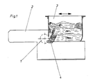
- the device shown only schematically in FIG. 1 comprises a rotor 1 designed as a solid shaft rotor, which is mounted in a fixed position in a machine stand 2 and to which the material to be shredded is fed via a horizontally displaceable hopper 3, the rear wall of which is the material to be shredded against the rotor 1 presses.
- the rotor 1 is associated with a fixedly arranged and comb-like shear bar 4, which is shown in FIGS. 2 and 3 on an enlarged scale.
- This shear bar 4 is arranged as close as possible to the rotor 1, so that only a narrow air gap a remains between the shear bar 4 and the outer surface of the rotor 1 (see FIG. 3).
- the bed knife 4 forms an angle ⁇ ⁇ 90 ° with the leading lateral surface of the rotor 1 (see FIG. 2).
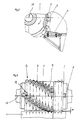
- the outer surface of the drivable rotor 1 is equipped with cutting bodies 5 which are each arranged in the form of a helix 12 according to FIG. 3.
- Each cutting body 5 is fastened in a groove 9 assigned only to it, which is V-shaped and as a secant is formed and has an opening angle ⁇ of 90 ° (see Figure 4).
- each cutting body 5 is designed as a square cutting plate, which is supported in the assembled position with its lower half on the two flanks of the groove 9 and, with its upper, triangular half, forms the section that is effective for comminution.
- FIG. 4 shows that the cutting bodies 5 lying next to one another in the axial direction are arranged with an overcut.
- grooves 9 lie in mutually parallel planes which are perpendicular to the rotor axis 10, and that the circumferential surface of the rotor 1 between these grooves 9 has a smooth surface as seen in the circumferential direction.
- the counter cutting edge 4 engages like a comb between the rotating cutting bodies 5 (see FIG. 3).
- each cutting body 5 lies against a cutting body carrier 6 and is screwed to the latter by means of a screw 7 shown as an Allen screw (see FIG. 5).
- the cutting body carrier 6 is welded to the rotor 1.
- FIGS. 4 and 5 in particular show that each cutting body 5 can be rotated by 90 ° about its central turning axis 11 after it has been removed or before it is installed, and can therefore be used four times.
- the rotor 1 is equipped at both of its axial ends lying outside the working area of the cutting body 5 with a broaching body 8, the flight circle of which is somewhat smaller than that of the cutting body 5, and the shape of which corresponds to that of the cutting body 5.
- These clearing bodies 8 clear the inner area next to the side walls of the funnel 3 and thereby prevent material jamming in this area.
Landscapes
- Engineering & Computer Science (AREA)
- Food Science & Technology (AREA)
- Environmental & Geological Engineering (AREA)
- Crushing And Pulverization Processes (AREA)
Claims (10)
- Dispositif pour le broyage de résidus ou de déchets de bois, d'écorces, de matières plastiques, de cartonnages ou matériaux similaires, comportant un rotor cylindrique (1) pouvant être entraîné et dont la paroi périphérique est équipée de corps de coupe (5) qui sont fixés chacun dans une rainure (9) affectée à un seul corps de coupe (5), ces rainures (9) étant situées respectivement dans des plans parallèles entre eux et perpendiculaires à l'axe de rotor (10), la paroi périphérique du rotor (1) étant de configuration lisse entre les rainures (9), en direction circonférentielle, et une contre-lame (4), montée en position fixe, s'avançant à la manière d'un peigne entre les corps de coupe (5) en rotation, caractérisé par les particularités suivantes:a) les corps de coupe (5) sont disposés sur la paroi périphérique du rotor (1), selon au moins une ligne en hélice (23);b) chaque rainure (9) présente une section transversale en forme de "V";c) la partie active de chaque corps de coupe (5), vue en direction circonférentielle, présente une configuration approximativement en forme de triangle;d) chaque corps de coupe (5) présente une configuration carrée, et peut être tourné par pas de 90°, autour d'un axe d'indexage (11) central;e) seul un interstice (a) de faible épaisseur reste libre entre la contre-lame (4) et la paroi périphérique du rotor (1).
- Dispositif selon la revendication 1, caractérisé en ce que la rainure (9) en forme de "V" présente un angle d'ouverture (α) de 90°, et en ce que chaque corps de coupe (5) s'appuie, à l'état monté, sur les deux flancs de la rainure.
- Dispositif selon la revendication 1 ou 2, caractérisé en ce que chaque corps de coupe (5) est appuyé, par sa face arrière, sur un support (6) de corps de coupe sur lequel il est vissé.
- Dispositif selon la revendication 3, caractérisé en ce que le support (6) de corps de coupe est soudé sur le rotor (1).
- Dispositif selon l'une des revendications précédentes, caractérisé en ce que les corps de coupe (5), vus axialement, sont disposés de manière à se chevaucher.
- Dispositif selon l'une des revendications précédentes, caractérisé en ce que le rotor (1) est équipé, à chacune de ses extrémités axiales situées en-dehors de la zone de travail des corps de coupe (5), d'au moins un corps de déblaiement (8) dont la trajectoire circulaire est légèrement plus petite que celle des corps de coupe (5).
- Dispositif selon la revendication 6, caractérisé en ce que les corps de déblaiement (8) présentent la même forme que les corps de coupe (5).
- Dispositif selon l'une des revendications précédentes, caractérisé en ce que chaque rainure (9) est réalisée sous la forme d'une sécante.
- Dispositif selon l'une des revendications précédentes, caractérisé en ce que la contre-lame (4) forme avec la paroi périphérique du rotor (1) qui avance vers elle, un angle (β) ≦ 90°.
- Dispositif selon l'une des revendications précédentes, caractérisé en ce que sur la paroi périphérique du rotor, sont prévues au moins deux lignes en hélice (12) de corps de coupe, qui sont décalées de 180° l'une par rapport à l'autre, qui s'étendent chacune sur seulement la moitié environ de la circonférence du rotor et sur la moitié environ de la longueur du rotor, et qui communiquent respectivement au matériau broyé des impulsions dans les sens axiaux opposés vers le milieu du rotor.
Priority Applications (1)
| Application Number | Priority Date | Filing Date | Title |
|---|---|---|---|
| AT90104879T ATE89193T1 (de) | 1989-03-15 | 1990-03-15 | Vorrichtung zum zerkleinern von rest- und abfallhoelzern. |
Applications Claiming Priority (4)
| Application Number | Priority Date | Filing Date | Title |
|---|---|---|---|
| DE3908395 | 1989-03-15 | ||
| DE19893908395 DE3908395C2 (de) | 1989-03-15 | 1989-03-15 | Vorrichtung zum Zerkleinern von Rest- und Abfallhölzern |
| DE3938820A DE3938820A1 (de) | 1989-03-15 | 1989-11-23 | Vorrichtung zum zerkleinern von rest- und abfallhoelzern |
| DE3938820 | 1989-11-23 |
Publications (3)
| Publication Number | Publication Date |
|---|---|
| EP0387868A2 EP0387868A2 (fr) | 1990-09-19 |
| EP0387868A3 EP0387868A3 (fr) | 1991-01-30 |
| EP0387868B1 true EP0387868B1 (fr) | 1993-05-12 |
Family
ID=25878821
Family Applications (1)
| Application Number | Title | Priority Date | Filing Date |
|---|---|---|---|
| EP90104879A Expired - Lifetime EP0387868B1 (fr) | 1989-03-15 | 1990-03-15 | Dispositif de broyage pour déchets de bois |
Country Status (2)
| Country | Link |
|---|---|
| EP (1) | EP0387868B1 (fr) |
| DE (2) | DE3938820A1 (fr) |
Families Citing this family (13)
| Publication number | Priority date | Publication date | Assignee | Title |
|---|---|---|---|---|
| DE4200796A1 (de) * | 1992-01-15 | 1993-05-27 | Dieter Knauss | Holzzerkleinerungsvorrichtung und messerelement fuer eine holzzerkleinerungsvorrichtung |
| AT399670B (de) * | 1992-11-04 | 1995-06-26 | Lindner Ges M B H Maschf | Vorrichtung zum zerkleinern von abfällen |
| DE4242740C2 (de) * | 1992-12-17 | 1998-09-10 | Holz Metall Abfall Recyclingte | Zerkleinerungsmaschine |
| EP0724550A4 (fr) * | 1993-10-20 | 1998-07-01 | Universal Greening Pty Ltd | Appareil de compostage |
| DE29504464U1 (de) * | 1995-03-16 | 1995-05-11 | Greß Holzaufbereitungs GmbH, 07356 Lobenstein | Anlage zur Verarbeitung von Holz, insbesondere Altholz |
| DE29515768U1 (de) * | 1995-10-04 | 1995-12-07 | Holz-, Metall-, Abfall-, Recyclingtechnik Gmbh, 79576 Weil Am Rhein | Schneidwerkzeug für Zerkleinerungsmaschinen |
| EP0908238A1 (fr) | 1997-10-06 | 1999-04-14 | UNTERWURZACHER PATENTVERWERTUNGSGESELLSCHAFT mbH | Dispositif déchiqueteur de matériaux |
| AT406354B (de) * | 1998-07-20 | 2000-04-25 | Wilhelm Bluemlinger | Zerkleinerungsvorrichtung |
| FR2785205B1 (fr) | 1998-10-30 | 2001-01-26 | Phenix Ind | Dispositif de broyage de dechets |
| FR2785202B1 (fr) * | 1999-05-19 | 2000-12-01 | Guy Auguste Emile Sosson | Machine a dechiqueter les objets emcombrants |
| IT1396480B1 (it) | 2009-10-23 | 2012-12-14 | C M G S P A | Perfezionamenti in macchine per triturare materiali vari come blocchi di plastica, residui di legno, cartonage e cosi' via. |
| CN103480469A (zh) * | 2013-09-02 | 2014-01-01 | 胡必胜 | 一种塑料碎片破碎辊轮 |
| CN111841817B (zh) * | 2020-07-23 | 2021-09-21 | 苏州贝基电子科技有限公司 | 一种紫砂原矿材料加工系统与加工方法 |
Citations (2)
| Publication number | Priority date | Publication date | Assignee | Title |
|---|---|---|---|---|
| DE2702177A1 (de) * | 1977-01-20 | 1978-07-27 | Kloeckner Gmbh & Co Geb | Walzenzerkleinerungsmaschine |
| DE2943567A1 (de) * | 1979-10-29 | 1981-04-30 | Peter 5439 Bretthausen Voelskow | Reisszahnwalze und damit bestueckte reisswalenzerkleinerungsmaschinen |
Family Cites Families (2)
| Publication number | Priority date | Publication date | Assignee | Title |
|---|---|---|---|---|
| US3216470A (en) * | 1962-07-09 | 1965-11-09 | Soderhamns Verkst Er Ab | Method and a machine for producing wood particles |
| US3202369A (en) * | 1963-01-16 | 1965-08-24 | Steel Briquette Corp | Rotary sheet metal tearing devices |
-
1989
- 1989-11-23 DE DE3938820A patent/DE3938820A1/de not_active Ceased
-
1990
- 1990-03-15 EP EP90104879A patent/EP0387868B1/fr not_active Expired - Lifetime
- 1990-03-15 DE DE9090104879T patent/DE59001396D1/de not_active Expired - Fee Related
Patent Citations (2)
| Publication number | Priority date | Publication date | Assignee | Title |
|---|---|---|---|---|
| DE2702177A1 (de) * | 1977-01-20 | 1978-07-27 | Kloeckner Gmbh & Co Geb | Walzenzerkleinerungsmaschine |
| DE2943567A1 (de) * | 1979-10-29 | 1981-04-30 | Peter 5439 Bretthausen Voelskow | Reisszahnwalze und damit bestueckte reisswalenzerkleinerungsmaschinen |
Also Published As
| Publication number | Publication date |
|---|---|
| DE3938820A1 (de) | 1991-05-29 |
| EP0387868A2 (fr) | 1990-09-19 |
| DE59001396D1 (de) | 1993-06-17 |
| EP0387868A3 (fr) | 1991-01-30 |
Similar Documents
| Publication | Publication Date | Title |
|---|---|---|
| DE69129014T2 (de) | Zerkleinerer | |
| EP1731223B1 (fr) | Désintégrateur des déchets | |
| EP2679309B1 (fr) | Dispositif de broyage comprenant un rotor de broyage avec lame traversante | |
| DE3782387T2 (de) | Muellzerkleinerungsmaschine und seitenschienen dafuer. | |
| EP0387868B1 (fr) | Dispositif de broyage pour déchets de bois | |
| EP0529221B1 (fr) | Dispositif de broyage | |
| EP2218507A2 (fr) | Dispositif de broyage de matériaux de chargement dotés d'éléments de démoulage | |
| DE102009060523A1 (de) | Zerkleinerungsvorrichtung mit Gegenmessereinrichtung | |
| DE3112639C2 (fr) | ||
| DE2256524A1 (de) | Verfahren und vorrichtung zum zerkleinern von gut in kleine stuecke | |
| DE2516111C2 (de) | Zerkleinerungsvorrichtung, insbesondere zur Verarbeitung von Papier und Kunststoffmaterial | |
| EP1497032B1 (fr) | Dispositif de broyage | |
| DE2256267C3 (de) | Mit Scherwirkung arbeitender Zerkleinerer | |
| DE2164566A1 (de) | Zerkleinerungsaggregat | |
| DE2502665A1 (de) | Abfallzerkleinerungsvorrichtung | |
| DE3874408T2 (de) | Zerkleinerungsapparat. | |
| DE3908395C2 (de) | Vorrichtung zum Zerkleinern von Rest- und Abfallhölzern | |
| DE102019108306A1 (de) | Schneidmühle zum schneidenden Zerkleinern von Proben | |
| AT395838B (de) | Messerwalze fuer eine vorrichtung zum vorzerkleinern von gefriergut | |
| EP2564930B1 (fr) | Hache | |
| DE10113953C1 (de) | Vorrichtung zum Zerkleinern von Kunststoffgebilden mit geringer Materialstärke | |
| DE3827767C2 (fr) | ||
| DE9418904U1 (de) | Spänezerkleinerer | |
| DE7818838U1 (de) | Maschine zum zerkleinern von abfallstoffen | |
| EP2549892B1 (fr) | Porte-couteaux pour dispositif de désintégration de matière organique |
Legal Events
| Date | Code | Title | Description |
|---|---|---|---|
| PUAI | Public reference made under article 153(3) epc to a published international application that has entered the european phase |
Free format text: ORIGINAL CODE: 0009012 |
|
| AK | Designated contracting states |
Kind code of ref document: A2 Designated state(s): AT CH DE FR IT LI |
|
| ITCL | It: translation for ep claims filed |
Representative=s name: MODIANO & ASSOCIATI S.R.L. |
|
| EL | Fr: translation of claims filed | ||
| PUAL | Search report despatched |
Free format text: ORIGINAL CODE: 0009013 |
|
| AK | Designated contracting states |
Kind code of ref document: A3 Designated state(s): AT CH DE FR IT LI |
|
| 17P | Request for examination filed |
Effective date: 19910220 |
|
| 17Q | First examination report despatched |
Effective date: 19920311 |
|
| GRAA | (expected) grant |
Free format text: ORIGINAL CODE: 0009210 |
|
| RAP1 | Party data changed (applicant data changed or rights of an application transferred) |
Owner name: KLOECKNER MASCHINEN- UND ANLAGENBAU GMBH |
|
| AK | Designated contracting states |
Kind code of ref document: B1 Designated state(s): AT CH DE FR IT LI |
|
| REF | Corresponds to: |
Ref document number: 89193 Country of ref document: AT Date of ref document: 19930515 Kind code of ref document: T |
|
| REF | Corresponds to: |
Ref document number: 59001396 Country of ref document: DE Date of ref document: 19930617 |
|
| ET | Fr: translation filed | ||
| ITF | It: translation for a ep patent filed | ||
| ITPR | It: changes in ownership of a european patent |
Owner name: CAMBIO RAGIONE SOCIALE;BMH WOOD TECHNOLOGY GMBH |
|
| REG | Reference to a national code |
Ref country code: CH Ref legal event code: PFA Free format text: BMH WOOD TECHNOLOGY GMBH |
|
| REG | Reference to a national code |
Ref country code: FR Ref legal event code: CD |
|
| PGFP | Annual fee paid to national office [announced via postgrant information from national office to epo] |
Ref country code: AT Payment date: 19960311 Year of fee payment: 7 |
|
| PGFP | Annual fee paid to national office [announced via postgrant information from national office to epo] |
Ref country code: FR Payment date: 19960313 Year of fee payment: 7 |
|
| PGFP | Annual fee paid to national office [announced via postgrant information from national office to epo] |
Ref country code: CH Payment date: 19960328 Year of fee payment: 7 |
|
| PG25 | Lapsed in a contracting state [announced via postgrant information from national office to epo] |
Ref country code: AT Effective date: 19970315 |
|
| PG25 | Lapsed in a contracting state [announced via postgrant information from national office to epo] |
Ref country code: LI Effective date: 19970331 Ref country code: CH Effective date: 19970331 |
|
| REG | Reference to a national code |
Ref country code: CH Ref legal event code: PL |
|
| PG25 | Lapsed in a contracting state [announced via postgrant information from national office to epo] |
Ref country code: FR Free format text: LAPSE BECAUSE OF NON-PAYMENT OF DUE FEES Effective date: 19971128 |
|
| REG | Reference to a national code |
Ref country code: FR Ref legal event code: ST |
|
| PGFP | Annual fee paid to national office [announced via postgrant information from national office to epo] |
Ref country code: DE Payment date: 20010303 Year of fee payment: 12 |
|
| PG25 | Lapsed in a contracting state [announced via postgrant information from national office to epo] |
Ref country code: DE Free format text: LAPSE BECAUSE OF NON-PAYMENT OF DUE FEES Effective date: 20021001 |
|
| PG25 | Lapsed in a contracting state [announced via postgrant information from national office to epo] |
Ref country code: IT Free format text: LAPSE BECAUSE OF NON-PAYMENT OF DUE FEES;WARNING: LAPSES OF ITALIAN PATENTS WITH EFFECTIVE DATE BEFORE 2007 MAY HAVE OCCURRED AT ANY TIME BEFORE 2007. THE CORRECT EFFECTIVE DATE MAY BE DIFFERENT FROM THE ONE RECORDED. Effective date: 20050315 |
|
| PLBE | No opposition filed within time limit |
Free format text: ORIGINAL CODE: 0009261 |
|
| STAA | Information on the status of an ep patent application or granted ep patent |
Free format text: STATUS: NO OPPOSITION FILED WITHIN TIME LIMIT |