EP0239104A2 - Cutting mechanism for a document shredder - Google Patents
Cutting mechanism for a document shredder Download PDFInfo
- Publication number
- EP0239104A2 EP0239104A2 EP87104455A EP87104455A EP0239104A2 EP 0239104 A2 EP0239104 A2 EP 0239104A2 EP 87104455 A EP87104455 A EP 87104455A EP 87104455 A EP87104455 A EP 87104455A EP 0239104 A2 EP0239104 A2 EP 0239104A2
- Authority
- EP
- European Patent Office
- Prior art keywords
- cutting
- scraper
- cutting device
- strips
- plates
- Prior art date
- Legal status (The legal status is an assumption and is not a legal conclusion. Google has not performed a legal analysis and makes no representation as to the accuracy of the status listed.)
- Granted
Links
Images

Classifications
-
- B—PERFORMING OPERATIONS; TRANSPORTING
- B02—CRUSHING, PULVERISING, OR DISINTEGRATING; PREPARATORY TREATMENT OF GRAIN FOR MILLING
- B02C—CRUSHING, PULVERISING, OR DISINTEGRATING IN GENERAL; MILLING GRAIN
- B02C18/00—Disintegrating by knives or other cutting or tearing members which chop material into fragments
- B02C18/0007—Disintegrating by knives or other cutting or tearing members which chop material into fragments specially adapted for disintegrating documents
-
- B—PERFORMING OPERATIONS; TRANSPORTING
- B02—CRUSHING, PULVERISING, OR DISINTEGRATING; PREPARATORY TREATMENT OF GRAIN FOR MILLING
- B02C—CRUSHING, PULVERISING, OR DISINTEGRATING IN GENERAL; MILLING GRAIN
- B02C18/00—Disintegrating by knives or other cutting or tearing members which chop material into fragments
- B02C18/06—Disintegrating by knives or other cutting or tearing members which chop material into fragments with rotating knives
- B02C18/14—Disintegrating by knives or other cutting or tearing members which chop material into fragments with rotating knives within horizontal containers
- B02C18/142—Disintegrating by knives or other cutting or tearing members which chop material into fragments with rotating knives within horizontal containers with two or more inter-engaging rotatable cutter assemblies
-
- B—PERFORMING OPERATIONS; TRANSPORTING
- B02—CRUSHING, PULVERISING, OR DISINTEGRATING; PREPARATORY TREATMENT OF GRAIN FOR MILLING
- B02C—CRUSHING, PULVERISING, OR DISINTEGRATING IN GENERAL; MILLING GRAIN
- B02C18/00—Disintegrating by knives or other cutting or tearing members which chop material into fragments
- B02C18/06—Disintegrating by knives or other cutting or tearing members which chop material into fragments with rotating knives
- B02C18/16—Details
- B02C18/18—Knives; Mountings thereof
- B02C18/182—Disc-shaped knives
-
- B—PERFORMING OPERATIONS; TRANSPORTING
- B02—CRUSHING, PULVERISING, OR DISINTEGRATING; PREPARATORY TREATMENT OF GRAIN FOR MILLING
- B02C—CRUSHING, PULVERISING, OR DISINTEGRATING IN GENERAL; MILLING GRAIN
- B02C18/00—Disintegrating by knives or other cutting or tearing members which chop material into fragments
- B02C18/0007—Disintegrating by knives or other cutting or tearing members which chop material into fragments specially adapted for disintegrating documents
- B02C2018/0069—Disintegrating by knives or other cutting or tearing members which chop material into fragments specially adapted for disintegrating documents with stripping devices
Definitions
- the invention relates to a cutting device for document shredders according to the preamble of the main claim, especially to so-called particle cutters with a longitudinal cut and additional cross separation of the material.
- DE-PS 27 49 482 already discloses a scraper system for the shaft bottom and cutting roller surface which is specifically intended for document shredders of the type in question, which consists of strippers which are arranged next to one another and fully encompass the roller base and additionally comprise auxiliary strippers which lie on the roller surface in a sector-like manner common bearing rods are lined up and held in this way in the housing, but this is precisely a construction that offers the fine and thus unstable cutting particles a wealth of possibilities to penetrate the spaces between the wipers and auxiliary wipers and the entire cutting unit is closed after a very short time clog.
- the cutting unit shown first shows scraper plates 7 for the cutting rollers 1, 2, in which strippers 7, which are mounted over the entire roller width B between two disk-like cutting blades 3, 4 via rods 5 and 6 in the side plates P, are sector-like and with an adapted radius R extend to the roller core la, 2a and additional Wiper elements rest on the surface or the outer circumference 3a, 4a of the cutting disks or circular knives 3, 4.
- the novelty is that the holding rods 5, 6 for the wipers 7 are designed in the form of strips and that, on the one hand, the areas 5a and 6a adjacent to the cutting rollers 1, 2 rest positively on the outer circumference 3a, 4a of the circular knives 3, 4 and on the other hand have a hook-shaped taper 5b or 6b, which engage in an undercut groove 7b on the back of each scraper plate 7, the holding rods 5 and 6 for the scraper plates 7 being mirror images of one another in cross section and at a distance x from one another, diverging from respective rod base 5a or 6a forth individual strips 1, 2 are formed and the connection between rod base 5a or 6a and groove 7b of the stripper plates 7 is dovetail-shaped.
- a very special advantage of the dovetail design is, however, that the sensitive tip parts (lugs 7a) of the stripper plates 7 are held directly by the dovetail base 7b of the stripper strips according to the dash-dotted line K and are thus strengthened or supported in terms of strength. Also important is the smooth outer contour of the strips 5 and 6, on which no particles can therefore adhere.
- the stripping lugs 7a on the side of the cutting gap Sp are at different distances a, b, c, d from the center M of the overlap of the cutting disks 3 and 4, the sum of the Total distances a + b and c + d from nose 7a to nose 7a are different in size for each of the two cutting rollers 1 and 2, respectively.
- the main result of this is that the fibrous clumps of cuttings W inevitably adhering to the scraper noses 7a on the cut material exit side A do not reach the center M of the cutting disc overlap area at the same time as the roll is returning and there, in addition to the material already present in the cutting gap, are pressed and solidified on the roll base becomes.
- this arrangement guarantees that such material never reaches the scraper noses 7a on the paper feed side E at the same time, but always one after the other, thus virtually halving the sum of the scraper resistances for the drive, or greatly reducing the impact load.
- the cutting rollers 1, 2 are coupled to the drive wheel 10 via gear wheels 8, 9.
- the wiper strips are clamped by screws 11 in the bearing or housing side plates P, in which the roller bearings 12 are also located.
- types I to IV of the wiper strips are also to be used to solve the same problem, as indicated by FIGS. 3 to 6 bar, in which the individual stripper plates 20, 20 ⁇ or 20 ⁇ have a socket-like extension 24 or 25 or 26 which protrudes from the outer circumference 13a or 14a of the circular knives 13 and 14 and projects into the space between the stripper strips 15 to 18 and is penetrated by at least one continuous fastening rod 19.
- the special design in detail provides that the areas of the scraper strips 15 to 18 which are in each case form-fitting on the outer circumference 13a and 14a of the circular knives 13 and 14 engage in corresponding grooves 21 and 22 of the scraper plates 20 and 20 'or corresponding recesses 23 in these 20 ⁇ penetrate, wherein in variants II and III the paired wiper strips 17 and 18 are connected to each other by back parts 17a and 18a and thus embrace the bases 24 and 25 of the wiper plates 20 and 20 ⁇ like a hood.
- the wiper strips are each connected by screws 11 to the side plates P of the device housing.
Abstract
Description
Die Erfindung bezieht sich auf ein Schneidwerk für Aktenvernichter nach dem Oberbegriff des Hauptanspruchs, speziell dabei auf sogenannte Partikelschneider mit Längsschnitt und zusätzlicher Quertrennung des Materials. Zwar ist bereits aus der DE-PS 27 49 482 ein für Aktenvernichter der hier zur Rede stehenden Art speziell gedachtes Abstreifersystem für Wellengrund und Schneidwalzenoberfläche bekannt, das aus nebeneinandergereihten und den Walzengrund voll umfassenden Abstreifern und zusätzlich auf der Walzenoberfläche sektorartig aufliegenden Hilfsabstreifern besteht, die auf gemeinsamen Lagerstangen aufgereiht und auf diese Weise im Gehäuse gehalten sind, jedoch ist gerade dies eine Konstruktion, die den feinen und somit instabilen Schneidpartikelchen eine Fülle von Möglichkeiten bietet, in die Räume zwischen den Abstreifern und Hilfsabstreifern einzudringen und das gesamte Schneidwerk nach bereits kürzester Zeit zu verstopfen.The invention relates to a cutting device for document shredders according to the preamble of the main claim, especially to so-called particle cutters with a longitudinal cut and additional cross separation of the material. DE-PS 27 49 482 already discloses a scraper system for the shaft bottom and cutting roller surface which is specifically intended for document shredders of the type in question, which consists of strippers which are arranged next to one another and fully encompass the roller base and additionally comprise auxiliary strippers which lie on the roller surface in a sector-like manner common bearing rods are lined up and held in this way in the housing, but this is precisely a construction that offers the fine and thus unstable cutting particles a wealth of possibilities to penetrate the spaces between the wipers and auxiliary wipers and the entire cutting unit is closed after a very short time clog.
Aufgabe der vorliegenden Erfindung ist es daher, die aus dem Stand der Technik bekannte Grundausbildung eines Abstreifersystems derart zu modifizieren, daß sich auch bei den Partikelschneidern ein optimales Arbeitsergebnis ergibt.It is therefore the object of the present invention to modify the basic design of a scraper system known from the prior art in such a way that an optimum work result also results with the particle cutters.
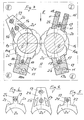
Die Lösung dieser Aufgabe ist den Patentansprüchen sowie den Zeichnungen zu entnehmen. Letztere zeigen weitestgehend schematisch dargestellt in Fig. 1 ein Aktenschneidwerk im Querschnitt, in Fig. 2 ein Schneidwerk verkleinert in Ansicht, in Fig. 3 verschiedene Alternativen zu Fig. 1 und in Fig. 4 bis 6 die Abstreiferbleche aus Fig. 3 als Einzelheit.The solution to this problem can be found in the patent claims and the drawings. The latter show largely schematically shown in Fig. 1 a file cutter in cross section, in Fig. 2 a cutter reduced in view, in Fig. 3 different alternatives to Fig. 1 and in Figs. 4 to 6 the scraper plates from Fig. 3 as a detail.
Generell zeigt das dargestellte Schneidwerk zunächst einmal Abstreiferbleche 7 für die Schneidwalzen 1, 2, bei dem sich über die gesamte Walzenbreite B zwischen jeweils zwei scheibenartigen Schneidmessern 3, 4 über Stangen 5 bzw. 6 in den Seitenplatten P gelagerte Abstreifer 7 sektorartig und mit angepaßtem Radius R bis auf den Walzenkern la, 2a hin erstrecken und zusätzliche Abstreiferelemente auf der Oberfläche bzw. dem Außenumfang 3a, 4a der Schneidscheiben bzw. Kreismesser 3, 4 aufliegen.Generally, the cutting unit shown first shows
Gemäß der vorliegenden Erfindung besteht das Neue nun darin, daß die Haltestangen 5, 6 für die Abstreifer 7 leistenförmig ausgebildet sind und die den Schneidwalzen 1, 2 benachbarten Bereiche 5a bzw. 6a einerseits formschlüssig auf dem Außenumfang 3a, 4a der Kreismesser 3, 4 aufliegen und andererseits eine im Querschnitt hakenförmige Ausspitzung 5b bzw. 6b aufweisen, die in eine hinterschnittene Nut 7b am Rücken jedes Abstreiferbleches 7 eingreifen, wobei die Haltestangen 5 bzw. 6 für die Abstreiferbleche 7 als im Querschnitt spiegelbildlich und mit Abstand x zueinander liegende, divergierend vom jeweiligen Stangenfuß 5a bzw. 6a her nach außen verlaufende Einzelleisten 1, 2 ausgebildet sind und die Verbindung zwischen Stangenfuß 5a bzw. 6a und Nut 7b der Abstreiferbleche 7 schwalbenschwanzförmig ausgebildet ist.According to the present invention, the novelty is that the
Die Vorteile dieser Ausführung liegen nun zum einen darin, daß keinerlei Teile oder taschenartige Hohlräume zwischen Haltestangen mehr vorhanden sind, in denen sich Schneidpartikelchen festsetzen können, und zwar sowohl bei Walzenvor- oder Rücklauf; was tatsächlich noch an den Nasen 7a der Abstreiferbleche 7 an Schneidpartikelchen innerhalb der Nuten am Scheibenaußenumfang vorbeigehen könnte, fällt spätestens im Spalt zwischen den divergierenden Haltestangen 5 und 6 aus.The advantages of this design are, on the one hand, that there are no parts or pocket-like cavities between the holding rods, in which cutting particles can become lodged, both when the roll is moving forward or backward; What actually could still go past the lugs 7a of the
Ein ganz besonderer Vorteil der Schwalbenschwanzausbildung liegt jedoch vor allem darin, daß die empfindlichen Spitzenteile (Nasen 7a) der Abstreiferbleche 7 durch den Schwalbenschwanzfuß 7b der Abstreiferleisten gemäß der strichpunktierten Linie K unmittelbar gehalten und somit in festigkeitsmäßigem Sinne verstärkt bzw. abgestützt werden. Wichtig ist zudem die glatte Außenkontur der Leisten 5 bzw. 6, an denen sich somit auch keine Partikel festsetzen können.A very special advantage of the dovetail design is, however, that the sensitive tip parts (lugs 7a) of the
Ein weiteres wesentliches Merkmal der Erfindung besteht noch darin, daß die auf der Seite des Schneidspalts Sp liegenden Abstreifernasen 7a unterschiedlich weit a, b, c, d von der Mitte M der Uberdeckung der Schneidscheiben 3 und 4 entfernt liegen, wobei zudem noch die Summe der Gesamtabstände a + b bzw. c + d von Nase 7a zu Nase 7a bei jeder der beiden Schneidwalzen 1 bzw. 2 unterschiedlich groß ist. Hierdurch wird vor allem erreicht, daß das zwangsläufig an den Abstreifernasen 7a auf der Schnittgutaustrittsseite A anhaftende faserige Schnittgutgewölle W, beim Walzenrücklauf nicht zum gleichen Zeitpunkt in die Mitte M des Schneidscheibenüberdeckungsbereiches gelangt und dort zusätzlich zum ohnehin im Schneidspalt vorhandene Material auf den Walzengrund gepreßt und verfestigt wird. Zudem garantiert diese Anordnung, daß solches Material auch auf der Papiereinzugsseite E niemals zum gleichen Zeitpunkt, sondern stets nacheinander an die dortigen Abstreifernasen 7a gelangt und für den Antrieb somit die Summe der Abstreiferwiderstände quasi halbiert, bzw. die Stoßbelastung stark verringert wird.Another essential feature of the invention is that the stripping lugs 7a on the side of the cutting gap Sp are at different distances a, b, c, d from the center M of the overlap of the
Letztlich ist es noch erfindungserheblich, daß die Schultern 7c der Abstreiferbleche 7 außerhalb des Umfangs der Kreismesser 3, 4 liegen und der innere Verlauf der Schwalbenschwanznut 7b dekkungsgleich mit demjenigen der Kreismesseraußenkontur 3a, 4a ist.Ultimately, it is still relevant to the invention that the shoulders 7c of the
Antriebsmäßig sind im übrigen wie Fig. 2 noch zeigt, die Schneidwalzen 1, 2 über Zahnräder 8, 9 mit dem Antriebsrad 10 gekoppelt.2, the
Die Abstreiferleisten sind über Schrauben 11 in den Lager- bzw. Gehäuseseitenplatten P verspannt, in denen sich auch die Walzenlagerungen 12 befinden.The wiper strips are clamped by
Alternativ zu der zuvor beschriebenen Ausführung nach Fig. 1 sind zur Lösung der gleichen Aufgabenstellung aber auch, wie die Fig. 3 bis 6 andeuten, Bauarten I bis IV der Abstreiferleisten denk bar, bei denen die einzelnen Abstreiferbleche 20, 20ʹ oder 20ʺ einen aus dem Außenumfang 13a bzw. 14a der Kreismesser 13 und 14 herausragenden, sockelartigen Ansatz 24 bzw. 25 bzw. 26 aufweisen, der in den Zwischenraum zwischen den Abstreiferleisten 15 bis 18 ragt und von mindestens einer durchlaufenden Befestigunsstange 19 durchsetzt ist.As an alternative to the previously described embodiment according to FIG. 1, types I to IV of the wiper strips are also to be used to solve the same problem, as indicated by FIGS. 3 to 6 bar, in which the
Die spezielle Ausgestaltung im Detail sieht dabei vor, daß die jeweils formschlüssig am Außenumfang 13a und 14a der Kreismesser 13 und 14 anliegenden Bereiche der Abstreiferleisten 15 bis 18 in entsprechende Nuten 21 bzw. 22 der Abstreiferbleche 20 bzw. 20ʹ eingreifen oder entsprechende Aussparungen 23 in diesen 20ʺ durchdringen, wobei bei den Varianten II und III die paarweisen Abstreiferleisten 17 und 18 durch Rückenpartien 17a bzw. 18a miteinander verbunden sind und die Sockel 24 bzw. 25 der Abstreiferbleche 20 bzw. 20ʹ somit haubenartig umgreifen. Auch bei diesen Lösungen sind die Abstreiferleisten jeweils durch Schrauben 11 mit den Seitenplatten P des Gerätegehäuses verbunden.The special design in detail provides that the areas of the
- 1 Schneidwalze1 cutting roller
- 2 Schneidwalze2 cutting roller
- 1ʹ Walzenkern1ʹ roll core
- 2ʹ Walzenkern2ʹ roller core
- 3 Kreismesser3 circular knives
- 4 Kreismesser4 circular knives
- 3a Außenumfang3a outer circumference
- 4a Außenumfang4a outer circumference
- 5 Abstreiferleisten5 wiper strips
- 6 Abstreiferleisten6 wiper strips
- 5a Bereich an den Walzen5a area on the rollers
- 6a Bereich an den Walzen6a area on the rollers
- 5b Ausspitzung5b thinning
- 6b Ausspitzung6b thinning
- 7 Abstreiferblech7 scraper plate
- 7a Nase7a nose
- 7b Nut7b groove
- 7c Schulter7c shoulder
- 8 Zahnrad8 gear
- 9 Zahnrad9 gear
- 10 Antriebsritzel10 drive sprockets
- 11 Verschraubung11 screw connection
- 12 Walzenlagerung12 roller bearings
- 13 Kreismesser13 circular knives
- 13a Außenumfang13a outer circumference
- 14 Kreismesser14 circular knives
- 14a Außenumfang14a outer circumference
- 15 Abstreiferleiste I15 wiper strip I
- 16 Abstreiferleiste IV16 wiper strip IV
- 17 Abstreiferleiste II17 Wiper strip II
- 17a Rückenpartie17a back section
- 18 Abstreiferleiste III18 Wiper strip III
- 18a Rückenpartie18a back section
- 19 durchlaufende Haltestangen19 continuous handrails
- 20 Abstreiferblech20 wiper plate
- 20ʹ Abstreiferblech20ʹ scraper plate
- 20ʺ Abstreiferblech20ʺ scraper plate
- 21 Nut21 groove
- 22 Nut22 groove
- 23 Aussparung23 recess
- 24 Sockel24 bases
- 25 Sockel25 bases
- 26 Sockel26 base
- a Nasenabstanda Nose spacing
- b Nasenabstandb Nose spacing
- c Nasenabstandc Nose spacing
- d Nasenabstandd nose distance
- x Leistenabstandx bar spacing
- A SchnittgutaustrittsseiteA clippings exit side
- E PapiereinzugseiteE Paper feed side
- K StützlinieK support line
- M SchneidwerkmitteM center of the cutting unit
- P SeitenplattenP side plates
- R KreismesserradiusR circular knife radius
- Sp SchneidspaltSp cutting gap
- W GewölleW vault
Claims (8)
dadurch gekennzeichnet,
daß die Haltestangen (5, 6) für die Abstreifer (7) leistenförmig ausgebildet sind und die den Schneidwalzen (1, 2) benachbarten Bereiche (5a bzw. 6a) der Leisten (5, 6) einerseits formschlüssig auf dem Außenumfang (3a, 4a) der Kreismesser (3, 4) aufliegen und andererseits eine im Querschnitt hakenförmige Ausspitzung (5b bzw. 6b) aufweisen, die in eine hinterschnittene Nut (7b) am Rücken jedes Abstreiferbleches (7) eingreifen.1. Cutting device for document shredder consisting of a pair of cutting rollers (1, 2) guided in lateral bearing plates (P) with disk-shaped circular knives (3, 4) that partially overlap in the area of the cutting gap (Sp) and between them except for the roller core (1ʹ, 2ʹ) protruding scraper plates (7) lined up on rods (5, 6) lying parallel to the cutting rollers (1, 2) with pointed lugs (7a) approaching the roller core (1ʹ, 2ʹ),
characterized,
that the support rods (5, 6) for the wipers (7) are strip-shaped and the areas (5a and 6a) of the strips (5, 6) adjacent to the cutting rollers (1, 2) have a positive fit on the outer circumference (3a, 4a ) of the circular knife (3, 4) and on the other hand have a hook-shaped cutout (5b or 6b) which engages in an undercut groove (7b) on the back of each stripper plate (7).
dadurch gekennzeichnet,
daß die Haltestangen (5 bzw. 6) für die Abstreiferbleche (7) als im Querschnitt spiegelbildlich und mit Abstand (x) zueinander liegende, divergierend vom jeweiligen Stangenfuß (5a bzw. 6a) her nach außen verlaufende Einzelleisten (1, 2) ausgebildet sind und die Verbindung zwischen Stangenfuß (5a bzw. 6a) und Nut (7b) der Abstreiferbleche (7) schwalbenschwanzförmig ausgebildet ist.2. Cutting device according to claim 1,
characterized,
that the support rods (5 or 6) for the stripper plates (7) are designed as mirror strips in cross section and at a distance (x) from one another, diverging from the respective rod base (5a or 6a) and extending outwardly to individual strips (1, 2) and the connection between the rod foot (5a or 6a) and the groove (7b) of the stripper plates (7) is dovetail-shaped.
dadurch gekennzeichnet,
daß die auf der Seite des Schneidspalts (Sp) liegenden Abstreifernasen (7a) unterschiedlich weit (a, b, c, d)von der Mitte (M) der Überdeckung der Schneidscheiben (3 und 4) entfernt liegen.3. Cutting device according to claims 1 and 2,
characterized,
that the stripping lugs (7a) on the side of the cutting gap (Sp) are at different distances (a, b, c, d) from the center (M) of the overlap of the cutting disks (3 and 4).
dadurch gekennzeichnet,
daß die Summe der Gesamtabstände (a+b bzw. c+d) von Nase (7a) zu Nase (a) bei jeder der beiden Schneidwalzen (1 bzw. 2) unterschiedlich groß ist.4. Cutting device according to claims 1 to 3,
characterized,
that the sum of the total distances (a + b or c + d) from nose (7a) to nose (a) is different in size for each of the two cutting rollers (1 or 2).
dadurch gekennzeichnet,
daß die Schultern (7c) der Abstreiferbleche (7) außerhalb des Umfangs der Kreismesser (3, 4) liegen und der innere Verlauf der Schwalbenschwanznut (7b) deckungsgleich mit demjenigen der Kreismesseraußenkontur (3a, 4a) ist.5. Cutting device according to claims 1 to 4,
characterized,
that the shoulders (7c) of the scraper plates (7) lie outside the circumference of the circular knife (3, 4) and the inner course of the dovetail groove (7b) is congruent with that of the circular knife outer contour (3a, 4a).
dadurch gekennzeichnet,
daß die Abstreiferbleche (20, 20ʹ, 20ʺ) einen aus dem Außenumfang (13a bzw. 14a) der Kreismesser (13 und 14) herausragenden, sockelartigen Ansatz (24 bzw. 25 bzw. 26) aufweisen, der in den Zwischenraum zwischen den Abstreiferleisten (15 bis 18) ragt und von mindestens einer durchlaufenden Befestigungsstange (19) durchsetzt ist.6. Cutting device according to the preamble and partly according to the characterizing part of claim 1 and the preceding claims,
characterized,
that the scraper plates (20, 20ʹ, 20ʺ) have a base-like extension (24 or 25 or 26) which protrudes from the outer circumference (13a or 14a) of the circular knives (13 and 14) and which extends into the space between the scraper strips ( 15 to 18) protrudes and is penetrated by at least one continuous fastening rod (19).
dadurch gekennzeichnet,
daß die jeweils formschlüssig am Außenumfang (13a und 14a) der Kreismesser (13 und 14) anliegenden Bereiche der Abstreiferleisten (15 bis 18) in entsprechende Nuten (21 bzw. 22) der Abstreiferbleche (20 bzw. 20ʹ) eingreifen oder entsprechende Aussparungen (23) in diesen (20ʺ) durchdringen.7. Cutting device according to claim 6,
characterized,
that the areas of the scraper strips (15 to 18) which are in each case form-fitting on the outer circumference (13a and 14a) of the circular knives (13 and 14) engage in corresponding grooves (21 or 22) of the scraper plates (20 or 20ʹ) or corresponding recesses (23 ) penetrate into this (20ʺ).
dadurch gekennzeichnet,
daß die paarweisen Abstreiferleisten (17 und 18) durch Rückenpartien (17a bzw. 18a) miteinander verbunden sind und die Sockel (24 bzw. 25) der Abstreiferbleche (20 bzw. 20ʹ) somit haubenartig umgreifen.8. Cutting device according to claims 6 and 7,
characterized,
that the paired scraper strips (17 and 18) are connected to each other by back sections (17a and 18a) and thus encompass the bases (24 and 25) of the scraper plates (20 and 20ʹ) like a hood.
Applications Claiming Priority (4)
| Application Number | Priority Date | Filing Date | Title |
|---|---|---|---|
| DE3610539 | 1986-03-27 | ||
| DE3610537 | 1986-03-27 | ||
| DE19863610539 DE3610539C2 (en) | 1986-03-27 | 1986-03-27 | Scraper unit for the pair of cutting rollers of a document shredder |
| DE3610537A DE3610537C2 (en) | 1986-03-27 | 1986-03-27 | Scraper for the cutting rollers of document shredders |
Publications (3)
| Publication Number | Publication Date |
|---|---|
| EP0239104A2 true EP0239104A2 (en) | 1987-09-30 |
| EP0239104A3 EP0239104A3 (en) | 1988-08-03 |
| EP0239104B1 EP0239104B1 (en) | 1991-06-05 |
Family
ID=25842427
Family Applications (1)
| Application Number | Title | Priority Date | Filing Date |
|---|---|---|---|
| EP87104455A Expired - Lifetime EP0239104B1 (en) | 1986-03-27 | 1987-03-26 | Cutting mechanism for a document shredder |
Country Status (2)
| Country | Link |
|---|---|
| EP (1) | EP0239104B1 (en) |
| DE (1) | DE3770503D1 (en) |
Cited By (6)
| Publication number | Priority date | Publication date | Assignee | Title |
|---|---|---|---|---|
| FR2674147A1 (en) * | 1991-03-22 | 1992-09-25 | Schleicher & Co Int | DESTROYER OF DOCUMENTS. |
| EP0525491A1 (en) * | 1991-07-13 | 1993-02-03 | Hermann Schwelling | Stripper element for a small document shredder |
| WO1993025312A1 (en) * | 1992-06-12 | 1993-12-23 | Erema Engineering Recycling Maschinen Und Anlagen Gesellschaft M.B.H. | Device for plasticising thermoplastic material |
| EP0616850A2 (en) * | 1993-03-22 | 1994-09-28 | Hermann Schwelling | Document shredder |
| WO2016070948A1 (en) | 2014-11-07 | 2016-05-12 | Akten-Ex Gmbh & Co Kg | Destruction of printed paper |
| CN110064477A (en) * | 2019-04-29 | 2019-07-30 | 杭州铭展网络科技有限公司 | A kind of shredder convenient for safeguarding |
Citations (4)
| Publication number | Priority date | Publication date | Assignee | Title |
|---|---|---|---|---|
| FR2502979A1 (en) * | 1981-03-31 | 1982-10-08 | Schleicher Co Feinwerktech | RIPPER FINGER IN THE DEVICE OF A WASTE MACHINE FOR TEXT AND DATA MEDIA |
| GB2096017A (en) * | 1981-03-31 | 1982-10-13 | Schwelling Hermann | Cutting mechanism for paper shredders |
| DE2749482C2 (en) * | 1977-11-04 | 1986-01-09 | Feinwerktechnik Schleicher & Co, 7778 Markdorf | Cutting roller of a ripper |
| EP0174148A2 (en) * | 1984-08-31 | 1986-03-12 | Mochizuki Precision Machine Industries Co. Ltd. | Cutting apparatus |
-
1987
- 1987-03-26 EP EP87104455A patent/EP0239104B1/en not_active Expired - Lifetime
- 1987-03-26 DE DE8787104455T patent/DE3770503D1/en not_active Expired - Lifetime
Patent Citations (4)
| Publication number | Priority date | Publication date | Assignee | Title |
|---|---|---|---|---|
| DE2749482C2 (en) * | 1977-11-04 | 1986-01-09 | Feinwerktechnik Schleicher & Co, 7778 Markdorf | Cutting roller of a ripper |
| FR2502979A1 (en) * | 1981-03-31 | 1982-10-08 | Schleicher Co Feinwerktech | RIPPER FINGER IN THE DEVICE OF A WASTE MACHINE FOR TEXT AND DATA MEDIA |
| GB2096017A (en) * | 1981-03-31 | 1982-10-13 | Schwelling Hermann | Cutting mechanism for paper shredders |
| EP0174148A2 (en) * | 1984-08-31 | 1986-03-12 | Mochizuki Precision Machine Industries Co. Ltd. | Cutting apparatus |
Cited By (11)
| Publication number | Priority date | Publication date | Assignee | Title |
|---|---|---|---|---|
| FR2674147A1 (en) * | 1991-03-22 | 1992-09-25 | Schleicher & Co Int | DESTROYER OF DOCUMENTS. |
| EP0525491A1 (en) * | 1991-07-13 | 1993-02-03 | Hermann Schwelling | Stripper element for a small document shredder |
| WO1993025312A1 (en) * | 1992-06-12 | 1993-12-23 | Erema Engineering Recycling Maschinen Und Anlagen Gesellschaft M.B.H. | Device for plasticising thermoplastic material |
| AU668184B2 (en) * | 1992-06-12 | 1996-04-26 | Helmut Bacher | Device for plasticising thermoplastic material |
| EP0616850A2 (en) * | 1993-03-22 | 1994-09-28 | Hermann Schwelling | Document shredder |
| EP0616850A3 (en) * | 1993-03-22 | 1995-01-25 | Hermann Schwelling | Document shredder. |
| WO2016070948A1 (en) | 2014-11-07 | 2016-05-12 | Akten-Ex Gmbh & Co Kg | Destruction of printed paper |
| DE202015009627U1 (en) | 2014-11-07 | 2018-11-15 | Akten-Ex Gmbh & Co. Kg | Paper from a shredder |
| DE202015009629U1 (en) | 2014-11-07 | 2018-11-15 | Akten-Ex Gmbh & Co. Kg | Plant for shredding files |
| DE202015009626U1 (en) | 2014-11-07 | 2018-11-15 | Akten-Ex Gmbh & Co. Kg | paper shredder |
| CN110064477A (en) * | 2019-04-29 | 2019-07-30 | 杭州铭展网络科技有限公司 | A kind of shredder convenient for safeguarding |
Also Published As
| Publication number | Publication date |
|---|---|
| DE3770503D1 (en) | 1991-07-11 |
| EP0239104A3 (en) | 1988-08-03 |
| EP0239104B1 (en) | 1991-06-05 |
Similar Documents
| Publication | Publication Date | Title |
|---|---|---|
| DE2840337B2 (en) | Cutting set for meat grinders or the like. | |
| EP0497170B1 (en) | Document shredder with conveyor for the material to be shredded | |
| WO1994017981A1 (en) | Filter device for fluids, especially thermoplastic fluids | |
| EP0422272B1 (en) | Mixing and kneading device | |
| EP0239104B1 (en) | Cutting mechanism for a document shredder | |
| EP0287847B1 (en) | Cutting tool | |
| DE2338654C2 (en) | Shredding device, in particular document shredders | |
| DE3610537A1 (en) | SCRAPER FOR THE CUTTER ROLLERS OF PAPER CRUSHERS | |
| DE3539098A1 (en) | WASTE CRUSHING DEVICE AND SCHLEBERGLBER FOR THIS | |
| EP0291774A2 (en) | Shredder with rotating knives | |
| DE4242740A1 (en) | Disintegrator with securely mounted cutters for difficult materials | |
| EP0861696A1 (en) | Disk for screen or separator | |
| DE3509004A1 (en) | Belt-grinding machine | |
| DE4301787C1 (en) | Cutter for meat mincers | |
| DE1910385C3 (en) | Cutting device for cutting tea leaves | |
| DE3925098A1 (en) | Grinder - has wear parts on two rotating sections which are replaceable to extend component life | |
| DE3112838C2 (en) | Cutting unit for document shredders | |
| EP0635306A2 (en) | Stripping device for a document shredder | |
| DE2618254A1 (en) | Wood and paper refuse cutting drum - has discs mounted along shaft, each with projecting cutter blades | |
| EP0713726A2 (en) | Metal-chip comminuting device | |
| DE3622243C2 (en) | Shredding device, in particular for destroying information carriers | |
| DE4123293A1 (en) | SCRAPER COMB, IN PARTICULAR FOR SMALL SHREDDERS | |
| DE3610539A1 (en) | Stripping unit for the pair of cutting rollers of a document shredder | |
| DE19650138C2 (en) | Disc sieve | |
| EP0706828B1 (en) | Cutting device for a shredder, especially a document shredder, and method of making a stripper set therefor |
Legal Events
| Date | Code | Title | Description |
|---|---|---|---|
| PUAI | Public reference made under article 153(3) epc to a published international application that has entered the european phase |
Free format text: ORIGINAL CODE: 0009012 |
|
| AK | Designated contracting states |
Kind code of ref document: A2 Designated state(s): DE FR GB |
|
| PUAL | Search report despatched |
Free format text: ORIGINAL CODE: 0009013 |
|
| AK | Designated contracting states |
Kind code of ref document: A3 Designated state(s): DE FR GB |
|
| 17P | Request for examination filed |
Effective date: 19890111 |
|
| 17Q | First examination report despatched |
Effective date: 19890612 |
|
| RAP1 | Party data changed (applicant data changed or rights of an application transferred) |
Owner name: H.S.M. PRESSEN GMBH |
|
| RIN1 | Information on inventor provided before grant (corrected) |
Inventor name: SCHWELLING, HERMANN |
|
| GRAA | (expected) grant |
Free format text: ORIGINAL CODE: 0009210 |
|
| AK | Designated contracting states |
Kind code of ref document: B1 Designated state(s): DE FR GB |
|
| REF | Corresponds to: |
Ref document number: 3770503 Country of ref document: DE Date of ref document: 19910711 |
|
| GBT | Gb: translation of ep patent filed (gb section 77(6)(a)/1977) | ||
| ET | Fr: translation filed | ||
| PLBE | No opposition filed within time limit |
Free format text: ORIGINAL CODE: 0009261 |
|
| STAA | Information on the status of an ep patent application or granted ep patent |
Free format text: STATUS: NO OPPOSITION FILED WITHIN TIME LIMIT |
|
| 26N | No opposition filed | ||
| PGFP | Annual fee paid to national office [announced via postgrant information from national office to epo] |
Ref country code: FR Payment date: 19970221 Year of fee payment: 11 |
|
| PGFP | Annual fee paid to national office [announced via postgrant information from national office to epo] |
Ref country code: DE Payment date: 19970314 Year of fee payment: 11 |
|
| PGFP | Annual fee paid to national office [announced via postgrant information from national office to epo] |
Ref country code: GB Payment date: 19970321 Year of fee payment: 11 |
|
| PG25 | Lapsed in a contracting state [announced via postgrant information from national office to epo] |
Ref country code: DE Effective date: 19971223 |
|
| PG25 | Lapsed in a contracting state [announced via postgrant information from national office to epo] |
Ref country code: GB Free format text: LAPSE BECAUSE OF NON-PAYMENT OF DUE FEES Effective date: 19980326 |
|
| PG25 | Lapsed in a contracting state [announced via postgrant information from national office to epo] |
Ref country code: FR Free format text: THE PATENT HAS BEEN ANNULLED BY A DECISION OF A NATIONAL AUTHORITY Effective date: 19980331 |
|
| GBPC | Gb: european patent ceased through non-payment of renewal fee |
Effective date: 19980326 |
|
| REG | Reference to a national code |
Ref country code: FR Ref legal event code: ST |