EP0174148A2 - Cutting apparatus - Google Patents
Cutting apparatus Download PDFInfo
- Publication number
- EP0174148A2 EP0174148A2 EP85306060A EP85306060A EP0174148A2 EP 0174148 A2 EP0174148 A2 EP 0174148A2 EP 85306060 A EP85306060 A EP 85306060A EP 85306060 A EP85306060 A EP 85306060A EP 0174148 A2 EP0174148 A2 EP 0174148A2
- Authority
- EP
- European Patent Office
- Prior art keywords
- cutters
- spacers
- cutter
- around
- cutting apparatus
- Prior art date
- Legal status (The legal status is an assumption and is not a legal conclusion. Google has not performed a legal analysis and makes no representation as to the accuracy of the status listed.)
- Granted
Links
Images


Classifications
-
- B—PERFORMING OPERATIONS; TRANSPORTING
- B02—CRUSHING, PULVERISING, OR DISINTEGRATING; PREPARATORY TREATMENT OF GRAIN FOR MILLING
- B02C—CRUSHING, PULVERISING, OR DISINTEGRATING IN GENERAL; MILLING GRAIN
- B02C18/00—Disintegrating by knives or other cutting or tearing members which chop material into fragments
- B02C18/06—Disintegrating by knives or other cutting or tearing members which chop material into fragments with rotating knives
- B02C18/16—Details
- B02C18/18—Knives; Mountings thereof
- B02C18/182—Disc-shaped knives
-
- B—PERFORMING OPERATIONS; TRANSPORTING
- B02—CRUSHING, PULVERISING, OR DISINTEGRATING; PREPARATORY TREATMENT OF GRAIN FOR MILLING
- B02C—CRUSHING, PULVERISING, OR DISINTEGRATING IN GENERAL; MILLING GRAIN
- B02C18/00—Disintegrating by knives or other cutting or tearing members which chop material into fragments
- B02C18/06—Disintegrating by knives or other cutting or tearing members which chop material into fragments with rotating knives
- B02C18/14—Disintegrating by knives or other cutting or tearing members which chop material into fragments with rotating knives within horizontal containers
- B02C18/142—Disintegrating by knives or other cutting or tearing members which chop material into fragments with rotating knives within horizontal containers with two or more inter-engaging rotatable cutter assemblies
-
- B—PERFORMING OPERATIONS; TRANSPORTING
- B02—CRUSHING, PULVERISING, OR DISINTEGRATING; PREPARATORY TREATMENT OF GRAIN FOR MILLING
- B02C—CRUSHING, PULVERISING, OR DISINTEGRATING IN GENERAL; MILLING GRAIN
- B02C18/00—Disintegrating by knives or other cutting or tearing members which chop material into fragments
- B02C18/06—Disintegrating by knives or other cutting or tearing members which chop material into fragments with rotating knives
- B02C18/16—Details
- B02C18/18—Knives; Mountings thereof
- B02C2018/188—Stationary counter-knives; Mountings thereof
Definitions
- the present invention relates to a cutting apparatus adapted to cut swarf, cuttings and chips discharged out of a machine tool etc. into minute pieces.
- chips swarf, cuttings and chips (hereinafter referred to collectively as "chips") being discharged out of a machine tool such as a lathe etc. in a machining factory are scattered about the machine tool to deteriorate working environment and interrupt safety work. For this reason, workers are required to periodically remove the scattered chips for the purpose of eliminating the environmental deterioration and securing the safety work.
- chips since almost all of such chips are elongated and have a shape like a helical spring, these are difficult to handle and will bulk large soon. Even when the chips are thrown into a chip box or pit set within a workshop, for example, the chip box or pit is filled with the chips within a short period of time and the overflowing chips are scattered thereabouts to deteriorate the working environment again.
- German Patent No. 965,465 discloses a slitter comprising a pair of rotary shafts disposed in parallel with each other and a plurality of disklike cutter members disposed at prescribed intervals, snugly fitted around each of the rotary shafts, and each provided on the circumference of the cutter body thereof with a multiplicity of cutting edge projections so that the cutting edge projections of the cutter members around one of the rotary shafts are held in mesh with those of the gutter members around the other rotary shaft in a staggered fashion.
- 55-41309 teaches a crusher wherein a plurality of disklike cutter members are disposed at prescribed intervals, snugly fitted around each of rotary shafts, each provided on the circumference of the cutter body thereof with multiplicity of claws, in place of the cutting edge projec :ons as in the aforementioned German Patent, for catchin objects being treated, so that the cutter members around one of the rotary shafts are arranged in mesh with and at the opposite side surfaces thereof in intimate contact wi; those around the other rotary shaft.
- any of these prio: art devices since a large gap is left between the leading end of the cutting edge projection or claw and a collar, there is a fair possibility of the objects under treatment coming out of the gap when the corresponding cutting edge projections or claws engage with each other, and since a irive source for rotating the cutter members is disposed soart from the casing, the device becomes large-scale as a mole and necessitates a large installation area.
- the present invention has been accomplished in view of the drawbacks suffered by the conventional tting devices as described above.'
- One object of the present invention is to provide a cutting- apparatus capable of preventing objects under cutting treatment from coming out of gaps between cutter members and of reducing its installation area.
- Another object of the present inventic is to provide a cutting apparatus capable of being easily attached to the takeout end of a chip conveyor for conveying chips discharged out of a machine tool.
- Still another object of the present invention is to provide a cutting apparatus capable of cutting objects under treatment into minute pieces with high exactitude and high precision.
- a cutting apparatus comprising, as an integral unit, a pair of cutter shafts disposed substantially in parallel to each other, a motor attached to one of the cutter shafts for rotating the one cutter shaft, means for rotating the other cutter shaft in a direction opposite to the direction in which the one cutter shaft is rotated, a plurality of substantially disklike cutters fitted around each of the cutter shafts, a plurality of substantially disklike spacers fitted around each of the cutter shafts, the cutters and the spacers around each of the cutter shafts being alternately arranged and brought into intimate contact with each other in the axial direction of each of the cutter shafts, the cutters and the spacers around one of the cutter shafts being closely opposed respectively to the spacers and the cutters around the other cutter shaft so as to hold the cutters in mesh with the opposed spacers.
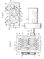
- FIGS 1 through 6 illustrate one embodiment of a chip cutting apparatus according-to the present invention, in which reference numeral 1 denotes a conveyor casing disposed in the vicinity of a machine tool (not shown) and within the conveyor casing 1 there is accommodated a takeout end of a chip conveyor 2 for conveying chips discharged out of the machine tool, which takeout end defines a lower takeout opening 3.
- reference numeral 4 is a pair of support arms of a substantially L-shaped cross sectiop having their re- spective one ends fixed to side plates 1-a of the conveyor casing 1 and their respective other ends adapted to support a cutting implement 5 thereon.
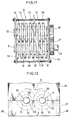
- the cutting implement 5 comprises, as illustrated in Figure 2 or 3, a rectangular frame 8 composed of a pair of opposed longitudinal frame members 6 and a pair of opposed lateral frame members 7, a pair of cutter shafts 9 and 10 each having a spline and rotatably supported within the rectangular frame 8 by means of bearings 11, and a plurality of alternately arranged cutters 12 and spacers 13 spline fitted and fixed around the cutter shafts 9 and 10 so that the cutters and spacers around one of the cutter shafts are closely opposed respectively to the spacers and cutters around the other cutter shaft.
- Each of the cutters 12 is formed of a disk to have a central spline hole 14 for snugly admitting the cutter shaft 9 or 10 and is provided on the circumference thereof with a pawl-shaped projection 15 formed by cutting and a relief portion 16 continuing to the projection 15 and extending substantially straightforward, as illustrated in Figure 5.
- Each of the spacers 13 is formed of a disk having a smaller diameter of that of the cutter 12 and having a central spline hole (not shown) similar to the spline hole 14 in the cutter 12.
- Reference numeral 19 stands for a dish-shaped shoot disposed at a position immediately below the takeout opening 3 of the chip conveyor 2 and mounted on support members 20 which are fixed one each to the pair of opposed longitudinal frame members 6 as is best shown in Figure 2.
- Denoted by 21 in Figure 1 or Figure 2 is a motor equipped with a deceleration 22 and having a drive shaft 23 connected to one of the cutter shafts through a coupling 24.
- numeral 25 depicts a chip box positioned below the cutting implement 5, 26 a motor disposed on the side of the takeout end of the conveyor 2, 27 a chain casing, and 28 a switch box.
- Numeral 29 in Figure 6 represents a chip being treated.
- each of scrapers 30 having an upper tapered surface 30a inclined downwardly and also having a lower corrugated engaging pawl 31 whose configuration conforms to a combined configuration of the alternately arranged cutters 12 and spacers 13 and which is brought into intimate contact sideways with the cutters 12 and spacers 13.
- the cutter 12 may be modified as shown in Figures 7(a) to 7(d).
- the portions of each of the cutter modifications identical with or similar to those of the cutter shown in Figure 5 are indicated by the same reference numerals as used in Figure 5.
- a pair of combinations each comprising a projection 15 and a relief portion 16 are symmetrically disposed relative to a central spline hole 14.
- a plurality of V-or U-shaped notches are formed, thereby allowing the corner portions to serve as projections 15 and the concave portions to function as relief portions 16.
- a cutter 12 is provided on the circumference thereof with four projections 15 and four relief portions 16 continuing to the corresponding projections 15 and extending substantially straightforward.
- Any of these modifications of the cutter 12 has a plurality of projections 15 and relief portions 16, thereby shortening the chip cutting cycle and enhancing the cutting efficiency.
- the projections 15 and the relief portions 16 of the cutters 12 around one of the cutter shafts 9 and 10 are arranged so as to be capable of slightly colliding radially inwardly with the cutters 12 around the other cutter shaft.
- FIGs 8 and 9 illustrate other cutting implements 5 usable in the present invention.
- the portions of each of these cutting implements identical with or similar to those of the cutting implement 5 of Figure 4 are indicated by the same reference numerals as used in Figure 4.
- the cutting implement 5 comprises two pairs of cutter shafts 9 and 10 disposed in two stages and cutters 12 and spacers 13 disposed in the same manner as described hereinbefore, whereby the chip cutting process is carried out in two stages to facilitate minuteness of the chips with high exactitude.
- the cutting implement 5 of Figure 9 is characterised in that a pair of rotatable rollers 32 are added to the cutting implement 5 of Figure 8 at a position below the lower pair of cutter shafts 9 and 10 for crushing the minutely cut chips to thereby further promote the minuteness of the chips.
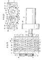
- Figure 10 shows a modification of the cutting apparatus, in which the cutting implement 5 shown in Figures 1 through 4, Figure 8 or Figure 9 is mounted on a movable rack33 within which the chip box 25 is accommodated, and the cutting implement 5 and a drive mechanism including the motor 21 are joined together into a unit.
- This movable type cutting apparatus can easily be installed without requiring work for attachment to a machine tool.
- Installation of the stationary cutting apparatus shown in Figures 1 to 4 is accomplished by locating the upper edgs of the shoot 19 at the edge of the takeout opening 3 of the conveyor casing 1, fixing the respective one ends of the support arms 4 to the side surface of the conveyor casing 1 and fixing the respective other ends of the support arms 4 to the frame 8 having the cutting implement 5, such as at the bottom surface thereof, for example.
- Installation of the movable type cutting apparatus shown in Figure 10 is achieved by moving the rack 33 to locate the shoot 19 at a position of the discharge edge of a machine tool to which chips are conveyed.
- Each of the cutting apparatuses having the constructions as described above is used by driving the motor 21 to transmit its power to one cutter shaft 9 associated with the drive shaft 23, thereby rotating the cutter shaft 9 and driving one gear 17 firmly attached to the end of the drive shaft 23, and driving the other gear 18 in engagement with the gear 17 by the drive force of the gear 17 to rotate the other cutter shaft 10 firmly attached to the other gear 18 in a direction opposite to the direction in which the cutter shaft 9 is rotated at the same speed as that of the cutter shaft 9.
- the chips 29 fall on the circumferential surfaces of the cutters 12 and the spacers 13 of the cutting implement which are driven as described above, they are urged to the inside circumferential surfaces of the cutters 12 and the spacers 13 by the frictional force generated therebetween.
- the inside circumferential surfaces of the cutters 12 and the spacers 13 are ordinarily in a substantially circumscribed state, the chips 29 continue their rolling on the circumferential surfaces of the cutters and the spacers without being drawn in the lower inside of the cutting implement 5. In this state, therefore, the chips 29 are not cut off.
- the relief portions 16 With the rotation of the cutters 12, the relief portions 16 are moved in the opposite direcitons toward the normal-line direction and the adjacent gaps 34 and 35 are directed as separated from each other. As a result, the chips 29 are curved along the peripheral edges of the relief portions 16 and become tense gradually.
- the adjacent gaps 34 and 35 are disposed back to back, and the chips 29 are corrugated along the peripheral surfaces of the cutters 12 and the spacers 13 to heighten their tension and are pushed against the fixed positions of the relief portions 16.
- the chips 29 thus cut into minute pieces fall into the chip box 25 and accommodated therewithin. Since the chips 29 within the chip box 25 are minutely cut into pieces, they do not bulk large and are easy to handle. By the use of the cutting implement shown in Figure 8 or 9, the chips 29 are more minutely cut into pieces or crushed. Therefore, the cutting treatment is effected with high exactitude and promoted, and discharge of the chips 29 not cut can be prevented effectively.
- the chip discharged out of a machine tool etc. can be cut into minute pieces, bulkiness of the chips can be eliminated and the chips are easy to handle and can be conveyed more easily as compared with the conventional conveyance of the chips produced and left intact. Further, the chips can be prevented from scattering in the conveyance thereof. Therefore, well-regulated working environment can be secured.
- the cutting apparatus since the cutting implement, shoot and motor are combined into an integral unit to reduce its installation area, the cutting apparatus may be practically used either in a stationary form by the attachment thereof to a prescribed position of a machine tool or in a movable form by the installation thereof on a rack.
- the movable type cutting apparatus can easily be installed relative to a preset or newly set machine tool.
- the installation space of the cutting apparatus of the present invention can be reduced.
- FIGS 11 through 30 show the second to fifth embodi- mentsof the cutting apparatus according to the present invention.
- the portions identical with or similar to those of the first embodiment are indicated by the same reference numerals as used in Figures 1 through5, and the description thereof is " omitted in the following.
- the cutting apparatus as the second embodiment of the present invention shown in Figure 11 is adapted to be combined integrally with the takeout end of the chip conveyor 2.
- the opposite side plates 1a of the conveyor casing 1 placed at the takeout end of the chip conveyor 2 are allowed to serve as the longitudinal frame members 6 of the cutting implement 5 in the first embodiment and connected to each other with connection levers 36, whereby the cutting implement 5 in the second embodiment is integrally attached to the conveyor casing 1 so as to be placed at a position immediately below the takeout end of the chip conveyor 2.
- An attaching mechanism for the cutting implement 5 can be constructed as illustrated in Figure 12, for example.
- a lower side plate 37 having semi-circular bearing notches 40 by means of fastening screws 38 so that the semi-circular bearing notches cooperate to form circles for admitting the cutter shafts 9 and 10, thereby making it easy to attach the cutting implement 5 to the preset conveyor 2.
- each of the side plates 1a has a substantially elliptical through hole 41 formed in the lower portion thereof and the through hole 41 is stopped up by a pair of side cover plates 42 which have holes 43 for admitting the cutter shafts 9 and 10.
- the cutting implement 5 can be taken out together with the side cover plates 42 by detaching the side cover plates 42 and, therefore, it can be maintained or repaired, if necessary, with high convenience.
- the cutter 12 may optionally be formed in the shape of a truncated cone to have its conical surface provided in the base portion thereof with a multiplicity of catch grooves 44 as illustrated in Figures 15 to 17.
- a plurality of such cutters 12 are fitted'around cutter shafts 9 and 10 respectively so that the cutters 12 around one of the cutter shafts are arranged in the direction opposite to the direction in which the cutters 12 around the other cutter shaft are arranged and that the cutters 12 around the two cutter shafts 9 and 10 are alternately disposed and brought into intimate contact with one another at their conical surfaces without use of any spacer 13, whereby chips are caught in catch grooves 44 with high exactitude, broken between the conical surfaces of the adjacently intimate cutters 12 and crushed under pressure therebetween.
- the cutting apparatus utilising these cutters has promoted its ability to cut and crush the chips.
- This ability can further be improved by providing each of the conical surfaces of the cutters 12 with a plurality of projections 45 and arranging the projections in mesh with one another, i.e. placing one projection 45 on one of the opposed conical surfaces between the projections 45 on the other conical surface, as illustrated in Figures 18(a) to 18(c).
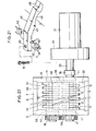
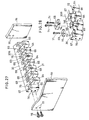
- FIG. 19 through 21 The third embodiment of the cutting apparatus according to the present invention is illustrated in Figures 19 through 21.
- "cutters 12 constituting a cutting implement 5 are formed in the shape of a substantial disk and each of these is provided in its plate surface with a plurality of semi-circular catch grooves 44. Between the axially adjacent cutters, there is interposed a spacer 13 having substantially the same thickness as that of the cutters 12 and a smaller diameter than that of the cutters. On each of the spacers 13, there is disposed a primary cutter 46 of a shape substantially the same as that of an ordinary cutting tool.
- the primary cutter 46 comprises a substantially L-shaped rectangular shank portion 47 and a sharp cutting edge portion 48 integrally formed with the leading'end of the shank portion 47 as shown in Figures 20 and 21:
- the lower surface of the shank portion 47 has a substantially arcuate concave 49 formed therein on its leading end side.
- the concave 49 is positioned immediately above the upper circumferential surface of the spacer 13 and the edge portion 48 is arranged in the vicinity of the circumferential surface of the cutter 12 opposed to the spacer 13.
- the primary cutter 46 is fixed to the upper end of a lateral frame member 7 by driving a bolt 51 into a bolt hole 50 bored in the rear end of the shank portion 47.
- reference numeral 52 denotes a groove formed in the upper end of the lateral frame member 7 at a position corresponding to the position of the spacer 13 for admit- tingthe rear end of the shank portion 47
- numeral 53 denotes a screw hole formed in the bottom of the groove 52.
- part of the chips is cut by the primary cutters 46 prior to the cutting by the cutters 12 to promote a high-precision cutting operation and, at the same time, the chips not cut are prevented from falling from gaps 54 between the opposed cutters 12 and spacers 13.
- the chips can be cut into minute pieces with high exactitude and high precision.
- a plurality of secondary platelike cutters 57 having substantially the same thickness as that of the cutters 12 are zigzag arranged below the gaps 54 between the opposed cutters 12 and spacers 13.
- Each of the secondary cutters 57 has its upper edge 55 disposed adjacent to the lower circumferential surface of the spacer 13 and its lower edge 56 disposed adjacent to the lower circumferential surface of the cutter 12 opposed to the spacer 13 and is attached to a groove 59 in a stationary'plate 58 by means of bolts 60 at the position of the corresponding cutter 12 and spacer 13 opposed to each other.
- these secondary cutters 57 and the stationary plate 58 may be integrally molded by a-molding method.
- reference numeral 61 represents a screw hole formed in the bottom of the groove 59
- numeral 62 depicts another screw hole bored in the end face of the stationary plate 58 so as to register with a screw hole (not shown) in the longitudinal frame member 6.
- a bolt 63 is driven into these screw holes for fixing the stationary plate 58 to the longitudinal frame member 6.
- the chips falling from the gaps 54 between the opposed cutters 12 and spacers 13 are received on inclined guide surfaces 64 between the upper edges 55 and the lower edges 56 of the secondary cutters 57 and allowed to slide thereon toward the lower edges 56, thereby cutting the chips with the cutters 12 in cooperation with the lower edges 56. Therefore, chip packing due to the narrowness of the gap 54, galling between the chips and the cutters 12, and loss of the drive force of the cutters 12 due to the galling can be eliminated, thereby making it permissible to widen the gaps 54 to some extent and making it possible to cut the chips smoothly.
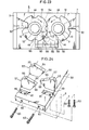
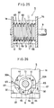
- FIGs 25 to 28 illustrate the fifth embodiment of the cutting apparatus according to the present invention, in which a single cutter shaft 9 is adopted.
- the cutter shaft 9 is disposed between the side plates la, coupled directly to a motor 21 and, provided thereabout with a plurality of cutters 12 and spacers 13 which are arranged alternately.
- Corrugated scrapers 30 are disposed on the opposite sides of a series of the alternately arranged cutters 12 and spacers 13.
- Engaging projections 64 and grooves 65 which constitute engaging pawls 31 of the scrapers 30 have notches 66 and 67 formed respectively therein.
- Chip cutters 68 and 69 are fixed within the notches 66 and 67 by means of bolts 70 and 71, respectively.
- the chip cutters 68 and 69 are substantially wedge- shaped.
- the chip cutter 69 is smaller in size than the chip cutter 68 and, as illustrated in Figure 26, the chip cutter 69 has its sharp edge positioned at a level substantially the same as the central axis of the cutter 12 and the chip cutter 68 has its sharp edge located at a level lower than the central axis of the spacer 13.
- reference numerals 72 and 73 denote screw holes formed respectively in the notches 66 and 67
- numerals 74 and 75 stand for fitting holes bored respectively in the chip cutters 68 and 69
- numeral 75 depicts screw holes formed in the side edge surface of the scraper 30
- numeral 77 represents through holes bored in the side plates 1a for snugly admitting bolts 78.
- chips supplied between the cutters 12 and chip cutters 69 and between the spacers 13 and chip cutters 68 can be cut into minute pieces by the chip cutters 68 and 69, thereby preventing the chips from slipping off and the so- called galling caused by the slipped chips from occurring and also preventing the motor associated with the cutter shaft 9 from being driven under overload.
- Means for preventing such an overload operation of the motor 21 may be constructed as illustrated in Figures 29 and 30.
- cutter shafts 9 and 10 have a plurality of cutters 12 and spacers 13 fitted alternately thereabouts in the axial direction so that the cutters around each of the cutter shafts are held in mesh with the opposed spacers 13, the cutter shaft 9 associated with the motor 21 has a small-diameter gear 17 fixed thereto and the other cutter shaft 10 has a large-diameter gear 18 fixed thereto so as to be engaged with the small-diameter gear 17.
- the torque of the small-diameter gear 17 given when the chips are cut and crushed can be reduced, thereby reducing the--load exerted on the motor 21 through the cutter shaft 9.
- the cutting apparatus of the present invention has been described as applied to the case where chips are cut and crushed. However, the present invention should not be limited to this case. It goes without saying that the present invention may be applied to a cutting apparatus or crusher for glass, wood, plastic, scraps discharged out of a press, for example.
Abstract
Description
- The present invention relates to a cutting apparatus adapted to cut swarf, cuttings and chips discharged out of a machine tool etc. into minute pieces.
- Generally, swarf, cuttings and chips (hereinafter referred to collectively as "chips") being discharged out of a machine tool such as a lathe etc. in a machining factory are scattered about the machine tool to deteriorate working environment and interrupt safety work. For this reason, workers are required to periodically remove the scattered chips for the purpose of eliminating the environmental deterioration and securing the safety work. However, since almost all of such chips are elongated and have a shape like a helical spring, these are difficult to handle and will bulk large soon. Even when the chips are thrown into a chip box or pit set within a workshop, for example, the chip box or pit is filled with the chips within a short period of time and the overflowing chips are scattered thereabouts to deteriorate the working environment again.
- Under the circumstances, there has been an increased demand for cutting apparatuses easy to handle and suitable for cutting chips into minute pieces. To satisfy the demand, there have heretofore been proposed various cutting apparatuses of this type. For example, German Patent No. 965,465 discloses a slitter comprising a pair of rotary shafts disposed in parallel with each other and a plurality of disklike cutter members disposed at prescribed intervals, snugly fitted around each of the rotary shafts, and each provided on the circumference of the cutter body thereof with a multiplicity of cutting edge projections so that the cutting edge projections of the cutter members around one of the rotary shafts are held in mesh with those of the gutter members around the other rotary shaft in a staggered fashion. Further, Japanese Utility Model Publication No. 55-41309 teaches a crusher wherein a plurality of disklike cutter members are disposed at prescribed intervals, snugly fitted around each of rotary shafts, each provided on the circumference of the cutter body thereof with multiplicity of claws, in place of the cutting edge projec :ons as in the aforementioned German Patent, for catchin objects being treated, so that the cutter members around one of the rotary shafts are arranged in mesh with and at the opposite side surfaces thereof in intimate contact wi; those around the other rotary shaft.
- In the former prior art device, however, since the crushing function can only be attained when the cutting edge projections mesh with each other, the crushing is effected intermittently and therefore, is undesirabl Further, in the latter prior art device, since the cutt bodies are provided on the circumferences thereof with the claws complicated in shape, it is difficult to produce the cutter members. Furthermore, in any of these prio: art devices, since a large gap is left between the leading end of the cutting edge projection or claw and a collar, there is a fair possibility of the objects under treatment coming out of the gap when the corresponding cutting edge projections or claws engage with each other, and since a irive source for rotating the cutter members is disposed soart from the casing, the device becomes large-scale as a mole and necessitates a large installation area.
- The present invention has been accomplished in view of the drawbacks suffered by the conventional tting devices as described above.'
- One object of the present invention is to provide a cutting- apparatus capable of preventing objects under cutting treatment from coming out of gaps between cutter members and of reducing its installation area.
- Another object of the present inventic is to provide a cutting apparatus capable of being easily attached to the takeout end of a chip conveyor for conveying chips discharged out of a machine tool.
- Still another object of the present invention is to provide a cutting apparatus capable of cutting objects under treatment into minute pieces with high exactitude and high precision.
- According to the present invention, there is provided a cutting apparatus comprising, as an integral unit, a pair of cutter shafts disposed substantially in parallel to each other, a motor attached to one of the cutter shafts for rotating the one cutter shaft, means for rotating the other cutter shaft in a direction opposite to the direction in which the one cutter shaft is rotated, a plurality of substantially disklike cutters fitted around each of the cutter shafts, a plurality of substantially disklike spacers fitted around each of the cutter shafts, the cutters and the spacers around each of the cutter shafts being alternately arranged and brought into intimate contact with each other in the axial direction of each of the cutter shafts, the cutters and the spacers around one of the cutter shafts being closely opposed respectively to the spacers and the cutters around the other cutter shaft so as to hold the cutters in mesh with the opposed spacers.
- Following is a description, by way of example only and with reference to the accompanying drawings, of apparatus for carrying the invention into effect. In the drawings:-
- Figure 1 is a schematic front view illustrating one embodiment of a cutting apparatus according to the present invention.
- Figure 2 is an enlarged cross-sectional view illustrating the principal part of the embodiment.
- Figure 3 is a plan view illustrating the principal part of the embodiment.
- Figure 4 is a front view illustrating a cutting implement used in the embodiment.
- Figure 5 is a front view illustrating a cutter constituting a part of the cutting implement.
- Figures 6(a) to 6(d) are explanatory views illustrating the cutting steps taken by the cutters in the order mentioned.
- Figures 7(a) to 7(d) are front views illustrating modifications of the cutter usable in the present invention.
- Figure 8 is a front view illustrating another cutting implement usable in the present invention.
- Figure 9 is a front view illustrating still another cutting implement usable in the present invention.
- Figure 10 is a partially sectioned front view illustrating a modification of the embodiment of Figure 1.
- Figure 11 is a plan view illustrating the principal part of a second embodiment of the cutting apparatus according to the present invention.
- Figure 12 is a front view illustrating a modification of the second embodiment.
- Figure 13 is a front view illustrating another modification of the second embodiment.
- Figure 14 is a cross-sectional view taken along line XIV - XIV in Figure 13.
- Figure 15 is a plan view illustrating another cutter usable in the present invention.
- Figure 16 is a front view illustrating the cutter of Figure 15.
- Figure 17 is a cross-sectional view taken along line XVII - XVII in
Fi gure 16. - Figures 18(a) to 18(c) are plan views illustrating modifications of the cutter of Figure 15.
- Figure 19 is a plan view illustrating a third embodiment of the cutting apparatus according to the present invention. ―
- Figure 20 is a front view illustrating the principal part of the third embodiment.
- Figure 21 is a perspective view illustrating the principal part of the third embodiment.
- Figure 22 is a bottom view illustrating a fourth embodiment of the cutting apparatus according to the present invention.
- Figure 23 is a front view illustrating the principal part of the fourth embodiment.
- Figure 24 is a perspective view illustrating the principal part of the fourth embodiment.
- Figure 25 is a plan view illustrating the principal part of a fifth embodiment of the cutting apparatus according to the present invention.
- Figure 26 is a partially sectioned front view illustrating'the principal part of the fifth embodiments
- Figures 27 and 28 are perspective views illustrating the principal part of the fifth embodiment.
- Figure 29 is a plan view illustrating a modification of the fifth embodiment.
- Figure 30 is a longitudinally sectioned view of Figure 29.
- The present invention will now be described with reference to the illustrated embodiments.
- Figures 1 through 6 illustrate one embodiment of a chip cutting apparatus according-to the present invention, in which
reference numeral 1 denotes a conveyor casing disposed in the vicinity of a machine tool (not shown) and within theconveyor casing 1 there is accommodated a takeout end of achip conveyor 2 for conveying chips discharged out of the machine tool, which takeout end defines alower takeout opening 3. Denoted bynumeral 4 is a pair of support arms of a substantially L-shaped cross sectiop having their re- spective one ends fixed to side plates 1-a of theconveyor casing 1 and their respective other ends adapted to support acutting implement 5 thereon. - The
cutting implement 5 comprises, as illustrated in Figure 2 or 3, arectangular frame 8 composed of a pair of opposedlongitudinal frame members 6 and a pair of opposedlateral frame members 7, a pair ofcutter shafts rectangular frame 8 by means ofbearings 11, and a plurality of alternately arrangedcutters 12 andspacers 13 spline fitted and fixed around thecutter shafts - Each of the
cutters 12 is formed of a disk to have acentral spline hole 14 for snugly admitting thecutter shaft shaped projection 15 formed by cutting and arelief portion 16 continuing to theprojection 15 and extending substantially straightforward, as illustrated in Figure 5. t - Each of the
spacers 13 is formed of a disk having a smaller diameter of that of thecutter 12 and having a central spline hole (not shown) similar to thespline hole 14 in thecutter 12. - To the corresponding ends of the
cutter shafts fixed gears Reference numeral 19 stands for a dish-shaped shoot disposed at a position immediately below thetakeout opening 3 of thechip conveyor 2 and mounted onsupport members 20 which are fixed one each to the pair of opposedlongitudinal frame members 6 as is best shown in Figure 2. Denoted by 21 in Figure 1 or Figure 2 is a motor equipped with adeceleration 22 and having adrive shaft 23 connected to one of the cutter shafts through acoupling 24. In Figure 1,numeral 25 depicts a chip box positioned below thecutting implement 5, 26 a motor disposed on the side of the takeout end of theconveyor 2, 27 a chain casing, and 28 a switch box. Numeral 29 in Figure 6 represents a chip being treated. Further, in Figure 4, each ofscrapers 30 having an uppertapered surface 30a inclined downwardly and also having a lower corrugatedengaging pawl 31 whose configuration conforms to a combined configuration of the alternately arrangedcutters 12 andspacers 13 and which is brought into intimate contact sideways with thecutters 12 andspacers 13. - The
cutter 12 may be modified as shown in Figures 7(a) to 7(d). The portions of each of the cutter modifications identical with or similar to those of the cutter shown in Figure 5 are indicated by the same reference numerals as used in Figure 5. In the modification of the cutter shown in Figure 7(a), a pair of combinations each comprising aprojection 15 and arelief portion 16 are symmetrically disposed relative to acentral spline hole 14. In other modifications shown in Figures 7(b) and 7(c), a plurality of V-or U-shaped notches are formed, thereby allowing the corner portions to serve asprojections 15 and the concave portions to function asrelief portions 16. In a further modification shown in Figure 7(d), acutter 12 is provided on the circumference thereof with fourprojections 15 and fourrelief portions 16 continuing to thecorresponding projections 15 and extending substantially straightforward. Any of these modifications of thecutter 12 has a plurality ofprojections 15 andrelief portions 16, thereby shortening the chip cutting cycle and enhancing the cutting efficiency. When thesecutters 12 are attached to thecutter shafts projections 15 and therelief portions 16 of thecutters 12 around one of thecutter shafts cutters 12 around the other cutter shaft. - Figures 8 and 9 illustrate other cutting implements 5 usable in the present invention. The portions of each of these cutting implements identical with or similar to those of the cutting implement 5 of Figure 4 are indicated by the same reference numerals as used in Figure 4. In Figure 8, the cutting implement 5 comprises two pairs of
cutter shafts cutters 12 andspacers 13 disposed in the same manner as described hereinbefore, whereby the chip cutting process is carried out in two stages to facilitate minuteness of the chips with high exactitude. The cutting implement 5 of Figure 9 is characterised in that a pair ofrotatable rollers 32 are added to the cutting implement 5 of Figure 8 at a position below the lower pair ofcutter shafts - Figure 10 shows a modification of the cutting apparatus, in which the cutting implement 5 shown in Figures 1 through 4, Figure 8 or Figure 9 is mounted on a movable rack33 within which the
chip box 25 is accommodated, and the cutting implement 5 and a drive mechanism including themotor 21 are joined together into a unit. This movable type cutting apparatus can easily be installed without requiring work for attachment to a machine tool. - Installation of the stationary cutting apparatus shown in Figures 1 to 4 is accomplished by locating the upper edgs of the
shoot 19 at the edge of thetakeout opening 3 of theconveyor casing 1, fixing the respective one ends of thesupport arms 4 to the side surface of theconveyor casing 1 and fixing the respective other ends of thesupport arms 4 to theframe 8 having the cutting implement 5, such as at the bottom surface thereof, for example. Installation of the movable type cutting apparatus shown in Figure 10 is achieved by moving therack 33 to locate theshoot 19 at a position of the discharge edge of a machine tool to which chips are conveyed. - Each of the cutting apparatuses having the constructions as described above is used by driving the
motor 21 to transmit its power to onecutter shaft 9 associated with thedrive shaft 23, thereby rotating thecutter shaft 9 and driving onegear 17 firmly attached to the end of thedrive shaft 23, and driving theother gear 18 in engagement with thegear 17 by the drive force of thegear 17 to rotate theother cutter shaft 10 firmly attached to theother gear 18 in a direction opposite to the direction in which thecutter shaft 9 is rotated at the same speed as that of thecutter shaft 9. With the rotation of thesecutter shafts cutters 12 andspacers 13 snugly fitted around one of thecutter shafts chips 29 into minute pieces. - When a machine tool is driven to start a cutting operation, the
chips 29 discharged out of the machine tool are conveyed by theconveyor 2 to fall from thetakeout opening 3 formed on the takeout side of theconveyor 2 onto the cutting implement 5. At this time, almost all of thechips 29 fall on the upper circumferential surfaces of thecutters 12 and thespacers 13. However, since the cutters and the spacers around each of thecutter shafts chips 29 passing through any of the fine gaps among the cutters and the spacers. Further, even when part of thechips 29 overflows on the side apart from the side on which thecutters 12 and thespacers 13 are opposed to each other, since the engagingpawls 31 of thescrapers 30 stop up the gaps between thecutters 12 and thespacers 13, it is possible to prevent thechips 29 from falling. - When the
chips 29 fall on the circumferential surfaces of thecutters 12 and thespacers 13 of the cutting implement which are driven as described above, they are urged to the inside circumferential surfaces of thecutters 12 and thespacers 13 by the frictional force generated therebetween. However, since the inside circumferential surfaces of thecutters 12 and thespacers 13 are ordinarily in a substantially circumscribed state, thechips 29 continue their rolling on the circumferential surfaces of the cutters and the spacers without being drawn in the lower inside of the cutting implement 5. In this state, therefore, thechips 29 are not cut off. - When the
cutters 12 are further rotated to allow theirrelief portions 16 to be adjacent to each other as shown in Figure 6(a), thechips 29 are caught and scooped by theprojections 15 to be moved from the inside circumferential surfaces of thecutters 12 onto therelief portions 16. As thecutters 12 are rotated, therelief portions 16 are allowed to gradually rise and consequently, as shown in Figure 6(b), there are formedgaps relief portion 16 and the opposed circumferential surface of thespacer 13 and between those in the adjacent row. As a result, thechips 29 are moved into thesegaps - With the rotation of the
cutters 12, therelief portions 16 are moved in the opposite direcitons toward the normal-line direction and theadjacent gaps chips 29 are curved along the peripheral edges of therelief portions 16 and become tense gradually. When therelief portions 16 are kept upright, as shown in Figure 6(c), theadjacent gaps chips 29 are corrugated along the peripheral surfaces of thecutters 12 and thespacers 13 to heighten their tension and are pushed against the fixed positions of therelief portions 16. - When the
cutters 12 are rotated further from the aforementioned state, theprojections 15 engage with thechips 29 as shown in Figure 6(d), with the result that thechips 29 are further strained and pushed downwardly by theprojections 15 and then cut off. Thus, a plurality of cut pieces having a length substantially the same as the thickness of the edges of thecutters 12 fall into the lower inside of the cutting implement 5. - The
chips 29 thus cut into minute pieces fall into thechip box 25 and accommodated therewithin. Since thechips 29 within thechip box 25 are minutely cut into pieces, they do not bulk large and are easy to handle. By the use of the cutting implement shown in Figure 8 or 9, thechips 29 are more minutely cut into pieces or crushed. Therefore, the cutting treatment is effected with high exactitude and promoted, and discharge of thechips 29 not cut can be prevented effectively. - According to the present invention, as described above, since the chip discharged out of a machine tool etc. can be cut into minute pieces, bulkiness of the chips can be eliminated and the chips are easy to handle and can be conveyed more easily as compared with the conventional conveyance of the chips produced and left intact. Further, the chips can be prevented from scattering in the conveyance thereof. Therefore, well-regulated working environment can be secured.
- Furthermore, in the first embodiment of the cutting apparatus according to the present invention, since the cutting implement, shoot and motor are combined into an integral unit to reduce its installation area, the cutting apparatus may be practically used either in a stationary form by the attachment thereof to a prescribed position of a machine tool or in a movable form by the installation thereof on a rack. The movable type cutting apparatus can easily be installed relative to a preset or newly set machine tool. In addition, the installation space of the cutting apparatus of the present invention can be reduced.
- Figures 11 through 30 show the second to fifth embodi- mentsof the cutting apparatus according to the present invention. The portions identical with or similar to those of the first embodiment are indicated by the same reference numerals as used in Figures 1 through5, and the description thereof is"omitted in the following.
- The cutting apparatus as the second embodiment of the present invention shown in Figure 11 is adapted to be combined integrally with the takeout end of the
chip conveyor 2. To be specific, theopposite side plates 1a of theconveyor casing 1 placed at the takeout end of thechip conveyor 2 are allowed to serve as thelongitudinal frame members 6 of the cutting implement 5 in the first embodiment and connected to each other with connection levers 36, whereby the cutting implement 5 in the second embodiment is integrally attached to theconveyor casing 1 so as to be placed at a position immediately below the takeout end of thechip conveyor 2. - An attaching mechanism for the cutting implement 5 can be constructed as illustrated in Figure 12, for example. To each of the
side plates 1a havingsemi-circular bearing notches 39 is detachably connected alower side plate 37 havingsemi-circular bearing notches 40 by means of fastening screws 38 so that the semi-circular bearing notches cooperate to form circles for admitting thecutter shafts preset conveyor 2. In the case shown in Figures 13 and 14, each of theside plates 1a has a substantially elliptical throughhole 41 formed in the lower portion thereof and the throughhole 41 is stopped up by a pair ofside cover plates 42 which haveholes 43 for admitting thecutter shafts side cover plates 42 by detaching theside cover plates 42 and, therefore, it can be maintained or repaired, if necessary, with high convenience. - The
cutter 12 may optionally be formed in the shape of a truncated cone to have its conical surface provided in the base portion thereof with a multiplicity ofcatch grooves 44 as illustrated in Figures 15 to 17. 'Specifically, a plurality ofsuch cutters 12 arefitted'around cutter shafts cutters 12 around one of the cutter shafts are arranged in the direction opposite to the direction in which thecutters 12 around the other cutter shaft are arranged and that thecutters 12 around the twocutter shafts spacer 13, whereby chips are caught incatch grooves 44 with high exactitude, broken between the conical surfaces of the adjacentlyintimate cutters 12 and crushed under pressure therebetween. Thus, the cutting apparatus utilising these cutters has promoted its ability to cut and crush the chips. This ability can further be improved by providing each of the conical surfaces of thecutters 12 with a plurality ofprojections 45 and arranging the projections in mesh with one another, i.e. placing oneprojection 45 on one of the opposed conical surfaces between theprojections 45 on the other conical surface, as illustrated in Figures 18(a) to 18(c). - The third embodiment of the cutting apparatus according to the present invention is illustrated in Figures 19 through 21. In this embodiment, "
cutters 12 constituting a cutting implement 5 are formed in the shape of a substantial disk and each of these is provided in its plate surface with a plurality ofsemi-circular catch grooves 44. Between the axially adjacent cutters, there is interposed aspacer 13 having substantially the same thickness as that of thecutters 12 and a smaller diameter than that of the cutters. On each of thespacers 13, there is disposed aprimary cutter 46 of a shape substantially the same as that of an ordinary cutting tool. - The
primary cutter 46 comprises a substantially L-shapedrectangular shank portion 47 and a sharpcutting edge portion 48 integrally formed with the leading'end of theshank portion 47 as shown in Figures 20 and 21: The lower surface of theshank portion 47 has a substantially arcuate concave 49 formed therein on its leading end side. The concave 49 is positioned immediately above the upper circumferential surface of thespacer 13 and theedge portion 48 is arranged in the vicinity of the circumferential surface of thecutter 12 opposed to thespacer 13. Theprimary cutter 46 is fixed to the upper end of alateral frame member 7 by driving abolt 51 into abolt hole 50 bored in the rear end of theshank portion 47. In Figures 20 and 21,reference numeral 52 denotes a groove formed in the upper end of thelateral frame member 7 at a position corresponding to the position of thespacer 13 for admit- tingthe rear end of theshank portion 47, and numeral 53 denotes a screw hole formed in the bottom of thegroove 52. - According to the third embodiment described above, part of the chips is cut by the
primary cutters 46 prior to the cutting by thecutters 12 to promote a high-precision cutting operation and, at the same time, the chips not cut are prevented from falling fromgaps 54 between theopposed cutters 12 andspacers 13. Thus, the chips can be cut into minute pieces with high exactitude and high precision. - The fourth embodiment of the cutting apparatus according to the present invention will be described with reference to Figures 22 to 24. In this embodiment, a plurality of secondary
platelike cutters 57 having substantially the same thickness as that of thecutters 12 are zigzag arranged below thegaps 54 between theopposed cutters 12 andspacers 13. Each of thesecondary cutters 57 has itsupper edge 55 disposed adjacent to the lower circumferential surface of thespacer 13 and itslower edge 56 disposed adjacent to the lower circumferential surface of thecutter 12 opposed to thespacer 13 and is attached to agroove 59 in astationary'plate 58 by means ofbolts 60 at the position of thecorresponding cutter 12 andspacer 13 opposed to each other. Optionally, thesesecondary cutters 57 and thestationary plate 58 may be integrally molded by a-molding method. In Figure 24,reference numeral 61 represents a screw hole formed in the bottom of thegroove 59, and numeral 62 depicts another screw hole bored in the end face of thestationary plate 58 so as to register with a screw hole (not shown) in thelongitudinal frame member 6. Abolt 63 is driven into these screw holes for fixing thestationary plate 58 to thelongitudinal frame member 6. - According to the fourth embodiment, the chips falling from the
gaps 54 between theopposed cutters 12 andspacers 13 are received on inclined guide surfaces 64 between theupper edges 55 and thelower edges 56 of thesecondary cutters 57 and allowed to slide thereon toward thelower edges 56, thereby cutting the chips with thecutters 12 in cooperation with the lower edges 56. Therefore, chip packing due to the narrowness of thegap 54, galling between the chips and thecutters 12, and loss of the drive force of thecutters 12 due to the galling can be eliminated, thereby making it permissible to widen thegaps 54 to some extent and making it possible to cut the chips smoothly. - Figures 25 to 28 illustrate the fifth embodiment of the cutting apparatus according to the present invention, in which a
single cutter shaft 9 is adopted. Thecutter shaft 9 is disposed between the side plates la, coupled directly to amotor 21 and, provided thereabout with a plurality ofcutters 12 andspacers 13 which are arranged alternately.Corrugated scrapers 30 are disposed on the opposite sides of a series of the alternately arrangedcutters 12 andspacers 13. Engagingprojections 64 andgrooves 65 which constitute engagingpawls 31 of thescrapers 30 havenotches Chip cutters notches bolts 70 and 71, respectively. - The
chip cutters chip cutter 69 is smaller in size than thechip cutter 68 and, as illustrated in Figure 26, thechip cutter 69 has its sharp edge positioned at a level substantially the same as the central axis of thecutter 12 and thechip cutter 68 has its sharp edge located at a level lower than the central axis of thespacer 13. In Figure 28,reference numerals notches numerals chip cutters scraper 30, and numeral 77 represents through holes bored in theside plates 1a for snugly admittingbolts 78. - According to the fifth embodiment of the present invention, chips supplied between the
cutters 12 andchip cutters 69 and between thespacers 13 andchip cutters 68 can be cut into minute pieces by thechip cutters cutter shaft 9 from being driven under overload. - Means for preventing such an overload operation of the
motor 21 may be constructed as illustrated in Figures 29 and 30. To be specific, whilecutter shafts cutters 12 andspacers 13 fitted alternately thereabouts in the axial direction so that the cutters around each of the cutter shafts are held in mesh with the opposedspacers 13, thecutter shaft 9 associated with themotor 21 has a small-diameter gear 17 fixed thereto and theother cutter shaft 10 has a large-diameter gear 18 fixed thereto so as to be engaged with the small-diameter gear 17. With this construction, the torque of the small-diameter gear 17 given when the chips are cut and crushed can be reduced, thereby reducing the--load exerted on themotor 21 through thecutter shaft 9. - The cutting apparatus of the present invention has been described as applied to the case where chips are cut and crushed. However, the present invention should not be limited to this case. It goes without saying that the present invention may be applied to a cutting apparatus or crusher for glass, wood, plastic, scraps discharged out of a press, for example.
Claims (11)
Applications Claiming Priority (8)
| Application Number | Priority Date | Filing Date | Title |
|---|---|---|---|
| JP1984133480U JPS6225321Y2 (en) | 1984-08-31 | 1984-08-31 | |
| JP133480/84U | 1984-08-31 | ||
| JP173551/84U | 1984-11-15 | ||
| JP17355184U JPS6189451U (en) | 1984-11-15 | 1984-11-15 | |
| JP26476284A JPS61141946A (en) | 1984-12-15 | 1984-12-15 | Cutter |
| JP264762/84 | 1984-12-15 | ||
| JP1985045284U JPH0314253Y2 (en) | 1985-03-28 | 1985-03-28 | |
| JP45284/85U | 1985-03-28 |
Publications (3)
| Publication Number | Publication Date |
|---|---|
| EP0174148A2 true EP0174148A2 (en) | 1986-03-12 |
| EP0174148A3 EP0174148A3 (en) | 1988-02-03 |
| EP0174148B1 EP0174148B1 (en) | 1990-05-09 |
Family
ID=27461668
Family Applications (1)
| Application Number | Title | Priority Date | Filing Date |
|---|---|---|---|
| EP85306060A Expired - Lifetime EP0174148B1 (en) | 1984-08-31 | 1985-08-27 | Cutting apparatus |
Country Status (3)
| Country | Link |
|---|---|
| US (1) | US4691871A (en) |
| EP (1) | EP0174148B1 (en) |
| DE (1) | DE3577514D1 (en) |
Cited By (10)
| Publication number | Priority date | Publication date | Assignee | Title |
|---|---|---|---|---|
| EP0239104A2 (en) * | 1986-03-27 | 1987-09-30 | H.S.M. Pressen GmbH | Cutting mechanism for a document shredder |
| EP0291774A2 (en) * | 1987-05-16 | 1988-11-23 | Alois Pöttinger Maschinenfabrik GmbH | Shredder with rotating knives |
| DE9108230U1 (en) * | 1991-07-04 | 1991-09-05 | Bannwarth, Roland, 7860 Schopfheim, De | |
| WO1991014501A1 (en) * | 1990-03-21 | 1991-10-03 | Per Torp | An apparatus for reducing materials |
| WO1993025312A1 (en) * | 1992-06-12 | 1993-12-23 | Erema Engineering Recycling Maschinen Und Anlagen Gesellschaft M.B.H. | Device for plasticising thermoplastic material |
| DE4236121A1 (en) * | 1992-10-27 | 1994-04-28 | Hermann Schwelling | Pre-shredding and dosing device, especially for large plants for the destruction of files and. waste materials |
| EP0730908A1 (en) * | 1995-03-10 | 1996-09-11 | Südrohrbau GmbH & Co. | Shredder |
| US5921372A (en) * | 1997-05-02 | 1999-07-13 | Environmental Products Corporation | Multiple chambered container compaction assembly with diverter |
| WO2002034396A1 (en) * | 1999-06-11 | 2002-05-02 | Horai Co., Ltd. | Rotary crusher |
| CN112827587A (en) * | 2020-12-29 | 2021-05-25 | 浙江财经大学 | Medicinal material rubbing crusher with blade shredding function |
Families Citing this family (31)
| Publication number | Priority date | Publication date | Assignee | Title |
|---|---|---|---|---|
| US5071080A (en) * | 1990-02-27 | 1991-12-10 | Fellowes Manufacturing Company | Document shredding machine |
| WO1991017690A1 (en) * | 1990-05-18 | 1991-11-28 | Szombathy Janos J | A machine for shredding vehicle tires and other articles |
| US5094392A (en) * | 1990-05-18 | 1992-03-10 | Szombathy Janos J | Machine for shredding vehicle tires and other articles |
| US5169075A (en) * | 1991-04-01 | 1992-12-08 | Galanty William B | Crushing device |
| US5295633A (en) * | 1992-01-13 | 1994-03-22 | Fellowes Manufacturing Company | Document shredding machine with stripper and cutting mechanism therefore |
| US5465822A (en) * | 1992-03-16 | 1995-11-14 | Environmental Products Corporation | Commodity densification assembly having a multiple path distribution device |
| US5427321A (en) * | 1992-07-03 | 1995-06-27 | Meiden Plant Engineering & Construction Co., Ltd. | Waste paper processing system |
| US5676321A (en) * | 1995-04-03 | 1997-10-14 | Fellowes Mfg. Co. | Cutting disk |
| US5636801A (en) * | 1995-08-02 | 1997-06-10 | Fellowes Mfg. Co. | One piece molded stripper for shredders |
| US5655725A (en) * | 1995-08-24 | 1997-08-12 | Fellowes Manufacturing Co. | Retaining plate for gearing |
| US5829697A (en) * | 1995-08-24 | 1998-11-03 | Fellowes Manufacturing Company | Support for cylinders in a paper shredder |
| US5961059A (en) * | 1997-04-30 | 1999-10-05 | Fellowes Manufacturing Company | Support for drive system in a paper shredder |
| US5826809A (en) * | 1997-04-30 | 1998-10-27 | Fellowes Manufacturing Company | Support for cutting cylinders in a paper shredder |
| US5954280A (en) * | 1998-05-12 | 1999-09-21 | Fellowes Manufacturing Company | Top blocker for a paper shredder |
| DE10037108A1 (en) * | 2000-07-27 | 2002-02-21 | Emmerich Tetkov | Cutting device to chop up vegetable matter has counter-cutter in form of circumferential cutter of rotatable second circular disk |
| FR2812565A1 (en) * | 2000-08-01 | 2002-02-08 | S M P In Pere & Fils Fa | Grinding component for plastic waste grinder |
| DE20201236U1 (en) * | 2001-10-18 | 2002-08-29 | Heissenberger & Pretzler Gmbh | comminution device |
| US6742731B2 (en) | 2002-03-19 | 2004-06-01 | Inter-Source Recovery Systems | System and method of shredding wet chips in a flume |
| CN100579659C (en) * | 2002-03-25 | 2010-01-13 | 阿尔皮尼特专利应用机构 | Crushing device |
| PL1620252T3 (en) * | 2003-04-27 | 2016-04-29 | Hermann Schwelling | Device for pressing empty containers together and method therefor |
| DE10325368B4 (en) * | 2003-04-27 | 2006-03-02 | Hermann Schwelling | Device for squeezing empty containers |
| US7467755B2 (en) * | 2003-07-01 | 2008-12-23 | Inter-Source Recovery Systems, Inc. | Parts separator apparatus and method of shredding |
| US7028935B2 (en) * | 2003-07-01 | 2006-04-18 | Inter-Source Recovery Systems, Inc. | Apparatus and method for shredding wet chip materials |
| DE102004052969B4 (en) * | 2003-10-30 | 2007-01-11 | Metso Lindemann Gmbh | Method for controlling the process of a crusher for material of any kind |
| WO2005079991A1 (en) * | 2004-02-19 | 2005-09-01 | Kabushiki Kaisha Kinki | Shear-type crusher and shear-type crushing method |
| US7380736B2 (en) * | 2005-05-04 | 2008-06-03 | Inter-Source Systems, Inc. | In-line shredder apparatus and method for shredding materials |
| US7287308B1 (en) | 2006-04-27 | 2007-10-30 | Xerox Corporation | Swarf cutter |
| EP2087937A1 (en) * | 2008-02-09 | 2009-08-12 | Shred-Tech Corporation | Side rail for a shredder with embedded fingers |
| US9968944B2 (en) | 2013-03-15 | 2018-05-15 | Inter-Source Recovery Systems | Parts separator |
| WO2016049120A1 (en) * | 2014-09-24 | 2016-03-31 | Jwc Enviornmental | High flow high capture side rails for comminutor |
| JP6867171B2 (en) * | 2017-01-12 | 2021-04-28 | 株式会社Subaru | Manufacturing method for boring tools and honeycomb parts |
Citations (12)
| Publication number | Priority date | Publication date | Assignee | Title |
|---|---|---|---|---|
| DE72294C (en) * | L. GENEVOIS in Neapel, Via Olivetta 30 | Chopping machine for fat, meat and the like | ||
| DE965465C (en) * | 1953-04-03 | 1957-06-06 | Friedrich Hermanns | Roller cutting machine for chopping oil-containing fruits, such as coconuts, palm kernels or the like. |
| FR2073746A5 (en) * | 1969-12-10 | 1971-10-01 | Bohmter Maschf | |
| FR2233470A1 (en) * | 1973-06-18 | 1975-01-10 | Testut Aequitas | Large scale waste disposal unit - has cooperating blades on rotary cylinder and pivoting door within duct |
| DE2526650A1 (en) * | 1975-06-14 | 1976-12-30 | Wilhelm Haeberle | Shredder for plastic scrap - with staggered counter rotating toothed cutter blades rotating at different speeds |
| US4046324A (en) * | 1973-06-22 | 1977-09-06 | Chambers Joseph W | Solid waste comminutor |
| GB1558423A (en) * | 1978-03-03 | 1980-01-03 | Dresser Europe Sa | Shredding machine |
| GB2059804A (en) * | 1979-10-16 | 1981-04-29 | Sant Andrea Novara Officine | Comminuting machine |
| US4275849A (en) * | 1973-05-25 | 1981-06-30 | Chambers William M | Macerator |
| EP0037036A2 (en) * | 1980-03-25 | 1981-10-07 | Lindemann Maschinenfabrik GmbH | Rotary shredding machine for the reduction of waste material |
| US4374573A (en) * | 1979-05-08 | 1983-02-22 | Rouse Michael W | Apparatus for shredding rubber tires and other waste materials |
| US4394983A (en) * | 1981-03-02 | 1983-07-26 | Kaca Corporation | Tire and refuse shredder |
Family Cites Families (4)
| Publication number | Priority date | Publication date | Assignee | Title |
|---|---|---|---|---|
| US4125228A (en) * | 1977-10-17 | 1978-11-14 | Garbalizer Corporation Of America | Shredder and improvements therein |
| JPS5541309A (en) * | 1978-09-14 | 1980-03-24 | Babcock Hitachi Kk | Corrosion preventing method of water wall pipe |
| US4385732A (en) * | 1980-08-29 | 1983-05-31 | Williams Robert M | Waste material breaking and shredding apparatus |
| US4489897A (en) * | 1983-03-02 | 1984-12-25 | General Binding Corporation | Apparatus for shredding documents |
-
1985
- 1985-08-27 EP EP85306060A patent/EP0174148B1/en not_active Expired - Lifetime
- 1985-08-27 DE DE8585306060T patent/DE3577514D1/en not_active Expired - Fee Related
- 1985-08-30 US US06/771,130 patent/US4691871A/en not_active Expired - Lifetime
Patent Citations (12)
| Publication number | Priority date | Publication date | Assignee | Title |
|---|---|---|---|---|
| DE72294C (en) * | L. GENEVOIS in Neapel, Via Olivetta 30 | Chopping machine for fat, meat and the like | ||
| DE965465C (en) * | 1953-04-03 | 1957-06-06 | Friedrich Hermanns | Roller cutting machine for chopping oil-containing fruits, such as coconuts, palm kernels or the like. |
| FR2073746A5 (en) * | 1969-12-10 | 1971-10-01 | Bohmter Maschf | |
| US4275849A (en) * | 1973-05-25 | 1981-06-30 | Chambers William M | Macerator |
| FR2233470A1 (en) * | 1973-06-18 | 1975-01-10 | Testut Aequitas | Large scale waste disposal unit - has cooperating blades on rotary cylinder and pivoting door within duct |
| US4046324A (en) * | 1973-06-22 | 1977-09-06 | Chambers Joseph W | Solid waste comminutor |
| DE2526650A1 (en) * | 1975-06-14 | 1976-12-30 | Wilhelm Haeberle | Shredder for plastic scrap - with staggered counter rotating toothed cutter blades rotating at different speeds |
| GB1558423A (en) * | 1978-03-03 | 1980-01-03 | Dresser Europe Sa | Shredding machine |
| US4374573A (en) * | 1979-05-08 | 1983-02-22 | Rouse Michael W | Apparatus for shredding rubber tires and other waste materials |
| GB2059804A (en) * | 1979-10-16 | 1981-04-29 | Sant Andrea Novara Officine | Comminuting machine |
| EP0037036A2 (en) * | 1980-03-25 | 1981-10-07 | Lindemann Maschinenfabrik GmbH | Rotary shredding machine for the reduction of waste material |
| US4394983A (en) * | 1981-03-02 | 1983-07-26 | Kaca Corporation | Tire and refuse shredder |
Cited By (13)
| Publication number | Priority date | Publication date | Assignee | Title |
|---|---|---|---|---|
| EP0239104A2 (en) * | 1986-03-27 | 1987-09-30 | H.S.M. Pressen GmbH | Cutting mechanism for a document shredder |
| EP0239104A3 (en) * | 1986-03-27 | 1988-08-03 | Hermann Schwelling | Cutting mechanism for a document shredder |
| EP0291774A2 (en) * | 1987-05-16 | 1988-11-23 | Alois Pöttinger Maschinenfabrik GmbH | Shredder with rotating knives |
| EP0291774A3 (en) * | 1987-05-16 | 1989-08-30 | Alois Pottinger Maschinenfabrik Gmbh | Shredder with rotating knives |
| WO1991014501A1 (en) * | 1990-03-21 | 1991-10-03 | Per Torp | An apparatus for reducing materials |
| DE9108230U1 (en) * | 1991-07-04 | 1991-09-05 | Bannwarth, Roland, 7860 Schopfheim, De | |
| WO1993025312A1 (en) * | 1992-06-12 | 1993-12-23 | Erema Engineering Recycling Maschinen Und Anlagen Gesellschaft M.B.H. | Device for plasticising thermoplastic material |
| DE4236121A1 (en) * | 1992-10-27 | 1994-04-28 | Hermann Schwelling | Pre-shredding and dosing device, especially for large plants for the destruction of files and. waste materials |
| EP0730908A1 (en) * | 1995-03-10 | 1996-09-11 | Südrohrbau GmbH & Co. | Shredder |
| US5921372A (en) * | 1997-05-02 | 1999-07-13 | Environmental Products Corporation | Multiple chambered container compaction assembly with diverter |
| WO2002034396A1 (en) * | 1999-06-11 | 2002-05-02 | Horai Co., Ltd. | Rotary crusher |
| CN112827587A (en) * | 2020-12-29 | 2021-05-25 | 浙江财经大学 | Medicinal material rubbing crusher with blade shredding function |
| CN112827587B (en) * | 2020-12-29 | 2022-03-15 | 浙江财经大学 | Medicinal material rubbing crusher with blade shredding function |
Also Published As
| Publication number | Publication date |
|---|---|
| DE3577514D1 (en) | 1990-06-13 |
| US4691871A (en) | 1987-09-08 |
| EP0174148B1 (en) | 1990-05-09 |
| EP0174148A3 (en) | 1988-02-03 |
Similar Documents
| Publication | Publication Date | Title |
|---|---|---|
| EP0174148A2 (en) | Cutting apparatus | |
| US4607800A (en) | Solid waste comminution machine | |
| US5680999A (en) | Shredder | |
| CA1071604A (en) | Comminuting apparatus | |
| EP0016063B1 (en) | Cutter in shredding machine | |
| WO2014045599A1 (en) | Cutting debris crushing device, cutting debris crushing blade, and cutting debris crushing data collection method in said cutting debris crushing device | |
| JP2813572B2 (en) | Cutting blade for shredder | |
| JP2003135989A (en) | Crusher of resin bumper for vehicle | |
| CN210333786U (en) | Descaling machine convenient to blank transmission | |
| CN205128090U (en) | Special kneader is destroyed to abandonment invoice | |
| JPH0230198Y2 (en) | ||
| EP0758573B1 (en) | Diamond grinding tool for surface machining of natural or artificial stone | |
| CN111231176A (en) | Tire slabbing machine | |
| JPH0141555Y2 (en) | ||
| JPH0314253Y2 (en) | ||
| CN211249318U (en) | Scrap iron recycling device for machining | |
| JPH0230029Y2 (en) | ||
| JPH0143174Y2 (en) | ||
| SU1313566A1 (en) | Arrangement for crushing chips in metal-cutting machine | |
| JPS6016474Y2 (en) | Cutting waste processing equipment | |
| GB2198681A (en) | Paper shredding apparatus | |
| KR200241464Y1 (en) | Screw cutting machine of pipe | |
| KR200274687Y1 (en) | cutting cutter for binding fruit | |
| JPS6225321Y2 (en) | ||
| JPH0748338Y2 (en) | Peeling machine |
Legal Events
| Date | Code | Title | Description |
|---|---|---|---|
| PUAI | Public reference made under article 153(3) epc to a published international application that has entered the european phase |
Free format text: ORIGINAL CODE: 0009012 |
|
| AK | Designated contracting states |
Kind code of ref document: A2 Designated state(s): DE FR GB |
|
| PUAL | Search report despatched |
Free format text: ORIGINAL CODE: 0009013 |
|
| AK | Designated contracting states |
Kind code of ref document: A3 Designated state(s): DE FR GB |
|
| 17P | Request for examination filed |
Effective date: 19880705 |
|
| 17Q | First examination report despatched |
Effective date: 19881212 |
|
| GRAA | (expected) grant |
Free format text: ORIGINAL CODE: 0009210 |
|
| AK | Designated contracting states |
Kind code of ref document: B1 Designated state(s): DE FR GB |
|
| REF | Corresponds to: |
Ref document number: 3577514 Country of ref document: DE Date of ref document: 19900613 |
|
| ET | Fr: translation filed | ||
| PLBE | No opposition filed within time limit |
Free format text: ORIGINAL CODE: 0009261 |
|
| STAA | Information on the status of an ep patent application or granted ep patent |
Free format text: STATUS: NO OPPOSITION FILED WITHIN TIME LIMIT |
|
| 26N | No opposition filed | ||
| PGFP | Annual fee paid to national office [announced via postgrant information from national office to epo] |
Ref country code: FR Payment date: 19970613 Year of fee payment: 13 |
|
| PGFP | Annual fee paid to national office [announced via postgrant information from national office to epo] |
Ref country code: GB Payment date: 19970814 Year of fee payment: 13 |
|
| PGFP | Annual fee paid to national office [announced via postgrant information from national office to epo] |
Ref country code: DE Payment date: 19971030 Year of fee payment: 13 |
|
| PG25 | Lapsed in a contracting state [announced via postgrant information from national office to epo] |
Ref country code: GB Free format text: LAPSE BECAUSE OF NON-PAYMENT OF DUE FEES Effective date: 19980827 |
|
| GBPC | Gb: european patent ceased through non-payment of renewal fee |
Effective date: 19980827 |
|
| PG25 | Lapsed in a contracting state [announced via postgrant information from national office to epo] |
Ref country code: FR Free format text: LAPSE BECAUSE OF NON-PAYMENT OF DUE FEES Effective date: 19990430 |
|
| PG25 | Lapsed in a contracting state [announced via postgrant information from national office to epo] |
Ref country code: DE Free format text: LAPSE BECAUSE OF NON-PAYMENT OF DUE FEES Effective date: 19990601 |
|
| REG | Reference to a national code |
Ref country code: FR Ref legal event code: ST |