EP0237682A1 - Système de contrôle pour appareil reproduisant des informations optiques - Google Patents
Système de contrôle pour appareil reproduisant des informations optiques Download PDFInfo
- Publication number
- EP0237682A1 EP0237682A1 EP86310026A EP86310026A EP0237682A1 EP 0237682 A1 EP0237682 A1 EP 0237682A1 EP 86310026 A EP86310026 A EP 86310026A EP 86310026 A EP86310026 A EP 86310026A EP 0237682 A1 EP0237682 A1 EP 0237682A1
- Authority
- EP
- European Patent Office
- Prior art keywords
- signal
- power supply
- control system
- circuit
- producing
- Prior art date
- Legal status (The legal status is an assumption and is not a legal conclusion. Google has not performed a legal analysis and makes no representation as to the accuracy of the status listed.)
- Granted
Links
Images


Classifications
-
- G—PHYSICS
- G11—INFORMATION STORAGE
- G11B—INFORMATION STORAGE BASED ON RELATIVE MOVEMENT BETWEEN RECORD CARRIER AND TRANSDUCER
- G11B19/00—Driving, starting, stopping record carriers not specifically of filamentary or web form, or of supports therefor; Control thereof; Control of operating function ; Driving both disc and head
- G11B19/20—Driving; Starting; Stopping; Control thereof
- G11B19/28—Speed controlling, regulating, or indicating
-
- G—PHYSICS
- G11—INFORMATION STORAGE
- G11B—INFORMATION STORAGE BASED ON RELATIVE MOVEMENT BETWEEN RECORD CARRIER AND TRANSDUCER
- G11B7/00—Recording or reproducing by optical means, e.g. recording using a thermal beam of optical radiation by modifying optical properties or the physical structure, reproducing using an optical beam at lower power by sensing optical properties; Record carriers therefor
- G11B7/08—Disposition or mounting of heads or light sources relatively to record carriers
- G11B7/085—Disposition or mounting of heads or light sources relatively to record carriers with provision for moving the light beam into, or out of, its operative position or across tracks, otherwise than during the transducing operation, e.g. for adjustment or preliminary positioning or track change or selection
- G11B7/08505—Methods for track change, selection or preliminary positioning by moving the head
-
- G—PHYSICS
- G11—INFORMATION STORAGE
- G11B—INFORMATION STORAGE BASED ON RELATIVE MOVEMENT BETWEEN RECORD CARRIER AND TRANSDUCER
- G11B7/00—Recording or reproducing by optical means, e.g. recording using a thermal beam of optical radiation by modifying optical properties or the physical structure, reproducing using an optical beam at lower power by sensing optical properties; Record carriers therefor
- G11B7/08—Disposition or mounting of heads or light sources relatively to record carriers
- G11B7/09—Disposition or mounting of heads or light sources relatively to record carriers with provision for moving the light beam or focus plane for the purpose of maintaining alignment of the light beam relative to the record carrier during transducing operation, e.g. to compensate for surface irregularities of the latter or for track following
- G11B7/0946—Disposition or mounting of heads or light sources relatively to record carriers with provision for moving the light beam or focus plane for the purpose of maintaining alignment of the light beam relative to the record carrier during transducing operation, e.g. to compensate for surface irregularities of the latter or for track following specially adapted for operation during external perturbations not related to the carrier or servo beam, e.g. vibration
Definitions
- the prosent invention relates to a control system for optical disc information reproducing apparatus, and more particularly to a control system for a moving device such as disc rotation drive motors, pickup transfer drive motors, pickup lens focusing or tracking actuators of optical disc players such as digital audio disc plyers, video diso players or memory disc apparatus.
- a moving device such as disc rotation drive motors, pickup transfer drive motors, pickup lens focusing or tracking actuators of optical disc players such as digital audio disc plyers, video diso players or memory disc apparatus.
- optical record discs which store optically recorded information data or signals such es digitized audio signals, video or image signals and any other information data and optical record disc reproducing apparatus for reproducing the recorded information data.
- the optical record disca of such type for example, compact discs (CD) (a type of digital audio disca), optical video disca, optical image discs and the like are so arranged that digital data intended for high density recording are recorded in the fora of pit strings forming a spiral track or plurality of concentric tracks on one aide of the optical diso and reproduced through reading the pit strings by means of transducer means like an optical pickup device using laser beams during a rotation of the optical rocord disc at a predetermined velocity.
- CD compact discs
- optical video disca a type of digital audio disca
- optical image discs and the like are so arranged that digital data intended for high density recording are recorded in the fora of pit strings forming a spiral track or plurality of concentric tracks on one aide of the optical diso and reproduced through reading the pit strings by
- the disc reproducing apparatus are provided with a rotation drive motor for rotating the optical disc at the predetermined velocity.
- the rotation drive motor drives compact discs at a constant linear velocity (CLV).
- the rotation drive motor of the video disc players drives video discs at a constant angular velocity (CAV).
- the rotation velocities of the disc rotation drive motors are controlled to keep the CLV or CAV velocity in constant in the disc reproducing operation.
- the rotation velocity can be maintained to keep the predetermined CLV or CAV state with a relatively low power consumption during the normal disc reproducing operation. There, however, is required a relatively large power consumption for bringing the disc rotation drive motors from a stop state to the predetermined velocity state or vice versa at a start to the disc reproducing operation or at an interruption to a reproducing stop state.
- the disc reproducing apparatus alto is provided-with a pickup transfer drive motor for transfering the optical pickup in the radial direction of the optical discs.
- the transfer speed of the pickup transfer drive motor is controlled at a relatively low speed in the disc reproducing operation. Therefor the transfer speed at that time can be maintained in constant with a relatively low power consumption.
- the optical pickup device is transferred at a relatively high speed from one position to another position at a long distance track search operation, the reproducing start operation and the reproducing stop operation. At the operations, there is required a relatively large power consumption for bringing the pickup transfer drive motor from the low speed transfer state to the high speed transfer state or vice versa.
- the disc reproducing apparatus also is provided in the optical pickup device a lens, a focusing actuator and a tracking actuator.
- the lens places the laser beam on the record disc.
- the focusing actuator drives the lens in the perpendicular direction of the optical disc or the longitudinal direction of the light beam for controlling a focus of the laser beam on the optical disc.
- the tracking actuator drivea the lens in the radial direction of the optical disc or the perpendicular direction of the light beam for controlling the laser beam to follow the track of the optical disc.
- the actuators adjust or shift a location of the lens in a relatively narrow distance range with a relatively low power consumption at the ordinary reproducing operation. While the actuators are required to shift the lens in a relatively wide distance range to make the laser beam focus or track on a given track of the optical disc at the short distance track search operation, the reproducing start operation and the reproducing stop operation. At the operations, there is required a relatively large power consumption for the actuators to shift the lens in the wide distance range.
- the actuators are required to fail for shifting the lens at an occurence of failures of the information data pickup, e.g., signal dropouts in the optical pickup device. At that time, it is required that the actuators are given a power leas than the power at the normal disc reproducing operation.
- the moving devices such as the disc rotation drive motor or the like are servo controlled by some servo control signal obtained from the reproduced information data through the optical pickup device for keeping the optical disc or the like in a proper state of the rotation velocity or the like during the normal disc reproducing operation.
- a tracking error signal e.g., a tracking error signal
- a focusing error signal e.g., a focusing error signal
- a synchronous control signal aaa an automatic frequency control (AFC) signal
- AFC automatic frequency control
- the moving devices While at a prescribed state such as the start operation, the search operation or the like, the moving devices are controlled by some other signal for compelling the prescribed stato, such as a start command signal given from an operation control section or a signal indicating an abnormal in the servo control aignal. Then a power supply for the moving devices are controlled by the servo control signal or the compelling signal.
- the power supply for driving the moving devices popularly is performed in the field of the portable disc players by using a PWM (pulse width modulation) technique.
- PWM pulse width modulation
- an electric power W at driving the load by a pulse width modulation (PWM) signal is expressed by the following equation: where R la the resistance of the load, and E le the effective voltage of the PWM signal.
- Figure 1 is a graph showing the waveform of the PWM signal.
- the effective voltage E becomes as follows.
- Eo is a direct current (DC) component.
- the power conversion efficiency can be obtained by obtaining the ratio (Eo / E) of the DC component Eo and the effective voltage E.
- the effective voltage E is a function of ⁇ / T, that is, the ratio (hereinafter called as duty ratio) of the ON time period or the pulse width ⁇ of the PWM signal and the cycle T of the PWM signal. It is clear that the power conversion efficiency depends on the duty ratio.
- Figure 2 is a diagram showing the charaoteristic of the power conversion efficiency to the duty ratio when the PWM signal of the carrier frequency 44.1 kHz at the peak value of 1 V is applied to a load with the resistance R.
- the pulse width ⁇ is varied while the cycle T of the PWM signal is made constant, thereby to change the duty ratio.
- the solid line shows the actually measured value of the power conversion efficiency characteristic
- PWM signals having the largest duty ratio in PWM signals with the same effective voltage is used to drive a load, e.g., the moving device like the disc rotation drive motor.
- PWM signals are required that they have a fairly high effective voltage sufficient to make the moving device move at a high speed at the prescribed operation such as the start of the disc reproducing operation as described above. From this purpose, it is also necessary to set the peak value of a PWM signal as high as possible.
- PWM signals normally are applied to motors after amplified through some amplifiers.
- the peak value of the PWM signal is therefore inevitably determined by the power supply voltage applied to the amplifier in the conventional disc reproducing apparatus.
- the PWM signal is oblidged to have a relatively low duty ratio in the normal reproducing operation state so that the moving device moves the optical discs with a relatively large power consumption.
- an object of the present invention la to provide a control system for optical information reproducing apparatus which is able to a drive moving device of the reproducing apparatus with a relatively low power consumption.
- Another object of the present invention is to provide a control system for optical information reproducing apparatus which is able to drive a moving device of the reproducing apparatus with a relatively high power conversion efficiency from the electric energy to the kinetic energy.
- a further object of the present invention is to provide a control system for optical information reproducing apparatus which is able to drive a rotation drive motor of the reproducing apparatus for an optical disc with a relatively low power consumption or a relatively high power conversion efficiency from the electric energy to the kinetic energy, at a prescribed disc control state aa well as at a normal disc reproducing operation state.
- a further object of the present invention is to provide a control system for optical information reproducing apparatus which is able to drive a transfer drive motor for an optical pickup of the reproducing apparatus with a relatively low power consumption or a relatively high power -conversion efficiency from the electric energy to the kinetic energy, at a prescribed pickup control state as well as at a normal disc reproducing operation state.
- a further object of the present invention is to provide a control system for optical information reproducing apparatus which is able to drive a focusing actuator for a laser beam control lens of the reproducing apparatus with a relatively low power consumption or a relatively high power conversion efficiency from the electric energy to the kinetic energy, at a prescribed focusing actuator control state as well as at a normal disc reproducing operation state.
- a further object of the present invention is to provide a control system for optical information reproducing apparatus which is able to drive a tracking actuator for a laser beam control lens of the reproducing apparatus with a relatively low power consumption or a relatively high power conversion efficiency from the electric energy to the kinetic energy, at a prescribed tracking actuator control state as well as at a normal disc reproducing operation state.
- one aspect of the control system for optical information reproducing apparatus in which information data stored in an optical disc is read out during a rotation of the optical disc by a light spot of a light beam, includes a light beam source such as a semiconductor laser beam device, a moving device such as a turntable for rotatably supporting the optical disc, a device responsive to the light beam reflected from the optical disc such as a photoelectric transducers the photoelectric transducer producing an electrical signal corresponding to the information data, a circuit for deriving a servo control signal from the reproduced signal such as a tracking error signal producing circuit, a circuit for modulating the servo control signal to a pulse width modulation (PWM) signal, a drive device such as a motor responsive to the PWM signal for driving the moving device, a source for producing a response control signal, and a circuit for applying the drive with a power supply voltage which is changeable in response to the response control signal.
- PWM pulse width modulation
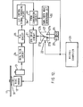
- Figure 4 shows a block diagram of a compact disc player.
- the compact disc player is provided with a power supply circuit using the PWM technique.
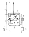
- an optical disc 11 is supported on a turntable 10.
- the turntable 10 is provided rotatably to a disc motor 12.
- an optical pickup 13 ia provided movably in the radial direction of the optical disc 11.
- the optical pickup 13 is transferred by a pickup transfer motor 14 in the radial direction of the optical disc 11.
- a symbolically represented optical pickup device 13 is movably supported on a feeder 13a.
- the feeder 13a is driven by a pickup transfer motor 14 as described later so that optical pickup device 13 moves radially in reference to the surface of the optical disc 11.
- the optical pickup 13 comprises a carriage 13b, a source of a light beam, e.g., a semiconductor laser device 13c, a collimater lens 13d, a semi-transparent mirror 1 3e, a device for placing a laser beam LB on the optical disc 11, e.g., a objective lens 13f, a split photosensor 13g, a tracking actuator 13h and a focusing actuator 13i.
- the laser device 13c radiates the laser beam LB.
- the collimater lens 1 3d, the semi-transparent mirror 13e and the objective lena 13f guides the laser beam LB to the optical disc 11 so that the laser beam LB is placed on the optical disc 11 in a form of light spot.
- the optical pickup 13 then scans concentric tracks of the optical disc 11 one after another or a spiral track of the optical disc 11 with the light spot of the laser beam LB, in moving radially in a direction of an arrow A in the drawing during the disc reproducing operation.
- the laser beam LB is reflected by the optical disc 11 and then applied to the split photosensor 13g through the objective lens 13f and the semi-transparent mirror 13e.
- the split photosensor 13g detects from the reflected laser beam LB information data responding to a state, e.g., a etrength of the reflected laser beam LB and produces an electrical signal responding to the information.
- the objective lene 13f is movably mounted on the carriage 13b of the optical pickup 13.
- the tracking actuator 13h controls a position of objective lens 13f in the radial direction of the optical disc 11 so that the light spot of the laser beam LB follows a center of a prescribed track in, e.g., the reproducing operation.
- the tracking control of the objective lens 13f may be made by a tracking control system as follows, like a conventional one.
- the focusing actuator 131 controls the position of objective lens 13f in the perpendicular direction to the surface of the optical disc 11 so that the laser beam LB is accurately focused its light spot on a prescribed track in, e.g., the reproducing operation.
- the focusing control of the objective lens 13f also may be made by a focusing control system as follows, like a conventional one.
- a reproduced signal is obtained from the optical pickup 13 in the diso reproducing operation.
- the reproduced signal is applied to a tracking error signal producing circuit 15 and a tracking error signal TE corresponding to the tracking shift of the objective lena 13f (see Figure 5) provided in the optical pickup 13 is produced.
- This tracking error signal TE is applied to the tracking actuator 13h (see Figure 5) for moving the objective lens 13f in the optical pickup 13 in the radial direction of the optical disc 11 through a drive circuit 16 to perform a tracking servo control.
- the tracking error signal TE is applied to a low-pass filter circuit 17, and after that high frequency components of the tracking error signal TE are removed.
- the tracking error signal TE is applied to a pulse width modulation (PWM) conversion circuit 19 through an adder 18.
- PWM conversion circuit 19 produces a pulse width modulation (PWM) signal by comparing the level of the tracking error signal TE outputted from the low-pass filter circuit 17 with a reference saw-tooth wave signal which is outputted from a aaw-tooth wave generation circuit 20. Therefore, the tracking error signal TE is converted to a pulse signal, i.e., the PWM signal which has a pulse width responding to the level of the tracking error signal TE.
- the PWM signal for the normal disc reproducing operation la applied to a balanced transformerless (BTL) drive circuit 2 1 .
- the BTL drive circuit 21 amplifies the peak level of the PWM signal up to a power supply voltage applied from a selectable power supply circuit 22 aa described later.
- the amplified PWM signal is applied to the pickup transfer drive motor 14.
- the pickup transfer drive motor 14 controls the transfer speed of the optical pickup 13.
- the optical pickup 13 is transferred at a relatively low speed corresponding to the disc reproducing operation in the radial direction of the optical disc 11.
- a long distance search operation command data corresponding to the distance and the direction for moving the optical pickup 13 to a prescribed position on the optical disc 11 at a high speed is generated from an operation control circuit sueh as a microcomputer 23.
- the search operation command data is applied to a transfer compelling signal generation circuit 24.
- the transfer compelling signal generation circuit 24 generates a transfer compelling signal corresponding to the search operation command data.
- the transfer compelling signal is applied to the PWM conversion circuit 19 through the adder 18, thereby to produce a PWM signal which has a pulse width responding to the level of the transfer compelling signal.
- the PWM signal for the search operation has a pulse width responding to the level of the transfer compelling signal.
- the PWM signal is amplified through the BTL drive circuit 21 and then applied to the pickup transfer drive motor 14.
- the pickup transfer drive motor 14 controls the transfer speed of the optical pickup 13.
- the optical pickup 13 is transferred at a relatively high speed corresponding to the search operation in the radial direction of the optical disc 11 to perform the track jump.
- the search operation command signal is applied to the selectable power supply circuit 22.
- the selectable power supply circuit 22 is comprised of a first and second power supply sources 25 and 26 and a controllable selector switch 27.
- the first power supply source 25 produces a first power supply voltage V1.
- the second power supply source 26 produces a second power supply voltage V2 which is higher than the first power supply voltage V1.
- These power supply sources 25 and 26 are connected to a first and second fixed contact 27a and 27b of the controllable selector switch 27.
- a common contact 27c of the controllable selector switch 27 is connected to the power supply input terminal of the BTL drive circuit 21. The common contact 27c is selectively connected to the first and the second fixed contact 27a and 27b.
- the common contact 27c is connected to the first fixed contact 27a through a selecter blade 27d. Accordingly, the first power supply voltage V1 is applied to the BTL drive circuit 21 together with the PWM signal converted from the tracking error signal TE.
- the common contact 27c is connected to the first fixed contact 27a through the aelecter blade 27d.
- the second power supply source 26 is selected to a connection to the controllable selector switch 27 so that the second power source voltage V2 is applied to the BTL drive circuit 21 together with the PWM signal converted from the transfer compelling signal for the search operation.
- the second power supply voltage V2 is applied to the BTL drive circuit 21.
- the peak level of the amplified PWM signal outputted from the BTL drive circuit 21 has a relatively high level, i.e., the second power eupply voltage V2.
- the duty ratio of the amplified PWM signal for the search operation is held in an appropriate value. This allows the pickup transfer drive motor 14 to be driven with an appropriate power conversion efficiency.
- the first power supply voltage VI ia applied to the BTL drive circuit 21 in a reproducing condition of the optical disc 11.
- the peak level of the amplified PWM signal outputted from the BTL drive circuit 21 is restrained in a relatively low level, i.e., the first power supply voltage VI.
- the duty ratio of the amplified PWM signal for the normal disc reproducing operation is increased.This allows the pickup transfer drive motor 14 to be driven in the highly power conversion efficiency.
- the duty ratio of the PWM signal for the normal disc reproducing operation can be set to the duty ratio of the PWM signal for the search operation by adjusting the first and second power supply voltages V1 and V2 to each other.
- the optical pickup control system for the compact disc player can drive the optical pickup at the high transfer speed with the higher effective voltage in the search operation. And also the system can drive the optical pickup at the low transfer speed with the sufficient power conversion efficiency in the normal disc reproducing operation. As a result, the compact disc player can operate with the relatively small power consumption.
- FIG. 6 shows the detailed construction of the B TL drive circuit 21 in Figure 4.
- the signal input terminal 28 is directly connected to control input terminals of first and second switches 30 and 31.
- the signal input terminal 2 8 is connected to control input terminals of third and fourth switches 32 and 33 through an inverter 29.
- the PWM signals applied to the third and fourth switches 32 and 33 are opposite in phase to the PWM signals applied to the first and second switches 30 and 31.
- the first and third switches 30 an 32 are connected in series between a power supply voltage input terminal 34 which is connected to the selectable power supply circuit 22 and a ground terminal.
- the second and fourth switches 31 an 33 also are connected in series between the power supply voltage input terminal 34 and a ground terminal.
- the PWM signal with the peak level V1 as shown by the solid line in Figure 7 is applied to the load resistance R.
- the PWM signal of the peak value V2 as shown by the broken line in Figure 7 is applied to the load 14.
- the dynamic range of the BTL drive circuit 21 can be enlarged and its gain can be increased. This results in the transfer control of the optical pickup 13 becoming more effective both at the relatively low speed in the normal disc reproducing operation and at the relatively high speed in the search operation.
- FIG 8 a second embodiment of the present invention will described.
- the second embodiment shown in Figure 8 is also the compact disc player according to the present invention and is different from the first embodiment shown in Figure 4 in followings. Thus, the differences from the first embodiment will be described here for the simplicity of explanation.
- a reproduced signal outputted from the optical pickup 13 is applied to a data slice circuit 34 and therein the signal is shaped its waveform to a rectangular pulse.
- the signal outputted from the data slice circuit 34 is applied to a phase looked loop (PLL) circuit 35 and therein a synchronization signal is extracted from the reproduced signal.
- PLL phase looked loop
- the synchronization signal outputted from the PLL circuit 30 is applied to a CLV servo control signal producing circuit 36 and therein an automatic frequency control (AFC) signal for a CLV rotation frequency servo control of the disc rotation drive motor 12 and an automatic phase control (APC) signal for a CLV rotation phase servo control of the disc rotation drive motor 12 are produced.
- AFC automatic frequency control
- APC automatic phase control
- the AFC and the APC signals produced from the CLV servo control signal producing circuit 36 is applied to the PWM conversion circuit 19. Further an abnormal AFC detection circuit 37 is connected between the CLV servo control signal producing circuit 36 and the selectable power supply circuit 22.
- the AFC signal outputted from the CLV servo control signal producing circuit 36 has a relatively low value so that the disc rotation drive motor 12 rotates with a relatively small power gain.
- the PLL circuit 35 tails to extract the synchronization signal.
- the AFC signal produced from the CLV servo control signal producing circuit 36 increaaes to an abnormal value larger than the value in the normal disc reproducing operation.
- the abnormal AFC detecting circuit 37 detects the abnormal AFC signal and then controls the selectable power supply circuit 22.
- the selectable power supply circuit 22 then applies the higher second power supply voltage V2 to the BTL drive circuit 2 1 .
- the disc rotation drive control system of the second embodiment according to the present invention can bring the disc rotation motor 12 in to the prescribed CLV rotation state with the high power conversion efficiency.
- FIG 9 a third embodiment of the present invention will described.
- the third embodiment shown in Figure 9 is also the compact disc player according to the preaent invention and is different from the second embodiment shown in Figure 8 in followings. Thus, the differences from the second embodiment will be described here for the simplicity of explanation.
- an abnormal synchronization detection circuit 38 is connected between the PLL circuit 35 and the selectable power supply circuit 22.
- the synchronization signal outputted from the PLL circuit 35 has a relatively low value so that the disc rotation drive motor 12 rotates with a relatively small power gain.
- the PLL circuit 35 fails to extract the synchronization signal.
- the synchronization signal produced from the PLL circuit 35 increases to an abnormal value larger than the value in the normal disc reproducing operation.
- the abnormal synchronization detecting circuit 38 detects the abnormal synchronization signal and then controls the selectable power supply circuit 22.
- the selectable power supply circuit 22 then applies the higher second power supply voltage V2 to the BTL drive circuit 21.
- FIG 10 a fourth embodiment of the present invention will described.
- the fourth embodiment shown in Figure 10 is also the compact disc player according to the present invention and is different from the first embodiment shown in Figure 4 in followings. Thus, the differences from the first embodiment will be described here for the simplicity of explanation.
- a detector 39 responsive to a mechanical shock is provided and connected to the selectable power supply circuit 22.
- the tracking error signal TE outputted from the tracking error signal signal producing circuit 15 has a relatively low value.
- the tracking actuator 13h shifts the objective lens 13f in the radial direction of the optical disc 11 at the relatively slow speed so that the light spot of the laser beam LB well follows the prescribed track.
- the detector 39 produces a detection signal in response to the mechanical shock. The detection signal is applied to the selectable power supply circuit 22.
- the selectable power supply circuit 22 then applies the higher second power supply voltage V2 to the BTL drive circuit 21.
- the PWM signal converted from, the tracking error signal T E is amplified to the level of the second power supply voltage V 2 .
- the tracking actuator 13h is then driven by the PWM signal which has a higher voltage than that in the normal tracking operation.
- the tracking actuator 1 3h can quickly shift the objective lens so that the light spot of the laser beam LB restores on the prescribed track with the high power conversion efficiency.
- FIG 11 a fifth embodiment of the present invention will described.
- the fifth embodiment shown in Figure 11 is also the compact disc player according to the preaent Invention and is different from the fourth embodiment shown in Figure 10 in followings. Thus, the differences from the fourth embodiment will be described here for the simplicity of explanation.
- a focusing error signal producing circuit 40 is provided in place of the tracking error signal producing circuit 15 in Figure 10.
- the BTL drive circuit 21 is connected to the focusing actuator 13i (see Figure 5).
- a focusing error signal FE outputted from the focusing error signal signal producing circuit 40 has a relatively low value so that the focusing actuator 131 shifts the objective lens 13f in the longitudinal direction of the surface of the optical disc 11 at the relatively slow speed so that the light spot of the laser beam LB is well focused to the surface of the optical disc 11.
- the focusing actuator 131 fails to foous the light spot to the surface of the optical track 11. The light spot then can be easily outfooused a relatively long distance from the surface of the optical track 11.
- the detector 39 produoes a detection signal in response to the mechanical shock.
- the detection signal is applied to the selectable power supply circuit 22.
- the selectable power supply circuit 22 then applies the higher second power supply voltage V2 to the BTL drive circuit 21.
- the PWM signal converted from the focusing error signal FE is amplified to the level of the second power supply voltage V2.
- the focusing actuator 13i is then driven by the P WM signal which has a higher voltage than that in the normal foousing operation.
- the focusing actuator 1 3i can quiokly shift the objective lena so that the light spot of the laser beam LB is focused on the aurface of the optical disc 11 with the high power conversion efficiency.
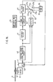
- FIG 12 a sixth embodiment of the present invention will described.
- the sixth embodiment shown in Figure 12 is also the compact disc player according to the present invention and is different from the second embodiment shown in Figure 8 in followings. Thus, the differences from the second embodiment will be described here for the simplicity of explanation.
- the microcomputer 23 is connected to the CLV servo control signal producing circuit 36 as well as the selectable power supply circuit 22.
- the synchronization signal outputted from the PLL circuit 35 has a relatively low value so-that the disc rotation drive motor 12 rotates with a relatively small power gain.
- the microcomputer 23 produces a a stop operation command signal of a high (H) level signal.
- the stop operation command signal is applied to both the CLV servo control signal producing circuit 36 and the selectable power supply circuit 22.
- the CLV servo control signal producing circuit 36 produces a signal which operates to damp the the rotation of the disc drive motor 12.
- the damping signal is converted to the PWM signal in the PWM conversion circuit 19.
- the selectable power supply circuit 22 applies the second power supply voltage V2 to the BTL drive circuit 21. Therefore, the PWM signal converted from the damping signal is amplified its peak level to the second power supply voltage V2 in the BTL drive circuit 21.
- the amplified PWM signal converted from the damping- signal is appled to the disc rotation drive motor 12 so that the disc rotation drive motor 12 is damped its rotation quickly.
- the disc reproducing stop control system of the sixth embodiment according to the present invention can bring the disc rotation drive motor 12 or the turntable 1 0 into stop condition quickly and with the high power conversion efficiency.
- FIG 13 a seventh embodiment of the present invention will described.
- the seventh embodiment shown in Figure 13 is also the compact disc player according to the present invention and is different from the first embodiment shown in Figure 4 in followings. Thus, the differences from the first embodiment will be described here for the simplicity of explanation.
- the BTL circuit 21 is connected to the tracking actuator 1 3h of the optical pickup 13. While, the microcomputer 23 is connected to only the selectable power supply circuit 22.
- the tracking error signal TE outputted from the tracking error signal producing circuit 15 has a relatively low value.
- the tracking actuator 13h shifts the objective lens 13f in the radial direction of the optical disc 11 at the relatively slow speed so that the light spot of the laser beam LB well follows the prescribed track.
- a track jump for a relatively short distance is commanded to the tracking actuator 13h for, e.g., a short distance search operation, a short distance search operation command signal corresponding to the distance and the direction for moving the tracking actuator 13h to a prescribed position on the optical disc 11 at a high speed ia generated from the microcomputer 23.
- the short distance search operation command signal is applied to the selectable power supply circuit 22.
- the selectable power supply circuit 22 thus applies the second power supply voltage V2 to the BTL drive circuit 21 so that the PWM aignal converted from the tracking error signal TE is amplified to the second power supply voltage V2.
- the tracking actuator 13h kicks the objective lens 13f in the radial direction of the optical disc 11 at a relatively fast speed, As a result, the objective lens 13f is shifted at the relatively fast speed corresponding to the short distance search operation in the radial direction of the optical disc 11 to perform the short distance track jump.
- FIG 14 a eighth embodiment of the present invention will described.
- the eighth empodiment shown in Figure 14 is also the compact disc player according to the present invention and is different from the seventh embodiment shown in Figure 13 in followings. Thus, the differences from the first embodlment will be described here for the simplicity of explanation.
- a focusing error signal producing circuit 40 is provided in place of the tracking error signal producing circuit 15 in Figure 13.
- the BTL drive circuit 21 is connected to the focusing actuator 13i (see Figure 5).
- the objective lens 13f is settled at a prescribed position.
- the focusing actuator 131 shifts the objective lens 13f in the perpendicular direction to the surface of the optical disc 1 1 toward a the proper position so that the light spot of the laser beam LB is well focused on the surface of the optical disc 11.
- the focusing error signal producing circuit 40 produces the focusing error signal FE of a relatively high level.
- the high level focusing error signal FE is converted to the PWM signal in the PWM conversion circuit 19 and the applied to the BTL drive circuit 21. While the microcomputer 23 producee the reproducing operation command signal of a high level.
- the reproducing operation command signal is applied to the selectable power supply circuit 22.
- the selectable power supply circuit 22 thus applies the second power supply voltage V2 to the BTC drive Circuit 21 so that the PWM signal converted from the focusing error signal FE is amplified to the second power supply voltage V2.
- the focusing actuator 13i kicks the objective lens 13f in the perpendicular direction to the surface of the optical disc 11 at a relatively fast speed.
- the objective lens 13f is shifted quickly and with the high power conversion efficiency to the proper position so that the light spot of the laser beam LB is well focused on the surface of the optical disc 11.
- FIG 15 a ninth embodiment of the present invention will described.
- the ninth embodiment shown in Figure 15 is also the compact disc player according to the present invention and is different from the fourth embodiment shown in Figure 10 in followings.
- a detector 41 is connected to the optical pickup 13 to receive the reproduced signal.
- the detector 41 is further connected to the tracking error producing circuit 15 to receive the tracking error signal TE.
- the detector 41 is connected its output terminal to the selectable power supply circuit 22.
- the selectable power supply circuit 22 has a third power supply source 42 in place of the second power supply source 26 as well as the first power supply source 26.
- the third power supply source 42 produces a third power supply voltage V3 which is lower than the first power supply voltage V1.
- the optical pickup 13 produces the reproduced signal corresponding to the recorded information of the optical disc 11 .
- the tracking error signal signal producing circuit 15 produces the tracking error signal TE of a relatively low level.
- the selectable power supply circuit 22 applies the first power supply voltage V1 to the BTL drive circuit 21.
- the optical pickup 13 traces an inferior portion of the optical disc 11 such as a portion damaged by dust or a flaw, the optical pickup 13 fails to produce the reproduced signal or produces the reproduced signal of a very high level.
- the tracking error signal producing circuit 15 produces the tracking error signal TE of a relatively high level.
- the detector 41 produces a high level signal in response to both the high level tracking error signal TE and the lack of the reproduced signal or the reproduced slgnal of the excessivee level.
- the high level signal is applied to the selectable power supply circuit 22.
- the selectable power supply circuit 22 then applies the third power supply voltage V3 to the BTL drive circuit 21.
- the PWM signal converted from the tracking error signal TE is amplified its peak level to the level of the third power supply voltage V3.
- the tracking actuator 13h is then driven by the PWM signal which has a lower voltage than that in the normal tracking operation.
- the tracking actuator 13h is then decreased its power gain to drive.
- the tracking actuator control according to the embodiment can operate with the high power conversion efficiency at the normal reproducing operation as well as at the tracing of the inferior portion of the optical disc 11.
- FIG 16 a tenth embodiment of the present invention will described.
- the tenth embodiment shown in Figure 16 is also the compact disc player according to the present invention and is different from the ninth embodiment shown in Figure 15 in followings. Thus, the differences from the first embodiment will be described here for the simplicity of explanation.
- a focusing error signal producing circuit 40 is provided in place of the tracking error signal producing circuit 15 in Figure 15 .
- the BTL drive circuit 21 is connected to the focusing actuator 13i (see Figure 5).
- the optical pickup 13 produces the reproduced signal corresponding to the recorded information of the optical disc 11. While, the focusing error signal signal producing circuit 40 produces the focusing error signal FE of a relatively low level.
- the selectable power supply circuit 22 applies the first power supply voltage V1 to the BTL drive circuit 21.
- the optical pickup 13 traces the inferior portion of the optical disc 11, the optical pickup 13 fails to produce the reproduced signal or produces the reproduced signal of a very high level.
- the focusing error signal producing circuit 15 produces the tracking error signal TE of a relatively high level.
- the detector 41 produces a high level signal in response to both the.high level tracking error signal TE and the lack of the reproduced signal or the reproduced signal of the excessive level.
- the high level signal is applied to the selectable power supply circuit 22.
- the selectable power supply circuit 22 then applies the third power supply voltage V3 to the BTL drive circuit 21.
- the PWM signal converted from the focusing error signal FE is amplified its peak level to the level of the third power supply voltage V3.
- the focusing actuator 131 is then driven by the PWM signal which has a lower voltage than that in the normal focusing operation.
- the focusing actuator 131 is then decreased its power gain to drive.
- the objective lens 13f is held in the position that the focusing actuator 13i has focused the light spot of the laser beam LB to the surface of the optical disc 11 before tracing the inferior portion.
- the focusing actuator control according to the embodiment can operate with the high power conversion efficiency at the normal reproducing operation as well as at the tracing of the inferior portion of the- optical disc 11.
Applications Claiming Priority (20)
| Application Number | Priority Date | Filing Date | Title |
|---|---|---|---|
| JP29132185A JPS62150534A (ja) | 1985-12-24 | 1985-12-24 | トラツキング制御装置 |
| JP291319/85 | 1985-12-24 | ||
| JP291320/85 | 1985-12-24 | ||
| JP29131885A JPS62150573A (ja) | 1985-12-24 | 1985-12-24 | トラツキング制御装置 |
| JP29131985A JPS62150532A (ja) | 1985-12-24 | 1985-12-24 | フオ−カス制御装置 |
| JP29132085A JPS62150530A (ja) | 1985-12-24 | 1985-12-24 | フオ−カス制御装置 |
| JP29131585A JPS62149043A (ja) | 1985-12-24 | 1985-12-24 | トラツキング制御装置 |
| JP29131385A JPS62149068A (ja) | 1985-12-24 | 1985-12-24 | デイスクモ−タ制御装置 |
| JP291313/85 | 1985-12-24 | ||
| JP29131685A JPS62150531A (ja) | 1985-12-24 | 1985-12-24 | フオ−カス制御装置 |
| JP291317/85 | 1985-12-24 | ||
| JP29131485A JPS62149069A (ja) | 1985-12-24 | 1985-12-24 | デイスクモ−タ制御装置 |
| JP291314/85 | 1985-12-24 | ||
| JP291316/85 | 1985-12-24 | ||
| JP29131785A JPS62150554A (ja) | 1985-12-24 | 1985-12-24 | デイスクモ−タ制御装置 |
| JP291312/85 | 1985-12-24 | ||
| JP29131285A JPS62149077A (ja) | 1985-12-24 | 1985-12-24 | ピツクアツプ送りモ−タの制御装置 |
| JP291321/85 | 1985-12-24 | ||
| JP291318/85 | 1985-12-24 | ||
| JP291315/85 | 1985-12-24 |
Publications (2)
| Publication Number | Publication Date |
|---|---|
| EP0237682A1 true EP0237682A1 (fr) | 1987-09-23 |
| EP0237682B1 EP0237682B1 (fr) | 1991-02-27 |
Family
ID=27580492
Family Applications (1)
| Application Number | Title | Priority Date | Filing Date |
|---|---|---|---|
| EP86310026A Expired - Lifetime EP0237682B1 (fr) | 1985-12-24 | 1986-12-22 | Système de contrôle pour appareil reproduisant des informations optiques |
Country Status (4)
| Country | Link |
|---|---|
| US (1) | US4783774A (fr) |
| EP (1) | EP0237682B1 (fr) |
| KR (1) | KR910001277B1 (fr) |
| DE (1) | DE3677764D1 (fr) |
Cited By (6)
| Publication number | Priority date | Publication date | Assignee | Title |
|---|---|---|---|---|
| EP0360144A2 (fr) * | 1988-09-19 | 1990-03-28 | Hitachi, Ltd. | Dispositif de mémoire optique et appareil optique pour le traitement d'information |
| WO1991002406A1 (fr) * | 1989-08-09 | 1991-02-21 | Deutsche Thomson-Brandt Gmbh | Circuit pour commande automatique de gain |
| EP0419303A1 (fr) * | 1989-08-18 | 1991-03-27 | Fujitsu Limited | Système de commande d'un moteur à modulation de largeur d'impulsions |
| EP0557094A1 (fr) * | 1992-02-19 | 1993-08-25 | Canon Kabushiki Kaisha | Dispositif de commande de tête magnétique |
| EP0576135B1 (fr) * | 1992-05-28 | 1996-08-28 | International Business Machines Corporation | Dispositif de régulation pour un système de stockage sur disque |
| US7782720B2 (en) | 2002-12-30 | 2010-08-24 | Koninklijke Philips Electronics N.V. | Method for driving an actuator, actuator drive, and apparatus comprising an actuator |
Families Citing this family (21)
| Publication number | Priority date | Publication date | Assignee | Title |
|---|---|---|---|---|
| JP2630375B2 (ja) * | 1986-02-28 | 1997-07-16 | パイオニア株式会社 | アドレス探索機能を有する情報再生装置 |
| JP2565265B2 (ja) * | 1987-11-28 | 1996-12-18 | ソニー株式会社 | 光情報処理装置 |
| JPH02162529A (ja) * | 1988-12-15 | 1990-06-22 | Pioneer Electron Corp | 光学式記録装置及び光ディスク |
| FI896219A0 (fi) * | 1989-04-28 | 1989-12-22 | Antti Aarne Ilmari Lange | Anordning och foerfarande foer kalibrering av detektorsystem. |
| DE69124406T2 (de) * | 1990-03-31 | 1997-08-28 | Sanyo Electric Co | Motorsteuerschaltung für Plattenwiedergabegerät |
| JPH0594628A (ja) * | 1991-04-30 | 1993-04-16 | Fuji Xerox Co Ltd | 光学的記録再生装置 |
| JPH05325403A (ja) * | 1992-05-22 | 1993-12-10 | Sony Corp | スピンドルサーボ回路 |
| US5289097A (en) * | 1992-08-18 | 1994-02-22 | International Business Machines Corporation | Spindle control method and apparatus for disk drive |
| JPH087467A (ja) * | 1994-06-14 | 1996-01-12 | Teac Corp | 光ディスク装置 |
| JP3406133B2 (ja) * | 1995-10-23 | 2003-05-12 | 富士通株式会社 | 光学記憶装置 |
| US5808978A (en) * | 1995-10-27 | 1998-09-15 | Acer Peripherals Inc. | Speed control of optical information reproduction apparatus |
| TW440817B (en) * | 1999-05-20 | 2001-06-16 | Asustek Comp Inc | Method for controlling the rotating speed of compact disk player and device thereof |
| TW460870B (en) | 1999-11-26 | 2001-10-21 | Asustek Comp Inc | Focusing speed control method of optical pickup head |
| US20060072417A1 (en) * | 2004-09-03 | 2006-04-06 | Chao-Hsin Tseng | Device for reducing power consumption of optical drive and method for the same |
| KR100728365B1 (ko) * | 2004-12-07 | 2007-06-14 | 엘지전자 주식회사 | 비티엘 구동방식의 드라이브 채널을 이용한 펄스 폭 변조구동시 발생하는 노이즈 감쇠장치 |
| US7535806B2 (en) * | 2005-07-07 | 2009-05-19 | Cinram International Inc. | Apparatus and method for detecting laser dropout |
| US7567054B2 (en) * | 2006-03-01 | 2009-07-28 | Media Tek Inc. | Control circuit and method of controlling rotation frequency of spindle in optical disc drive for reducing frequency difference of output signals respectively corresponding to different disc rotation modes |
| KR101176179B1 (ko) * | 2007-03-14 | 2012-08-22 | 삼성전자주식회사 | 전압 변환 모드 제어 장치 및 그 제어 방법 |
| US8903577B2 (en) | 2009-10-30 | 2014-12-02 | Lsi Industries, Inc. | Traction system for electrically powered vehicles |
| US8604709B2 (en) | 2007-07-31 | 2013-12-10 | Lsi Industries, Inc. | Methods and systems for controlling electrical power to DC loads |
| US7598683B1 (en) | 2007-07-31 | 2009-10-06 | Lsi Industries, Inc. | Control of light intensity using pulses of a fixed duration and frequency |
Citations (4)
| Publication number | Priority date | Publication date | Assignee | Title |
|---|---|---|---|---|
| EP0098076A1 (fr) * | 1982-06-14 | 1984-01-11 | Nec Corporation | Appareil d'accès à rayons pour système de disque optique |
| EP0116467A2 (fr) * | 1983-02-10 | 1984-08-22 | Sony Corporation | Tourne-disques optiques |
| EP0127845A2 (fr) * | 1983-05-28 | 1984-12-12 | Kabushiki Kaisha Toshiba | Système pour la focalisation d'un faisceau lumineux sur une surface réfléchissant la lumière |
| EP0154302A2 (fr) * | 1984-02-29 | 1985-09-11 | Kabushiki Kaisha Toshiba | Système optique pour détecter la position d'une lentille d'objectif |
Family Cites Families (5)
| Publication number | Priority date | Publication date | Assignee | Title |
|---|---|---|---|---|
| JPS56134359A (en) * | 1980-03-22 | 1981-10-21 | Victor Co Of Japan Ltd | Driving circuit of feeder direct current motor |
| JPS5753877A (en) * | 1980-09-12 | 1982-03-31 | Victor Co Of Japan Ltd | Pickup mechanism driver for reproducer of rotary information recording medium |
| EP0103028B1 (fr) * | 1982-03-18 | 1986-09-03 | Sanyo Electric Co., Ltd | Circuit de commande de vitesse pour moteur |
| JPS60173767A (ja) * | 1984-02-20 | 1985-09-07 | Sony Corp | 光学式ディスク装置 |
| JPS60241784A (ja) * | 1984-05-15 | 1985-11-30 | Sanyo Electric Co Ltd | 直流サ−ボモ−タの制御装置 |
-
1986
- 1986-12-22 EP EP86310026A patent/EP0237682B1/fr not_active Expired - Lifetime
- 1986-12-22 DE DE8686310026T patent/DE3677764D1/de not_active Expired - Lifetime
- 1986-12-23 US US07/001,332 patent/US4783774A/en not_active Expired - Fee Related
- 1986-12-24 KR KR1019860011166A patent/KR910001277B1/ko not_active IP Right Cessation
Patent Citations (4)
| Publication number | Priority date | Publication date | Assignee | Title |
|---|---|---|---|---|
| EP0098076A1 (fr) * | 1982-06-14 | 1984-01-11 | Nec Corporation | Appareil d'accès à rayons pour système de disque optique |
| EP0116467A2 (fr) * | 1983-02-10 | 1984-08-22 | Sony Corporation | Tourne-disques optiques |
| EP0127845A2 (fr) * | 1983-05-28 | 1984-12-12 | Kabushiki Kaisha Toshiba | Système pour la focalisation d'un faisceau lumineux sur une surface réfléchissant la lumière |
| EP0154302A2 (fr) * | 1984-02-29 | 1985-09-11 | Kabushiki Kaisha Toshiba | Système optique pour détecter la position d'une lentille d'objectif |
Cited By (10)
| Publication number | Priority date | Publication date | Assignee | Title |
|---|---|---|---|---|
| EP0360144A2 (fr) * | 1988-09-19 | 1990-03-28 | Hitachi, Ltd. | Dispositif de mémoire optique et appareil optique pour le traitement d'information |
| EP0360144A3 (fr) * | 1988-09-19 | 1992-04-22 | Hitachi, Ltd. | Dispositif de mémoire optique et appareil optique pour le traitement d'information |
| US5109374A (en) * | 1988-09-19 | 1992-04-28 | Hitachi, Ltd. | Small-sized optical memory device and information processing apparatus utilizing cylindrically shaped information recording medium |
| WO1991002406A1 (fr) * | 1989-08-09 | 1991-02-21 | Deutsche Thomson-Brandt Gmbh | Circuit pour commande automatique de gain |
| TR24701A (tr) * | 1989-08-09 | 1992-03-01 | Thomson Brandt Gmbh | Otomatik kazanc kontrolu icin devre tertibi |
| US5228063A (en) * | 1989-08-09 | 1993-07-13 | Deutsche Thomson-Brandt Gmbh | Circuit arrangement for automatic gain control |
| EP0419303A1 (fr) * | 1989-08-18 | 1991-03-27 | Fujitsu Limited | Système de commande d'un moteur à modulation de largeur d'impulsions |
| EP0557094A1 (fr) * | 1992-02-19 | 1993-08-25 | Canon Kabushiki Kaisha | Dispositif de commande de tête magnétique |
| EP0576135B1 (fr) * | 1992-05-28 | 1996-08-28 | International Business Machines Corporation | Dispositif de régulation pour un système de stockage sur disque |
| US7782720B2 (en) | 2002-12-30 | 2010-08-24 | Koninklijke Philips Electronics N.V. | Method for driving an actuator, actuator drive, and apparatus comprising an actuator |
Also Published As
| Publication number | Publication date |
|---|---|
| US4783774A (en) | 1988-11-08 |
| KR870006557A (ko) | 1987-07-13 |
| EP0237682B1 (fr) | 1991-02-27 |
| DE3677764D1 (de) | 1991-04-04 |
| KR910001277B1 (ko) | 1991-02-26 |
Similar Documents
| Publication | Publication Date | Title |
|---|---|---|
| US4783774A (en) | Control system for optical information reproducing apparatus | |
| JPH05775B2 (fr) | ||
| US4630252A (en) | Control apparatus for optical disc player for locating blank tracks | |
| US4656617A (en) | Start-control method and circuit for optical disc play-back system | |
| US6791915B1 (en) | Optical disc track access apparatus and method for optical disc reproducer | |
| US5124964A (en) | Focus servo gain setting circuit for optical record disc reproducing apparatus | |
| KR100486271B1 (ko) | 트랙킹 에러신호 생성 장치 및 방법 | |
| JPH0612595B2 (ja) | 制御装置 | |
| JP2705207B2 (ja) | オフトラック検出装置 | |
| EP0520461A2 (fr) | Appareil à disque optique pour reproduction/enregistrement | |
| KR950007295B1 (ko) | 디스크재생시스템의 포커스서보온신호전달회로 | |
| JPH0750529B2 (ja) | 光学式デイスク再生装置 | |
| KR0127523B1 (ko) | 트랙킹서보장치 | |
| US5673240A (en) | Seek control circuit for suppressing vibration of objective lens in optical head during seek operation | |
| EP0315470A2 (fr) | Appareil de commande de mise au point pour lecteur de disques optiques | |
| KR910005648B1 (ko) | 종류가 다른 광디스크 재생장치의 포커스 서보회로 | |
| KR100238285B1 (ko) | 광픽업의 트랙킹 서보회로 | |
| KR100628184B1 (ko) | 광 기록재생기의 액츄에이터 제어 장치 | |
| KR20010092257A (ko) | 디스크 장치 | |
| JPS62150532A (ja) | フオ−カス制御装置 | |
| JPS62150573A (ja) | トラツキング制御装置 | |
| JPS62150531A (ja) | フオ−カス制御装置 | |
| JP3775805B2 (ja) | 情報トラック検索装置 | |
| JPS62149043A (ja) | トラツキング制御装置 | |
| JPS6289238A (ja) | フオ−カスサ−ボ回路 |
Legal Events
| Date | Code | Title | Description |
|---|---|---|---|
| PUAI | Public reference made under article 153(3) epc to a published international application that has entered the european phase |
Free format text: ORIGINAL CODE: 0009012 |
|
| 17P | Request for examination filed |
Effective date: 19870112 |
|
| AK | Designated contracting states |
Kind code of ref document: A1 Designated state(s): DE GB |
|
| 17Q | First examination report despatched |
Effective date: 19890911 |
|
| GRAA | (expected) grant |
Free format text: ORIGINAL CODE: 0009210 |
|
| AK | Designated contracting states |
Kind code of ref document: B1 Designated state(s): DE GB |
|
| REF | Corresponds to: |
Ref document number: 3677764 Country of ref document: DE Date of ref document: 19910404 |
|
| PLBE | No opposition filed within time limit |
Free format text: ORIGINAL CODE: 0009261 |
|
| STAA | Information on the status of an ep patent application or granted ep patent |
Free format text: STATUS: NO OPPOSITION FILED WITHIN TIME LIMIT |
|
| 26N | No opposition filed | ||
| PGFP | Annual fee paid to national office [announced via postgrant information from national office to epo] |
Ref country code: GB Payment date: 19941213 Year of fee payment: 9 |
|
| PGFP | Annual fee paid to national office [announced via postgrant information from national office to epo] |
Ref country code: DE Payment date: 19941222 Year of fee payment: 9 |
|
| PG25 | Lapsed in a contracting state [announced via postgrant information from national office to epo] |
Ref country code: GB Effective date: 19951222 |
|
| GBPC | Gb: european patent ceased through non-payment of renewal fee |
Effective date: 19951222 |
|
| PG25 | Lapsed in a contracting state [announced via postgrant information from national office to epo] |
Ref country code: DE Effective date: 19960903 |