EP0230633A2 - Reibungsrolle mit verschleissfester Oberfläche - Google Patents
Reibungsrolle mit verschleissfester Oberfläche Download PDFInfo
- Publication number
- EP0230633A2 EP0230633A2 EP86117788A EP86117788A EP0230633A2 EP 0230633 A2 EP0230633 A2 EP 0230633A2 EP 86117788 A EP86117788 A EP 86117788A EP 86117788 A EP86117788 A EP 86117788A EP 0230633 A2 EP0230633 A2 EP 0230633A2
- Authority
- EP
- European Patent Office
- Prior art keywords
- coating
- roll
- laser
- ceramic
- working surface
- Prior art date
- Legal status (The legal status is an assumption and is not a legal conclusion. Google has not performed a legal analysis and makes no representation as to the accuracy of the status listed.)
- Granted
Links
Images

Classifications
-
- D—TEXTILES; PAPER
- D02—YARNS; MECHANICAL FINISHING OF YARNS OR ROPES; WARPING OR BEAMING
- D02G—CRIMPING OR CURLING FIBRES, FILAMENTS, THREADS, OR YARNS; YARNS OR THREADS
- D02G1/00—Producing crimped or curled fibres, filaments, yarns, or threads, giving them latent characteristics
- D02G1/12—Producing crimped or curled fibres, filaments, yarns, or threads, giving them latent characteristics using stuffer boxes
-
- B—PERFORMING OPERATIONS; TRANSPORTING
- B21—MECHANICAL METAL-WORKING WITHOUT ESSENTIALLY REMOVING MATERIAL; PUNCHING METAL
- B21B—ROLLING OF METAL
- B21B27/00—Rolls, roll alloys or roll fabrication; Lubricating, cooling or heating rolls while in use
-
- B—PERFORMING OPERATIONS; TRANSPORTING
- B21—MECHANICAL METAL-WORKING WITHOUT ESSENTIALLY REMOVING MATERIAL; PUNCHING METAL
- B21B—ROLLING OF METAL
- B21B27/00—Rolls, roll alloys or roll fabrication; Lubricating, cooling or heating rolls while in use
- B21B27/005—Rolls with a roughened or textured surface; Methods for making same
-
- B—PERFORMING OPERATIONS; TRANSPORTING
- B23—MACHINE TOOLS; METAL-WORKING NOT OTHERWISE PROVIDED FOR
- B23K—SOLDERING OR UNSOLDERING; WELDING; CLADDING OR PLATING BY SOLDERING OR WELDING; CUTTING BY APPLYING HEAT LOCALLY, e.g. FLAME CUTTING; WORKING BY LASER BEAM
- B23K26/00—Working by laser beam, e.g. welding, cutting or boring
- B23K26/08—Devices involving relative movement between laser beam and workpiece
- B23K26/0823—Devices involving rotation of the workpiece
-
- B—PERFORMING OPERATIONS; TRANSPORTING
- B41—PRINTING; LINING MACHINES; TYPEWRITERS; STAMPS
- B41N—PRINTING PLATES OR FOILS; MATERIALS FOR SURFACES USED IN PRINTING MACHINES FOR PRINTING, INKING, DAMPING, OR THE LIKE; PREPARING SUCH SURFACES FOR USE AND CONSERVING THEM
- B41N7/00—Shells for rollers of printing machines
-
- B—PERFORMING OPERATIONS; TRANSPORTING
- B65—CONVEYING; PACKING; STORING; HANDLING THIN OR FILAMENTARY MATERIAL
- B65H—HANDLING THIN OR FILAMENTARY MATERIAL, e.g. SHEETS, WEBS, CABLES
- B65H27/00—Special constructions, e.g. surface features, of feed or guide rollers for webs
-
- B—PERFORMING OPERATIONS; TRANSPORTING
- B65—CONVEYING; PACKING; STORING; HANDLING THIN OR FILAMENTARY MATERIAL
- B65H—HANDLING THIN OR FILAMENTARY MATERIAL, e.g. SHEETS, WEBS, CABLES
- B65H54/00—Winding, coiling, or depositing filamentary material
- B65H54/02—Winding and traversing material on to reels, bobbins, tubes, or like package cores or formers
- B65H54/40—Arrangements for rotating packages
- B65H54/46—Package drive drums
-
- B—PERFORMING OPERATIONS; TRANSPORTING
- B65—CONVEYING; PACKING; STORING; HANDLING THIN OR FILAMENTARY MATERIAL
- B65H—HANDLING THIN OR FILAMENTARY MATERIAL, e.g. SHEETS, WEBS, CABLES
- B65H57/00—Guides for filamentary materials; Supports therefor
- B65H57/24—Guides for filamentary materials; Supports therefor with wear-resistant surfaces
-
- C—CHEMISTRY; METALLURGY
- C23—COATING METALLIC MATERIAL; COATING MATERIAL WITH METALLIC MATERIAL; CHEMICAL SURFACE TREATMENT; DIFFUSION TREATMENT OF METALLIC MATERIAL; COATING BY VACUUM EVAPORATION, BY SPUTTERING, BY ION IMPLANTATION OR BY CHEMICAL VAPOUR DEPOSITION, IN GENERAL; INHIBITING CORROSION OF METALLIC MATERIAL OR INCRUSTATION IN GENERAL
- C23C—COATING METALLIC MATERIAL; COATING MATERIAL WITH METALLIC MATERIAL; SURFACE TREATMENT OF METALLIC MATERIAL BY DIFFUSION INTO THE SURFACE, BY CHEMICAL CONVERSION OR SUBSTITUTION; COATING BY VACUUM EVAPORATION, BY SPUTTERING, BY ION IMPLANTATION OR BY CHEMICAL VAPOUR DEPOSITION, IN GENERAL
- C23C26/00—Coating not provided for in groups C23C2/00 - C23C24/00
- C23C26/02—Coating not provided for in groups C23C2/00 - C23C24/00 applying molten material to the substrate
-
- B—PERFORMING OPERATIONS; TRANSPORTING
- B41—PRINTING; LINING MACHINES; TYPEWRITERS; STAMPS
- B41N—PRINTING PLATES OR FOILS; MATERIALS FOR SURFACES USED IN PRINTING MACHINES FOR PRINTING, INKING, DAMPING, OR THE LIKE; PREPARING SUCH SURFACES FOR USE AND CONSERVING THEM
- B41N2207/00—Location or type of the layers in shells for rollers of printing machines
- B41N2207/02—Top layers
-
- B—PERFORMING OPERATIONS; TRANSPORTING
- B41—PRINTING; LINING MACHINES; TYPEWRITERS; STAMPS
- B41N—PRINTING PLATES OR FOILS; MATERIALS FOR SURFACES USED IN PRINTING MACHINES FOR PRINTING, INKING, DAMPING, OR THE LIKE; PREPARING SUCH SURFACES FOR USE AND CONSERVING THEM
- B41N2207/00—Location or type of the layers in shells for rollers of printing machines
- B41N2207/10—Location or type of the layers in shells for rollers of printing machines characterised by inorganic compounds, e.g. pigments
-
- B—PERFORMING OPERATIONS; TRANSPORTING
- B65—CONVEYING; PACKING; STORING; HANDLING THIN OR FILAMENTARY MATERIAL
- B65H—HANDLING THIN OR FILAMENTARY MATERIAL, e.g. SHEETS, WEBS, CABLES
- B65H2404/00—Parts for transporting or guiding the handled material
- B65H2404/10—Rollers
- B65H2404/18—Rollers composed of several layers
- B65H2404/181—Rollers composed of several layers with cavities or projections at least at one layer
-
- B—PERFORMING OPERATIONS; TRANSPORTING
- B65—CONVEYING; PACKING; STORING; HANDLING THIN OR FILAMENTARY MATERIAL
- B65H—HANDLING THIN OR FILAMENTARY MATERIAL, e.g. SHEETS, WEBS, CABLES
- B65H2404/00—Parts for transporting or guiding the handled material
- B65H2404/50—Surface of the elements in contact with the forwarded or guided material
- B65H2404/52—Surface of the elements in contact with the forwarded or guided material other geometrical properties
- B65H2404/521—Reliefs
-
- B—PERFORMING OPERATIONS; TRANSPORTING
- B65—CONVEYING; PACKING; STORING; HANDLING THIN OR FILAMENTARY MATERIAL
- B65H—HANDLING THIN OR FILAMENTARY MATERIAL, e.g. SHEETS, WEBS, CABLES
- B65H2701/00—Handled material; Storage means
- B65H2701/30—Handled filamentary material
- B65H2701/31—Textiles threads or artificial strands of filaments
Definitions
- This invention relates to friction rolls for elongate members, e.g., webs or strands such as those used in the textile, paper or steel industries ana more particularly refers to friction rolls for webs or strands, e.g., crimper rolls, draw rolls, yarn package drive rolls, guide pins, friction pins, etc. having laser-engraved surfaces that are wear-resistant and that are adapted to readily and quickly grip the web of strand being moved and to quickly and completely release the web or strand after it has passed the roll.
- US P 3,902,234 embeds finely divided catalyst particles in the interstices of a yarn contacting surface such as are used on yarn-carrying rollers.
- USP 2,373,876 proposed the addition of graphite to synthetic rubber-like compositions for textile roll surfaces.
- Cots made of fibrous materials are disclosed in U SP 2,393,953.
- materials such as cork within rubber-like compositions are disclosed in USP 2,450,409 and 2,450,410.
- USP 2,863,175 discloses the embedding of frangible particles throughout a rubber-like composition adapted to be used as a roll cover. Thereafter, the surface of the rubber cover is subjected to a grinding action to break the frangible particles to leave a plurality of cavities or voids in the surface of the unit. Obviously, the voids or cavities thus formed are randomly located on the surface of the cot because of the random dispersion of the frangible particles within the rubber composition and the surface of the cot lacks any pattern of cavities or voids. More recently, USP 4,547,936 proposes the use of rolls which have a resilient covering of highly flexible steel wires extending radially. None of the above efforts have met with substantial success in completely overcoming the eyebrowing, lapping-up, and short life problems encountered in high speed textile operations.
- USP 4,322,600 discloses a sheet steel rolling mill roll having a predetermined pattern laser-formed of microcavities on its surface for the purpose of endowing the thin steel sheet being rolled with a suitable morphology for improving its deep-drawing properties as a result of contact with the rolls.
- the microcavities are formed in the steel surface of the rolling mill roll and there is no disclosure or suggestion of providing a friction roll having a laser-engraved ceramic or metallic carbide coating on it.
- Transfer rolls for transferring ink or other medium to a printing roll or directly to material being printed or treated have been made with a ceramic coating and provided with a pattern of laser-formed depressions. Transfer rolls of this type are utilized for transferring ink or other materials and are therefore not subjected to any substantial tensioning, crumpling, stressing or bending forces. Therefore, transfer rolls are generally made of hollow parts to reduce cost and weight.- Transfer rolls of this type, because of tneir lack of tensile and compressive strength, are not suitable for use as crimper rolls. An example of transfer rolls of this type is described in U.K. patent application GB 2049102A. Other types of laser-engraved, chromia-coated, transfer rolls have long been made, sold and used in the United States and elsewhere.
- None of the prior art disclosed above or known discloses web- or strand-handling friction rolls, or friction rolls that work, e.g., stretch, tension, crimp, surface-modify elongate members, or perform any other work on the elongate members, wherein said friction rolls have a structure and a ceramic or metallic carbide coating bonded to the cylindrical external working surface of the roll and a pattern of laser-formed depressions in the ceramic or metallic carbide coating.
- the present invention is based upon the unexpected finding that web or strand friction rolls having a ceramic or metallic carbide coating bonded to the exterior working surface thereof and a pattern of a plurality of laser-formed depressions covering substantially the entire working surface of said coating provides a uniform, wear-resistant working surface texture which will quickly and readily grip the strand or web contacting the working surface, such as, in draw rolls or mating crimp rolls, and then quickly and readily release the strand or web when it passes out of contact with the working surface.
- the unexpected quick release feature is believed to be due to a smooth, i.e., not jagged, but rough textured surface of the rolls of the present invention as compared to rolls that have been provided with a ceramic or metallic carbide coating followed by scratching or grinding in order to provide roughness to the coating without laser treatment.
- the laser-formed depressions of the novel rolls of this invention have a uniform roughness as compared to the heretofore used scratching technique which provided scratches that were not only jagged and fiber snagging but also were randomly distributed over the coating surface.
- the present invention is based upon the unexpected discovery that ceramic or metallic carbide coatings bonded to the working surface of a friction roll and having a pattern of laser-formed depressions covering substantially the entire coating provides a uniform, wear-resistant working surface texture over substantially the entire said working surface which will readily and quickly grip a strand or web as for example in draw rolls or the nip of mating crimper rolls and then quickly and readily release it after it passes through the nip. Without laser-engraving of the surface of the ceramic or metallic carbide coatings, the desired quick release properties are not obtained.
- a friction roll 10 preferably made of steel having an outside diameter of about 6 inches and a width of about 3 inches, is provided with a central bore 11 axially through it.
- the bore is formed with a keyway (not shown) and is adapted to fit on a mating drive shaft (not shown) provided with a key and keyway.
- the exterior cylindrical surface of the roll 10 is provided with a coating 12 which was applied in the manner described hereinafter in Example 1 and was laser-engraved to produce the pattern of laser-formed depressions as described in Example 1.
- any suitable ceramic coating or metallic carbide coating may be applied to the drive or working surface of the friction roll of the present invention.
- tungsten carbide and mixtures and/or alloys of tungsten carbide with cobalt, nickel, chromium, iron and mixtures of such metals can be employed.
- titanium carbide, tungsten-titanium carbide and chromium carbide are also useful.
- the above-mentioned carbides can be used separately or mixed or alloyed with cobalt, chromium, tungsten, nickel, iron or other suitable metals.
- the ceramic coatings include alumina, mixtures of alumina with titania, chromia, mixtures of chromia and alumina, zirconia mixed with magnesia and the like.
- the ceramic or metallic carbide coatings are applied to the metal surface of the roll by either of two well known techniques, namely, the detonation gun process or the plasma coating process.
- the detonation gun process is well known and fully described in U S P 2,714,563, 4,173,685 and 4,519,840, the disclosures of which are incorporated herein by reference, and involves feeding oxygen, acetylene and nitrogen into a gun barrel along with a charge of the material being coated, e.g., ceramic or metallic carbide or metallic powder.
- the gas mixture is then ignited and the resulting detonatior, wave accelerates the powder to about 2400 ft./second while heating it close to, or above, its melting point.
- the maximum free-burning temperature of oxygen-acetylene mixtures occurs with about 45% acetylene and is about 3140 C. However, under detonation conditions, the temperature probably exceeds 4200 C. so that most materials can be melted by the process.
- the gun barrel is aimed at the substrate and the powder at or near or above its melting point is deposited on the substrate. After each firing, the gun barrel is purged with nitrogen. This cycle is repeated about 4 to 8 times a second and each pulse of powder results in the deposition of a circle of coating of about 25 mm. in diameter and a few microns thick.
- the total coating is produced by many overlapping circles of coatings, each of which is composed of many overlapping, thin, lenticular particles or splats corresponding to the individual powder particles. The overlapping circles are closely controlled to produce a relatively smooth coating.
- the plasma technique for coating substrates is conventionally practiced and is described in USP 3,016,447, 3,914,573, 3,958,097, 4,173,685 and 4,519,840, the disclosures of all of which are incorporated herein by reference.
- a plasma torch having a copper anode and tungsten cathode is usually used.
- a gas such as argon or nitrogen or a mixture of these with hydrogen or helium is caused to flow around the cathode and through the anode which serves as a constricting nozzle.
- a direct current arc usually initiated with a high frequency discharge, is maintained between the electrodes.
- the arc current and voltage used vary with the anode/cathode design, gas flow and gas composition. The power used varies from about 5 to 80 killowatts depending on the type of torch and the operating parameters.
- a gas plasma is generated by the arc and contains free electrons, ionized atoms and some neutral atoms and unassociated diatomic molecules when nitrogen or hydrogen are used.
- Plasma gas velocities with most conventional torches are subsonic but supersonic velocities can be generated using converging or diverging nozzles with critical exit angles.
- the temperature of the plasma may exceed 50,000 F .
- a ceramic coating powder or a metallic carbide coating powder is introduced into the plasma stream. The coating powder melts in the plasma and is caused to impinge upon the substrate.
- the plasma process of coating utilizes much higher temperatures than the detonation gun (or D-gun) process and also is a continuous process whereas the D-gun process is intermittent and non-continuous.
- the thickness of the coating applied by either the plasma process or D-gun process can range from 0.5 to 100 mils and the roughness ranges from about 50 to about 1000 R depending on the process, i.e., D-gun or plasma, the type of coating material, and the thickness of the coating.
- R is the average surface roughness measured in micro-inches by A NSI Method B46.1, 1978. The higher the number, the rougher the surface.
- the ceramic or metallic carbide coating on the roll is further coated with a suitable pore sealant such as an epoxy sealant, e.g., UCAR 100 epoxy.
- a suitable pore sealant such as an epoxy sealant, e.g., UCAR 100 epoxy. This treatment seals the pores to prevent moisture or other corrosive materials from penetrating through the ceramic or metallic carbide coating to attack and degrade the underlying steel structure of the roll 10.
- the resulting ceramic or metallic carbide coating bonded to the surface of the roll is ground with a diamond grinding wheel to produce a roughness of 8 to 30 R a using a profilometer.
- This grinding step is intended to provide a more even surface for application of the laser-engraved patterns hereinafter described. Grinding steps similar to the one used herein are conventionally used to a large extent in grinding ceramic or metallic carbide coatings applied to rolls in the production of ink transfer rolls or drive rolls that are not laser-engraved.
- the ceramic or metallic carbide coating is laser-engraved using a CO 2 laser in order to produce a suitable pattern and depth of laser-formed depressions in the coating surface.
- the depths of the laser-formed depressions can vary from a few microns or less to as much as 120 or 140 microns or more.
- the average diameter of each depression is controlled by the pattern and the number of laser-formed depressions per lineal inch.
- suitable patterns include the square pattern, the 30 degree pattern and the 45 degree pattern and the number of laser-formed depressions per lineal inch extends typically from 80 to 550.
- a wide variety of laser machines are available for forming depressions in the ceramic or metallic carbide coating.
- the laser pulses can have a duration of 20 to 200 microseconds.
- the laser pulse centers can be separated by 200 to 2000 microseconds as an illustration of the operation of the laser to form the laser-formed depressions.
- Higher or lower values can be employed and other laser-engraving techniques are readily available in the art. After laser-engraving, the roughness typically ranges from 20 to 1000 R a.
- the laser-engraved surface of the ceramic or metallic carbide coating is brush finished to remove any excessive burrs and other loosely adhered materials.
- the wet brush finishing produces no substantial change in the surface roughness of the laser-engraved material.
- Any suitable technique of brushing can be used including the specific wet brushing technique described in Example 1.
- other modifications and other techniques are available and can be used by the skilled worker, e.g., honing, abrasive sanding and/or grinding.
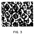
- the surface of tne ceramic or metallic carbide coating after laser-engraving comprises a series of microcavities or cells formed by (a) vaporization of some of the material and (b) the melting, moving and recasting of additional material when the coating material is hit by the laser pulse. It is readily seen that each cell has a ridge of coating material surrounding it which was thrown up by the melting, moving and recasting of coating material caused by the laser pulse. Some of the ridges ove l lap others which provides a clue to the direction of movement of the laser pulses. It has been found that the recast material differs considerably from the original coating.
- alumina-titania mixtures which as coated appear in separate phases but on recasting by laser treatment form a single phase material.
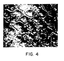
- major morphological changes are produced in the alumina coating material after the laser pulse hits it. This is best illustrated in Fig. 4 by the bright colored elongated particles along the ridges of coating material thrown up out of the microcavities or cells. It is believed that these bright particles are synthetic sapphire nodules formed by the action of the laser on the alumina coating material.
- the laser-engraved, ceramic-, or metallic carbide- coated friction rolls of this invention find application in the textile and steel industries for moving and performing work on strands, i.e., thread, yarn, filament, or wire and webs or other elongate materials, e.g., thin sheet steel, woven, knitted or bonded non-woven fabrics, ingots, slabs and the like. They can be used in the tape recording industry, the plastics sheet processing industry, photo-film processing industry, the photocopying industry, e.g., xerographic copy machines, newspaper handling machines and esssentially any machines used in the strand or web or elongate material handling industries.
- the novel friction rolls can be in the form of crimper roll pairs that form a nip through which the strand or web passes or in the form of a single capstan roll or draw roll where the web passes one-half or one-fourth the way around the roll or the strand passes around the roll one-half or more times, e.g., 1, 2 or 3 times.
- the novel friction rolls can include draw pins or guide pins which do not rotate but work on the elongate material, e.g., yarn or tow, by moving the elongate material in frictional contact with the draw pin or guide pin.
- the frictional and surface characteristics of the novel friction rolls are well suited for drawing, crimping and any other operation which requires a quick grasp ot the strand or web by the roll working surface and also a quick release at the appropriate time without snagging or tearing.
- the novel laser-patterned, ceramic-, or metallic carbide-, coated surfaces provide the quick grab-quick release capability and also are wear-resistant and capable of retaining the long-lasting and consistent frictional coefficients and surface characteristics.
- the Screen Size and Pattern designation for each coating as identified in the Examples uses S to designate a square pattern in which the depressions are in axial rows, i.e., rows parallel to the axis of the roll or cylinder, and in circumferential rows, i.e., rows extending around the circumference of the cylinder or roll forming a circle having its center lying on said axis, and wherein the center of each depression in an axial row is in the same circumferential row as a depression center in each of the two rows adjacent to it.
- each axial row is offset from each adjacent axial row to the extent that depression centers in one row are offset at an angle of 30 degrees (relative to an axial row or axial line) from adjacent depression centers in each axial ruw adjacent to it.
- each axial row is offset from each adjacent axial row to the extent that depression centers in one row are offset at an angle of 45 degrees (relative to an axial row or line) from adjacent depression centers in each axial row adjacent to it.
- the two or three digit number in the middle of the Screen Size and Pattern designations indicates the number of depressions per lineal inch measured in the direction of the first designation, i.e., for square patterns S, the middle two or three digit number gives the number of depressions or cells per lineal inch in the axial row which is the same as the number of cells in a circumferential row.
- the middle two or three digit number designates the number of depressions or cells per lineal inch in the 45 degree diagonal direction and for the 301 patterns, the miadle two or three digit number designates the number of depressions or cells per lineal inch in the 30 degree diagonal direction.
- the two or three digit number on the right hand end of the designations indicates the nominal depth in microns of each depression as measured from the bottcm of each depression to the top of the ridge surrounding it.
- a pair of cylindrical solid steel crimper rolls each having a diameter of 6", a width of 3" and a axial bore having a nominal diameter of 1.75" and a keyway for receiving a drive shaft and key, was degreased and otherwise prepared for coating with metallic carbide.
- a metallic carbide coating comprising 88.5 wt. % tungsten carbide, 8.5 wt. % cooalt and 3 wt. % chromium was applied to the outer cylindrical working surface of each roll.
- An epoxy sealant epoxy UC AR 100, was applied to the coatings.
- the purpose of the sealant was to close the pores in the coating to protect the steel of the roll from corrosion.
- the sealed coating was ground using a grinding wheel to a roughness of 15 to 25 R.
- the cylindrical surfaces were scratched with a coarse belt sanding machine to a roughness of 50 to 70 R a thereby producing conventional friction rolls.
- the coated cylindrical surfaces were abrasive sanded to a 20 to 25 R thereby leaving 4 mil thick coatings.
- the initial grinding step and the scratching step after detonation coating are superfluous and preferably are omitted.
- this example also illustrates that a conventional roll can be reground and subsequently treated to produce the novel rolls according to this invention.
- the coated cylindrical working surfaces were laser-engraved to produce a 45 degree offset pattern of depressions having a nominal screen of 400, (one roll surface had 392 depressions per inch and the other 386, along the 45 degree diagonal relative to the axial direction on the exterior cylinder surface).
- An unengraved band approximately 1/8" wide was retained along each circumferential edge of each roll in order to avoid the possible formation of burrs which could cause abrasion of the cheek plates conventionally used adjacent crimper rolls.
- the average nominal depth of the depressicns was 25 microns.
- Each depression was made by using 0.023 joule laser pulses each having a 64 microsecond duration. The pulse centers were separated by 500 microseconds.
- the resulting laser-engraved rolls were subjected to wet brush finishing using a stocky, bristley brush having a 12" diameter and nylon bristles each having a diameter of about 0.005".
- the brush was mounted so that the bristle tips engaged the laser-engraved surface of the roll and was rotated at 1756 rpm while the laser-engraved roll was rotated at 40 rpm.
- an aqueous abrasive slurry was applied to the laser-engraved roll at the nip of its contact with the bristley brush. Both the brush and the roll were rotated in the same rotational direction, i.e., both clockwise or both counterclockwise.
- the resulting pair of rolls was used as a crimper roll set to crimp nylon filaments of 22 denier in a tow band across the 3" faces of the rolls.
- This type ot tow is considered to be one of the more difficult L ypes to crimp. Also, this type of tow is considered to be aggressive to the crimper roll tending to cause hign wear.
- the tow was in a cohesive bundle in which the nylon filaments appeared to have a good crimp. A significant production run of tow was crimped by the novel crimper rolls and substantially no wear was observed on the rolls.
- Example 2 An additional set of two rolls identical to the set described in Example 1 was prepared for coating, coated with a metallic carbide coating and processed in the same manner as the rolls described in Example 1 except that, instead of a 451 diagonal pattern, the laser-engraved depressions were in a square pattern having a nominal screen of 400, i.e., about 396 depressions per inch in each circumferential row on the cylindrical surface and 403 depressions per inch in each axial row on the surface. Each depression had a nominal depth of 25 microns.
- the laser-engraved, coated rolls were used to crimp both 5 and 15 denier polyester fiber intended for use as a thermal insulating filament material. The rolls performed successfully in crisping the polyester fibers.
- Rolls #5 and #6 were each coated with LW-19 coating which is the same metallic carbide coating as identified in Example 1, i.e., 88.5 wt. % tungsten carbide, 8.5 wt. cobalt and 3 wt. t chromium.
- Each of these rolls were laser-engraved with 3 or 4 bands of screen patterns as identified in Table 1.
- R a designates roughness measurements. Each roughness number represents the mean of five readings taken around each band. All readings were taken at an angle of about 10 degrees to the roll axis. Also, in Table 1, C /F designates coefficient of friction of the bands which was measured. Several readings were made in both directions of rotation and showed very little difference in the coefficient of friction readings obtained. As can be seen in Table 1, roughness readings and coefficient of friction readings were made on each coating before brushing and after brushing with the nylon bristle brush and aqueous abrasive slurry as described in Example 1. The results shown in Table 1 illustrate the consistency of the coefficient of friction from coating to coating of the same kind as well as from coating to coating of the different types shown in Table 1.
- the lowest coefficient of friction after brushing was shown by coating *2 on roll #3, namely, 0.22
- the highest coefficient of friction after brushing was shown by the coating #1 on roll #1, namely, 0.265.
- the variance in coefficient of friction after brushing from the lowest to the hignest was very small illustrating the consistency in the coefficient from coating to coating and even in coatings of different types and patterns.
- Each of rolls #1, 4, 7 and 10 were coated by the method designated in Table 2, sealed with an epoxy coating, i.e., epoxy UCAR 100, which was applied witn a brush. The coating was then laser-engraved to provide the screen sizes and patterns set forth in Table 2 for each of Bands #1, 2 and 3 on each of these rolls.
- epoxy UCAR 100 epoxy UCAR 100
- Each of rolls #2, 5, 8 and 11 were coated by the method designated in Table 2 followed by sealing by brushing on an epoxy sealant followed by sanding witn a belt sander, followed by laser-engraving to produce the screen sizes and patterns designated in Table 2 for Bands 11, 2 and 3 of these rolls.
- Each of rolls #3, 6, 9 and 12 were made with coatings designated in Table 2 using the method designated therein. Thereafter, an epoxy sealant was applied to the coating. After the coating cooled it was ground with a grinding wheel and laser-engraved in three separated bands to produce the screen sizes and patterns designated in Table 2 for Bands 11, 2 and 3 of these rolls.
Landscapes
- Engineering & Computer Science (AREA)
- Mechanical Engineering (AREA)
- Chemical & Material Sciences (AREA)
- Physics & Mathematics (AREA)
- Optics & Photonics (AREA)
- Materials Engineering (AREA)
- Plasma & Fusion (AREA)
- Chemical Kinetics & Catalysis (AREA)
- Textile Engineering (AREA)
- Metallurgy (AREA)
- Organic Chemistry (AREA)
- Coating By Spraying Or Casting (AREA)
- Rolls And Other Rotary Bodies (AREA)
- Laser Beam Processing (AREA)
- Reduction Rolling/Reduction Stand/Operation Of Reduction Machine (AREA)
- Registering, Tensioning, Guiding Webs, And Rollers Therefor (AREA)
Applications Claiming Priority (4)
| Application Number | Priority Date | Filing Date | Title |
|---|---|---|---|
| US81133185A | 1985-12-20 | 1985-12-20 | |
| US811331 | 1985-12-20 | ||
| US811334 | 1985-12-20 | ||
| US06/811,334 US4794680A (en) | 1985-12-20 | 1985-12-20 | Novel wear-resistant laser-engraved ceramic or metallic carbide surfaces for friction rolls for working elongate members, method for producing same and method for working elongate members using the novel friction roll |
Publications (3)
| Publication Number | Publication Date |
|---|---|
| EP0230633A2 true EP0230633A2 (de) | 1987-08-05 |
| EP0230633A3 EP0230633A3 (en) | 1989-07-26 |
| EP0230633B1 EP0230633B1 (de) | 1992-08-12 |
Family
ID=27123457
Family Applications (1)
| Application Number | Title | Priority Date | Filing Date |
|---|---|---|---|
| EP86117788A Expired - Lifetime EP0230633B1 (de) | 1985-12-20 | 1986-12-19 | Reibungsrolle mit verschleissfester Oberfläche |
Country Status (8)
| Country | Link |
|---|---|
| EP (1) | EP0230633B1 (de) |
| JP (1) | JP2619631B2 (de) |
| KR (1) | KR910007925B1 (de) |
| CN (1) | CN1013143B (de) |
| AU (1) | AU605752B2 (de) |
| CA (1) | CA1287245C (de) |
| DE (1) | DE3686412T2 (de) |
| HK (1) | HK135593A (de) |
Cited By (15)
| Publication number | Priority date | Publication date | Assignee | Title |
|---|---|---|---|---|
| WO1990004058A1 (de) * | 1988-10-07 | 1990-04-19 | Iro Ab | Fadenspeicher- und -liefervorrichtung |
| EP0452880A1 (de) * | 1990-04-17 | 1991-10-23 | Canon Kabushiki Kaisha | Führungsteil und Gerät zu dessen Nutzung |
| WO1992007784A1 (en) * | 1990-11-05 | 1992-05-14 | Beloit Corporation | A winding device, use of a roller and corresponding roller |
| EP0483676A3 (en) * | 1990-11-02 | 1992-07-29 | Hoechst Aktiengesellschaft | Flat product with at least one regularly structured surface |
| EP0463333A3 (en) * | 1990-05-16 | 1992-08-05 | Hoechst Aktiengesellschaft | Thermoplastic film having a surface pattern and method for its fabrication |
| US5240198A (en) * | 1991-11-29 | 1993-08-31 | Beloit Technologies, Inc. | Compliant roller for a web winding machine |
| EP0599286A1 (de) * | 1992-11-25 | 1994-06-01 | Spinnstofffabrik Zehlendorf Ag | Fadenführendes Bauteil mit verbesserter Oberfläche und Verfahren zu seiner Herstellung |
| EP0631961A1 (de) * | 1993-06-19 | 1995-01-04 | Hoechst Aktiengesellschaft | Fadenführendes Bauteil mit verbesserter Oberfläche |
| FR2731378A1 (fr) * | 1995-03-10 | 1996-09-13 | Hoechst Ag | Procede de fabrication de pellicules etirees biaxialement et dispositif pour la mise en oeuvre du procede |
| EP1136574A1 (de) * | 2000-03-21 | 2001-09-26 | SM Schweizerische Munitionsunternehmung AG | Herstellung eines Prägwerkzeugs und dessen Anwendung |
| WO2007088990A1 (ja) | 2006-01-31 | 2007-08-09 | Canon Kabushiki Kaisha | 電子写真感光体の製造方法 |
| ES2316276A1 (es) * | 2006-04-10 | 2009-04-01 | Maschinenfabrik Rieter Ag | Rodillo de alimentacion para procesar un hilo de alma para obtener un entramado de fibras cortadas. |
| EP1711642B1 (de) * | 2004-01-28 | 2010-07-07 | Ford Global Technologies, LLC, A subsidary of Ford Motor Company | Durch thermisches spritzen aufgebrachte eisenhaltige schicht einer gleitfläche, insbesondere für zylinderlaufflächen von motorblöcken |
| CN114920040A (zh) * | 2022-05-16 | 2022-08-19 | 中山市创怡兴实业有限公司 | 搬送辊及其制备方法和喷墨打印机 |
| CN116892073A (zh) * | 2023-07-17 | 2023-10-17 | 无锡金通高纤股份有限公司 | 一种卷曲化纤长丝的装置及其控制方法 |
Families Citing this family (23)
| Publication number | Priority date | Publication date | Assignee | Title |
|---|---|---|---|---|
| JPH07109162B2 (ja) * | 1988-07-07 | 1995-11-22 | ユニオン・カーバイド・コーポレーション | 回転式ラビリンスシール部材用耐摩耗性、研削性レーザ彫刻セラミック乃至金属炭化物表面 |
| JPH0794298B2 (ja) * | 1988-08-19 | 1995-10-11 | 加藤発条株式会社 | 紙送り用ロールの製造方法 |
| US4974680A (en) * | 1988-11-14 | 1990-12-04 | Tokyo Electric Co., Ltd. | Sheet-feeding mechanism |
| JPH0757904B2 (ja) * | 1989-01-23 | 1995-06-21 | 住友金属工業株式会社 | 熱処理炉用ロールおよびその製造法 |
| JP4693288B2 (ja) * | 2001-06-26 | 2011-06-01 | 京セラ株式会社 | 光ファイバ用フェルール及びその製造方法 |
| EP1404910B2 (de) * | 2001-07-03 | 2011-06-15 | Oerlikon Textile GmbH & Co. KG | Vorrichtung zum stauchkräuseln |
| JP3828410B2 (ja) * | 2001-11-30 | 2006-10-04 | 住友ゴム工業株式会社 | 紙送りローラ及び紙送りローラの製造方法 |
| DE102009015557A1 (de) * | 2009-03-30 | 2010-10-07 | Oerlikon Textile Gmbh & Co. Kg | Vorrichtung zur Herstellung von Monofilen oder Bändchen |
| KR101050407B1 (ko) * | 2010-11-08 | 2011-07-19 | (주)맥스 | 뒤틀림방지 및 수명 연장 목재 데크 |
| CN102808123A (zh) * | 2011-06-02 | 2012-12-05 | 自贡硬质合金有限责任公司 | 破碎旧硬质合金的方法、设备以及设备的制备方法 |
| DE102012207398A1 (de) | 2012-05-04 | 2013-09-19 | Voith Patent Gmbh | Verfahren zum Herstellen einer Walze und Walze |
| CN102700342A (zh) * | 2012-05-24 | 2012-10-03 | 昆山市飞荣达电子材料有限公司 | 一种金属表面的图案形成方法 |
| CN104651989A (zh) * | 2015-01-28 | 2015-05-27 | 南通新源特种纤维有限公司 | 纺纱辊 |
| CN104726973B (zh) * | 2015-01-28 | 2017-07-25 | 南通新源特种纤维有限公司 | 摩擦纺纱机用筛网 |
| EP3461771B1 (de) * | 2016-06-28 | 2020-09-09 | Kyocera Corporation | Faserführung |
| EP3604635A4 (de) * | 2017-03-29 | 2020-12-30 | KYOCERA Corporation | Faserführung |
| CN107364185B (zh) * | 2017-07-27 | 2020-04-14 | 广州通泽机械有限公司 | 一种制袋机主牵引装置 |
| CN108796437A (zh) * | 2018-07-06 | 2018-11-13 | 苏州工业职业技术学院 | 一种提高零部件表面减摩耐磨性能的薄膜制备方法 |
| CN110217646A (zh) * | 2019-05-24 | 2019-09-10 | 湖北三江航天江北机械工程有限公司 | 降低碳纤维缠绕过程磨损量的方法 |
| CN111170043A (zh) * | 2020-01-17 | 2020-05-19 | 温州科旺机械有限公司 | 弹簧输送辊、组合输送辊、凹槽辊及输送组件 |
| JP7703215B2 (ja) * | 2021-08-24 | 2025-07-07 | 湯浅糸道工業株式会社 | 繊維用ガイド及びその製造方法 |
| CN114309955B (zh) * | 2022-01-13 | 2023-03-14 | 江苏富乐华半导体科技股份有限公司 | 一种陶瓷覆铜基板及其激光加工工艺 |
| CN120026274A (zh) * | 2025-04-21 | 2025-05-23 | 中机凯博表面技术江苏有限公司 | 一种具有自润滑涂层的活塞杆及其制备方法 |
Family Cites Families (8)
| Publication number | Priority date | Publication date | Assignee | Title |
|---|---|---|---|---|
| GB877291A (en) * | 1958-03-12 | 1961-09-13 | United Insulator Company Ltd | Improvements in thread guides |
| NL270846A (de) * | 1960-12-07 | |||
| JPS5192340A (de) * | 1975-02-10 | 1976-08-13 | ||
| LU80792A1 (fr) * | 1979-01-15 | 1980-08-08 | Ntre De Rech Metallurg Ct Voor | Dispsitif et procede pour effectuer des perforations a la surface des cylindres de laminoirs |
| GB2049102A (en) * | 1979-05-03 | 1980-12-17 | Csi Corp | Transfer roll |
| US4519840A (en) * | 1983-10-28 | 1985-05-28 | Union Carbide Corporation | High strength, wear and corrosion resistant coatings |
| EP0184568B1 (de) * | 1984-11-14 | 1989-11-02 | CENTRE DE RECHERCHES METALLURGIQUES CENTRUM VOOR RESEARCH IN DE METALLURGIE Association sans but lucratif | Verfahren zur Markierung der Oberfläche einer Walze |
| DE3512176A1 (de) * | 1985-04-03 | 1986-10-09 | Winfried 7758 Meersburg Heinzel | Verfahren zur oberflaechenbehandlung eines druckmaschinenzylinders |
-
1986
- 1986-12-05 CA CA000524641A patent/CA1287245C/en not_active Expired - Lifetime
- 1986-12-19 AU AU66766/86A patent/AU605752B2/en not_active Ceased
- 1986-12-19 DE DE8686117788T patent/DE3686412T2/de not_active Expired - Lifetime
- 1986-12-19 KR KR1019860011084A patent/KR910007925B1/ko not_active Expired
- 1986-12-19 JP JP61301924A patent/JP2619631B2/ja not_active Expired - Fee Related
- 1986-12-19 CN CN86108779A patent/CN1013143B/zh not_active Expired
- 1986-12-19 EP EP86117788A patent/EP0230633B1/de not_active Expired - Lifetime
-
1993
- 1993-12-09 HK HK1355/93A patent/HK135593A/xx unknown
Cited By (23)
| Publication number | Priority date | Publication date | Assignee | Title |
|---|---|---|---|---|
| US5160097A (en) * | 1988-10-07 | 1992-11-03 | Iro Ab | Yarn storage and feed device |
| WO1990004058A1 (de) * | 1988-10-07 | 1990-04-19 | Iro Ab | Fadenspeicher- und -liefervorrichtung |
| US5404154A (en) * | 1990-04-17 | 1995-04-04 | Canon Kabushiki Kaisha | Sheet feeding member having a film containing inorganic power |
| EP0452880A1 (de) * | 1990-04-17 | 1991-10-23 | Canon Kabushiki Kaisha | Führungsteil und Gerät zu dessen Nutzung |
| US5283116A (en) * | 1990-04-17 | 1994-02-01 | Canon Kabushiki Kaisha | Sheet feeding member having a film containing inorganic powder |
| EP0463333A3 (en) * | 1990-05-16 | 1992-08-05 | Hoechst Aktiengesellschaft | Thermoplastic film having a surface pattern and method for its fabrication |
| EP0483676A3 (en) * | 1990-11-02 | 1992-07-29 | Hoechst Aktiengesellschaft | Flat product with at least one regularly structured surface |
| US5215804A (en) * | 1990-11-02 | 1993-06-01 | Hoechst Aktiengesellschaft | Planar substrate with a regularly textured surface on at least one side |
| WO1992007784A1 (en) * | 1990-11-05 | 1992-05-14 | Beloit Corporation | A winding device, use of a roller and corresponding roller |
| US5240198A (en) * | 1991-11-29 | 1993-08-31 | Beloit Technologies, Inc. | Compliant roller for a web winding machine |
| EP0599286A1 (de) * | 1992-11-25 | 1994-06-01 | Spinnstofffabrik Zehlendorf Ag | Fadenführendes Bauteil mit verbesserter Oberfläche und Verfahren zu seiner Herstellung |
| EP0631961A1 (de) * | 1993-06-19 | 1995-01-04 | Hoechst Aktiengesellschaft | Fadenführendes Bauteil mit verbesserter Oberfläche |
| US5528799A (en) * | 1993-06-19 | 1996-06-25 | Hoechst Aktiengesellschaft | Thread-guiding component with improved surface |
| FR2731378A1 (fr) * | 1995-03-10 | 1996-09-13 | Hoechst Ag | Procede de fabrication de pellicules etirees biaxialement et dispositif pour la mise en oeuvre du procede |
| EP1136574A1 (de) * | 2000-03-21 | 2001-09-26 | SM Schweizerische Munitionsunternehmung AG | Herstellung eines Prägwerkzeugs und dessen Anwendung |
| WO2001071048A1 (de) * | 2000-03-21 | 2001-09-27 | Sm Schweizerische Munitionsunternehmung Ag | Herstellung eines prägewerkzeugs und dessen anwendung |
| EP1711642B1 (de) * | 2004-01-28 | 2010-07-07 | Ford Global Technologies, LLC, A subsidary of Ford Motor Company | Durch thermisches spritzen aufgebrachte eisenhaltige schicht einer gleitfläche, insbesondere für zylinderlaufflächen von motorblöcken |
| WO2007088990A1 (ja) | 2006-01-31 | 2007-08-09 | Canon Kabushiki Kaisha | 電子写真感光体の製造方法 |
| EP1983372A4 (de) * | 2006-01-31 | 2011-05-04 | Canon Kk | Verfahren zur herstellung eines elektrofotografischen fotoempfindlichen körpers |
| ES2316276A1 (es) * | 2006-04-10 | 2009-04-01 | Maschinenfabrik Rieter Ag | Rodillo de alimentacion para procesar un hilo de alma para obtener un entramado de fibras cortadas. |
| ES2316276B1 (es) * | 2006-04-10 | 2010-02-09 | Maschinenfabrik Rieter Ag | Rodillo de alimentacion para procesar un hilo de alma para obtener un entramado de fibras cortadas. |
| CN114920040A (zh) * | 2022-05-16 | 2022-08-19 | 中山市创怡兴实业有限公司 | 搬送辊及其制备方法和喷墨打印机 |
| CN116892073A (zh) * | 2023-07-17 | 2023-10-17 | 无锡金通高纤股份有限公司 | 一种卷曲化纤长丝的装置及其控制方法 |
Also Published As
| Publication number | Publication date |
|---|---|
| JPS62252689A (ja) | 1987-11-04 |
| CA1287245C (en) | 1991-08-06 |
| KR870006270A (ko) | 1987-07-10 |
| JP2619631B2 (ja) | 1997-06-11 |
| AU6676686A (en) | 1987-06-25 |
| CN86108779A (zh) | 1987-07-22 |
| AU605752B2 (en) | 1991-01-24 |
| CN1013143B (zh) | 1991-07-10 |
| DE3686412T2 (de) | 1992-12-24 |
| EP0230633A3 (en) | 1989-07-26 |
| EP0230633B1 (de) | 1992-08-12 |
| DE3686412D1 (de) | 1992-09-17 |
| KR910007925B1 (ko) | 1991-10-04 |
| HK135593A (en) | 1993-12-17 |
Similar Documents
| Publication | Publication Date | Title |
|---|---|---|
| US4794680A (en) | Novel wear-resistant laser-engraved ceramic or metallic carbide surfaces for friction rolls for working elongate members, method for producing same and method for working elongate members using the novel friction roll | |
| EP0230633B1 (de) | Reibungsrolle mit verschleissfester Oberfläche | |
| US5468568A (en) | Printing roller with a sleeve of thermally wound fiber-reinforced thermoplastics and a plasma-sprayed coating of copper or copper alloy | |
| US4566938A (en) | Transfer roll with ceramic-fluorocarbon coating containing cylindrical ink holes with round, beveled entrances | |
| IT8323269A1 (it) | Procedimento e apparecchiatura per applicare un rivestimento resistente all'usura su un materiale portante sagomato a striscia metallico sottile | |
| US6240639B1 (en) | Fluid metering roll and method of making the same | |
| GB2128551A (en) | Scraper with wear-resistant coating | |
| JPH0811877B2 (ja) | 連続紙ウェブに被覆剤を調節塗布しかつ均すためのドクターブレード | |
| US6339883B1 (en) | Method of making a roll for paper-making machine | |
| US20230083379A1 (en) | Method of applying a wear-resistant coating on a yankee drying cylinder, such coatings and yankee cylinders with such coatings | |
| JPH09122581A (ja) | 薄帯状金属キャリヤー上に耐摩耗コーティングを塗布する方法 | |
| JP3553877B2 (ja) | 紙工業用の被覆ロッド | |
| GB2295400A (en) | Blade and manufacture thereof using high velocity flame spraying | |
| US5364331A (en) | Heat resistant roll for use in steel plate manufacturing equipment | |
| JP3669719B2 (ja) | 伸線機用キャプスタンコーン | |
| JPH071021A (ja) | 圧延機のブライドルロール装置 | |
| JPH01317605A (ja) | ロール表面の加工方法 | |
| KR100717530B1 (ko) | 내마모성 물질로 코팅된 종이 코팅액 스크레이핑 작업용메탈 바 | |
| JP2987194B2 (ja) | 耐摩耗性チルド鋳鉄 | |
| JPH09300008A (ja) | 鋼板の調質圧延用ロール | |
| JP4307196B2 (ja) | 合成繊維製造用延伸ローラ及びその製造方法並びにそれを用いた合成繊維の製造方法 | |
| WO2023025439A1 (en) | A method of applying a wear-resistant coating on a yankee drying cylinder | |
| JPH0655124A (ja) | コーターブレード及びその製造方法 | |
| GB2091612A (en) | Mill roll | |
| JP2817862B2 (ja) | ドライヤーカンバスの走行ガイド用パーム |
Legal Events
| Date | Code | Title | Description |
|---|---|---|---|
| PUAI | Public reference made under article 153(3) epc to a published international application that has entered the european phase |
Free format text: ORIGINAL CODE: 0009012 |
|
| AK | Designated contracting states |
Kind code of ref document: A2 Designated state(s): AT BE CH DE FR GB IT LI LU NL SE |
|
| PUAL | Search report despatched |
Free format text: ORIGINAL CODE: 0009013 |
|
| AK | Designated contracting states |
Kind code of ref document: A3 Designated state(s): AT BE CH DE FR GB IT LI LU NL SE |
|
| 17P | Request for examination filed |
Effective date: 19890825 |
|
| 17Q | First examination report despatched |
Effective date: 19910321 |
|
| ITTA | It: last paid annual fee | ||
| RBV | Designated contracting states (corrected) |
Designated state(s): CH DE FR GB IT LI |
|
| GRAA | (expected) grant |
Free format text: ORIGINAL CODE: 0009210 |
|
| ITF | It: translation for a ep patent filed | ||
| AK | Designated contracting states |
Kind code of ref document: B1 Designated state(s): CH DE FR GB IT LI |
|
| REF | Corresponds to: |
Ref document number: 3686412 Country of ref document: DE Date of ref document: 19920917 |
|
| ET | Fr: translation filed | ||
| PGFP | Annual fee paid to national office [announced via postgrant information from national office to epo] |
Ref country code: GB Payment date: 19921113 Year of fee payment: 7 |
|
| PGFP | Annual fee paid to national office [announced via postgrant information from national office to epo] |
Ref country code: FR Payment date: 19921208 Year of fee payment: 7 |
|
| PGFP | Annual fee paid to national office [announced via postgrant information from national office to epo] |
Ref country code: CH Payment date: 19921210 Year of fee payment: 7 |
|
| PGFP | Annual fee paid to national office [announced via postgrant information from national office to epo] |
Ref country code: DE Payment date: 19921229 Year of fee payment: 7 |
|
| PLBE | No opposition filed within time limit |
Free format text: ORIGINAL CODE: 0009261 |
|
| 26N | No opposition filed | ||
| REG | Reference to a national code |
Ref country code: GB Ref legal event code: 732E |
|
| PG25 | Lapsed in a contracting state [announced via postgrant information from national office to epo] |
Ref country code: GB Effective date: 19931219 |
|
| PG25 | Lapsed in a contracting state [announced via postgrant information from national office to epo] |
Ref country code: LI Effective date: 19931231 Ref country code: CH Effective date: 19931231 |
|
| GBPC | Gb: european patent ceased through non-payment of renewal fee |
Effective date: 19931219 |
|
| PG25 | Lapsed in a contracting state [announced via postgrant information from national office to epo] |
Ref country code: FR Effective date: 19940831 |
|
| REG | Reference to a national code |
Ref country code: CH Ref legal event code: PL |
|
| PG25 | Lapsed in a contracting state [announced via postgrant information from national office to epo] |
Ref country code: DE Effective date: 19940901 |
|
| REG | Reference to a national code |
Ref country code: FR Ref legal event code: ST |
|
| PG25 | Lapsed in a contracting state [announced via postgrant information from national office to epo] |
Ref country code: IT Free format text: LAPSE BECAUSE OF NON-PAYMENT OF DUE FEES;WARNING: LAPSES OF ITALIAN PATENTS WITH EFFECTIVE DATE BEFORE 2007 MAY HAVE OCCURRED AT ANY TIME BEFORE 2007. THE CORRECT EFFECTIVE DATE MAY BE DIFFERENT FROM THE ONE RECORDED. Effective date: 20051219 |