EP0226976B1 - Verfahren zum Steuern des Druckverhältnisses einer Strahlpumpe - Google Patents
Verfahren zum Steuern des Druckverhältnisses einer Strahlpumpe Download PDFInfo
- Publication number
- EP0226976B1 EP0226976B1 EP86117325A EP86117325A EP0226976B1 EP 0226976 B1 EP0226976 B1 EP 0226976B1 EP 86117325 A EP86117325 A EP 86117325A EP 86117325 A EP86117325 A EP 86117325A EP 0226976 B1 EP0226976 B1 EP 0226976B1
- Authority
- EP
- European Patent Office
- Prior art keywords
- pressure
- target value
- propellant
- value
- jet pump
- Prior art date
- Legal status (The legal status is an assumption and is not a legal conclusion. Google has not performed a legal analysis and makes no representation as to the accuracy of the status listed.)
- Expired
Links
- 238000000034 method Methods 0.000 title claims description 13
- 239000003380 propellant Substances 0.000 claims description 33
- 230000001105 regulatory effect Effects 0.000 claims description 5
- 239000007788 liquid Substances 0.000 description 7
- 239000007789 gas Substances 0.000 description 6
- 238000010586 diagram Methods 0.000 description 5
- 230000001276 controlling effect Effects 0.000 description 3
- 238000005292 vacuum distillation Methods 0.000 description 3
- XLYOFNOQVPJJNP-UHFFFAOYSA-N water Substances O XLYOFNOQVPJJNP-UHFFFAOYSA-N 0.000 description 3
- 239000004604 Blowing Agent Substances 0.000 description 2
- 230000001419 dependent effect Effects 0.000 description 2
- 238000003825 pressing Methods 0.000 description 2
- 238000013019 agitation Methods 0.000 description 1
- 238000009835 boiling Methods 0.000 description 1
- 238000004364 calculation method Methods 0.000 description 1
- 230000003247 decreasing effect Effects 0.000 description 1
- 238000004821 distillation Methods 0.000 description 1
- 238000005265 energy consumption Methods 0.000 description 1
- 238000010438 heat treatment Methods 0.000 description 1
- 238000007654 immersion Methods 0.000 description 1
- 238000003754 machining Methods 0.000 description 1
- 238000004519 manufacturing process Methods 0.000 description 1
- 238000007738 vacuum evaporation Methods 0.000 description 1
Images

Classifications
-
- F—MECHANICAL ENGINEERING; LIGHTING; HEATING; WEAPONS; BLASTING
- F04—POSITIVE - DISPLACEMENT MACHINES FOR LIQUIDS; PUMPS FOR LIQUIDS OR ELASTIC FLUIDS
- F04F—PUMPING OF FLUID BY DIRECT CONTACT OF ANOTHER FLUID OR BY USING INERTIA OF FLUID TO BE PUMPED; SIPHONS
- F04F5/00—Jet pumps, i.e. devices in which flow is induced by pressure drop caused by velocity of another fluid flow
- F04F5/44—Component parts, details, or accessories not provided for in, or of interest apart from, groups F04F5/02 - F04F5/42
- F04F5/48—Control
- F04F5/52—Control of evacuating pumps
Definitions
- the invention relates to a method for controlling the pressure ratio of a jet pump for the purpose of regulating a predetermined operating vacuum.
- Jet pumps e.g. Propellant steam pump, gas jet pump or water jet pump
- the flow energy of a blowing agent through nozzles and diffusers is used for the purpose of sucking or pressing a medium to be conveyed.
- Gases, vapors and liquids can be used as propellants and conveyors.
- Jet pumps are easy to manufacture and have no moving parts, but they have a relatively low efficiency, which also changes when the operating conditions change, e.g. the pressures and flow rates is greatly reduced. Because of the difficulty of the generally meshed or multi-loop control of a jet pump, such devices are operated in practice with constant propellant pressure, the excess energy is destroyed by throttling, adding foreign gas or accepting a lower than the required vacuum or suction pressure.
- Jet pumps preferably steam jet pumps, are used, for example, as suction pressure generators in vacuum distillation.
- a prescribed behavior is to be achieved simultaneously for a number of controlled variables.
- these sizes are mutually dependent; furthermore, any regulatory intervention generally influences the other control variables to a greater or lesser extent; it is therefore not possible to use separate, but only meshed controllers.
- the problems of autonomy, invariance, controllability and observability associated with such multiple regulations make the use of conventional P, I, Pl, PID control methods and the like illusory, at least for economic reasons.
- the amount of propellant G 1 required is therefore only dependent on a function of Pe and Pa. Since this function is in the form of a pressure ratio, the term "controlling the pressure ratio" in the generic method means controlling Pe and / or Pa.
- the invention has for its object to provide a method by means of which the suction pressure generated in the conveying means can be kept constant within predetermined limits and times by changing the propellant pressure and thus the amount of propellant and in which the energy consumption can be kept optimally low.
- the solution according to the invention consists in that a setpoint value for the pressure ratio is determined from the continuously measured value of the operating vacuum by computer-aided iterative step-by-step change of an existing value of the pressure ratio.
- the actual value of the operating vacuum is measured, processed to an output variable by the computer-aided iterative change, and this is used as a manipulated variable for the propellant pressure, i.e. is used for the amount of propellant supplied to the jet pump per unit of time
- the propellant pressure can always be optimally adapted to the requirements on the vacuum side. In this way, energy savings of up to 50% can be achieved in a vacuum distillation or vacuum evaporation plant, for example, compared to conventional operation.
- the setpoint value for the pressure ratio determined by calculation can be supplied in the form of a control value for the propellant pressure to a control valve located in the line of the propellant or can be used as a reference variable for the propellant pressure and / or output pressure in assigned control loops.
- the iterative change is preferably effected by using an algorithm in conjunction with a computer. If necessary, the target value is determined by endlessly repeating the algorithm by the computer at its own speed. This means, when changing its input variable, namely the measured value of the suction pressure, to change the output variable, namely the manipulated variable for the propellant pressure, until the value of the input variable is again within the specified limits.
- the output variable of the computer is therefore not a value that has a fixed functional connection to the input variable, but results from the iterative increase or decrease of the previously available output variable.
- the rate of change of the setpoint should be adapted to the size and rate of change of the setpoint-actual value deviation of the operating vacuum within preselectable limits.
- Fig. 1 the quantity ratio G1 / G2 of the amount of propellant G1 and amount of funding G2 is plotted on the ordinate, and the pressure ratio f (p) is plotted on the abscissa.
- the latter is a function of the propellant pressure Pe, the pressure Pa at the outlet of the jet pump and the suction pressure Po.
- the pressure ratio of a jet pump operated with liquid is defined as follows:
- the relationship arises when the jet pump is operated with a gas for the pressure ratio In this ae is the adiabatic exponent of the gas.
- the corresponding enthalpy drops occur instead of the pressure drops (h, s diagram).
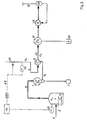
- the vacuum container 1 of a distillation column which can be equipped with a cooler 2, a distillate receiver 3, a liquid sump 4, a heater 5 and a liquid supply line 6, is connected to a steam jet pump 8 via a conveying line 7.
- the jet pump 8 the negative pressure is generated by pressing a propellant through a propellant line 9 through a propellant nozzle at high speed, with the result that the pressure at the nozzle outlet is greatly reduced and the conveying means present there is sucked in.
- gas in the container 1 is sucked off and a suction pressure Po is set in the container.
- the suction pressure must not exceed a certain maximum value because of the pressure dependence of the boiling temperature of the liquid 4 in the container 1.
- the actual value of the suction pressure Po generated in the container 1 is therefore measured with the aid of a vacuum measuring device 11 and fed to a computer denoted by 12 with an algorithm as an input variable.
- the input variable of the suction pressure Pn is processed by the algorithm into an output variable, which in turn serves as a setpoint or manipulated variable for the propellant pressure Pe of the jet pump 8.
- the manipulated variable is switched via a direct line 13 to a control or regulating valve 14 located in the propellant line 9.
- the setpoint of the propellant pressure determined in the computer 12 can also be fed to an intermediate propellant pressure regulator 15.
- the active lines of the pressure regulator 15 which may be necessary for this purpose are shown in dashed lines in the drawing. The direction of information is indicated by arrows.
- the outlet 16 of the jet pump leads, when operated with steam, into corresponding condensate systems, which may be pre-evacuated.
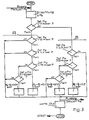
- 3 shows an exemplary embodiment of a flow diagram of the algorithm to be used in the computer 12. In this case, specific numerical values are given for all parameters to make them easier to understand. However, these values are only to be regarded as an example.
- Po mean the suction pressure detected by the measuring device 11 in the container 1, Pe the propellant pressure supplied via the propellant line 9 of the jet pump 8 and A Po the difference to the previous measured value of the vacuum Po.
- the respective measured value of the suction pressure Po generated that is to say the input variable determined by the vacuum measuring device 11, is given to the computer 12.
- the algorithm shown as an example has two main processing branches A and B, which are to be selected depending on the size of the rate of change and the setpoint / actual value deviation of the computer input variable.
- branches A, B By selecting and designing branches A, B, it is possible to adapt the rate of change of the output variable to that of the input variable within preselectable limits.
- the output variable Pe of the computer 12 results from iteratively increasing or decreasing the output variable Pe present in each case and additionally takes into account the dead time of the system caused by the system by means of a predetermined waiting time.
Landscapes
- Engineering & Computer Science (AREA)
- Physics & Mathematics (AREA)
- Fluid Mechanics (AREA)
- Mechanical Engineering (AREA)
- General Engineering & Computer Science (AREA)
- Jet Pumps And Other Pumps (AREA)
- Vaporization, Distillation, Condensation, Sublimation, And Cold Traps (AREA)
- Control Of Fluid Pressure (AREA)
- Feedback Control In General (AREA)
- Control Of Non-Positive-Displacement Pumps (AREA)
Description
- Die Erfindung betrifft ein Verfahren zum Steuern des Druckverhältnisses einer Strahlpumpe zwecks Regelung eines vorgegebenen Betriebsvakuums.
- In einer Strahlpumpe, z.B. Treibdampfpumpe, Gasstrahlpumpe oder Wasserstrahlpumpe, wird die Strömungsenergie eines Treibmittels durch Düsen und Diffusoren zum Zwecke des Saugens bzw. Drückens eines zu fördernden Mittels ausgenutzt. Als Treib- und Fördermittel kommen Gase, Dämpfe und Flüssigkeiten in Frage. Strahlpumpen sind einfach herzustellen und besitzen keine bewegten Teile, sie haben jedoch einen relativ geringen Wirkungsgrad, der zudem bei Änderung der Betriebsbedingungen, z.B. der Drücke und Fördermengen, stark vermindert wird. Wegen der Schwierigkeit der in der Regel vermaschten bzw. mehrschweifigen Regelung einer Strahlpumpe werden solche Apparate in der Praxis mit konstantem Treibmitteldruck betrieben, die überschüssige Energie wird durch Drosselung, Fremdgaszugabe oder Inkaufnahme eines niedrigeren als des benötigten Unterdrucks bzw. Saugdrucks vernichtet.
- Strahlpumpen, vorzugsweise Dampfstrahlpumpen, werden beispielsweise als Saugdruckerzeuger in der Vakuumdestillation eingesetzt. Bei derartig komplizierten Anlagen soll gleichzeitig für eine Reihe von Regelgrößen ein vorgeschriebenes Verhalten erreicht werden. Diese Größen sind jedoch wechselseitig abhängig; ferner beeinflußt jeder regulierende Eingriff die anderen Regel größen im allgemeinen sogar mehr oder weniger stark; es können daher nicht getrennte sondern nur vermaschte Regler eingesetzt werden. Die mit solchen Mehrfachregelungen verbundene Problematik der Autonomie, Invarianz, Steuerbarkeit und Beobachtbarkeit macht den Einsatz herkömmlicher P-, I-, Pl-, PID-Regelungsverfahren und dergleichen zumindest aus wirtschaftlichen Gründen illusorisch.
- Das Mengenverhältnis G1/G2 von Treibmittelmenge G1 zu Fördermittelmenge G2 ist bei einer Strahlpumpe mit gegebenen Abmaßen eine Funktion von
- Pe = Treibmitteldruck;
- Pa = Druck am Austritt der Strahlpumpe; und
- Po = Saugdruck.
- Bei vorgegebenem Saugdruck Po und vorgegebener Fördermittelmenge G2 ist die erforderliche Treibmittelmenge G 1 daher nur noch abhängig von einer Funktion von Pe und Pa. Da diese Funktion die Form eines Druckverhältnisses besitzt, wird im gattungsgemäßen Verfahren unter dem Begriff "Steuern des Druckverhältnisses" das Steuern von Pe und/oder Pa verstanden.
- Der Erfindung liegt die Aufgabe zugrunde, ein Verfahren zu schaffen, mit dem der im Fördermittel erzeugt Saugdruck durch Veränderung des Treibmitteldrucks und damit der Treibmittelmenge innerhalb vorgegebener Grenzen und Zeiten konstant zu halten und in dem der Energieverbrauch optimal niedrig zu halten ist. Die erfindungsgemäße Lösung besteht darin, daß aus dem kontinuierlich gemessenen Wert des Betriebsvakuums durch rechnergestütztes iteratives schrittweises Ändern eines vorhandenen Wertes des Druckverhältnisses ein Sollwert für das Druckverhältnis ermittelt wird.
- Dadurch, daß erfindungsgemäß der Istwert des Betriebsvakuums gemessen, durch die rechnergestützte iterative Änderung zu einer Ausgangsgröße verarbeitet und diese als Stellgröße für den Treibmitteldruck, d.h. für die pro Zeiteinheit der Strahlpumpe zugeführte Treibmittelmenge, verwendet wird, läßt sich der Treibmitteldruck den Erfordernissen auf der Vakuumseite immer optimal anpassen. Auf diese Weise läßt sich beispielsweise in einer Vakuum-destillations- oder Vakuumeindampfanlage eine Energieeinsparung von bis zu 50% im .. Vergleich zu herkömmlicher Betriebsweise erzielen. Gemäß weiterer Erfindung kann der durch Berechnung ermittelte Sollwert für das Druckverhältnis in Form eines Stellwertes für den Treibmitteldruck einem in der Leitung des Treibmittels liegenden Regelventil zugeführt oder als Führungsgröße für den Treibmitteldruck und/oder Ausgangsdruck in zugeordneten Regelkreisen verwendet werden.
- Vorzugsweise wird die iterative Änderung durch die Anwendung eines Algorithmus in Verbindung mit einem Rechner bewirkt. Gegebenenfalls wird der Sollwert dadurch ermittelt, daß man den Algorithmus vom Rechner mit der ihm eigenen Geschwindigkeit endlos wiederholt. Das bedeutet, bei Änderungen seiner Eingangsgröße, nämlich des gemessenen Wertes des Saugdrucks, die Ausgangsgröße, nämlich die Stellgröße für den Treibmitteldruck, so lange zu verändern, bis sich der Wert der Eingangsgröße wieder innerhalb der vorgegebenen Grenzen befindet. Die Ausgangsgröße des Rechners ist daher kein Wert, der in einem festen funktionellen Zusammenhang zu der Eingangsgröße steht, sondern ergibt sich durch die iterative Erhöhung oder Erniedrigung der jeweils vorher vorhandenen Ausgangsgröße.
- Zusätzlich ist es günstig, wenn nach jeder schrittweisen Veränderung des Sollwertes eine der Totzeit des Systems entsprechende Wartezeit eingehalten wird. Schließlich soll die Änderungsgeschwindigkeit des Sollwertes an die Größe und Änderungsgeschwindigkeit der Soll-Istwertabweichung des Betriebsvakuums in vorwählbaren Grenzen angepaßt werden. Vorzugsweise wird dazu ein Algorithmus mit verschiedenen Bearbeitungszweigen für verschiedene Bereiche der Soll-Istwertabweichung des Betriebsvakuums und deren Ände-' rungsgeschwindigkeit verwendet. Auf diese Weise wird es möglich, die Änderungsgeschwindigkeit der Ausgangsgröße an diejenige der Eingangsgröße in vorwählbaren Grenzen anzupassen.
- Anhand der schematischen Zeichnung werden Einzelheiten der Erfindung erläutert. Es zeigen:
- Fig. 1 ein Diagramm betreffend die Abhängigkeit des Mengenverhältnisses von Treibmittelmenge und Fördermittelmenge vom Treibmitteldruck, Austrittsdruck und Saugdruck einer Strahlpumpe;
- Fig. 2 eine Vorrichtung zur Vakuumerzeugung bei einer Vakuumdestillation; und
- Fig. 3 ein Fließbild eines Algorithmus zum iterativen Bestimmen eines Stellwerts.
- In Fig. 1 werden in der Ordinate das Mengerverhältnis G1/G2 von Treibmittelmenge G1 und Fördermittelmenge G2 sowie in der Abszisse das Druckverhältnis f(p) auf getragen. Letzteres ist eine Funktion des Treibmitteldrucks Pe, des Drucks Pa am Austritt der Strahlpumpe und des Saugdrucks Po. Bei einer mit Flüssigkeit betriebenen Strahlpumpe ist das Druckverhältnis wie folgt definiert:


- In dem in Fig. 2 dargestellten Ausführungsbeispiel wird der Vakuumbehälter 1 einer Destillationskolonne, die mit einem Kühler 2, einer Destillatvorlage 3, einem Flüssigkeitssumpf 4, einer Heizung 5 und einer Flüssigkeitszufuhrleitung 6 ausgestattet sein kann, über eine Fördermittelzuleitung 7 mit einer Dampfstrahlpumpe 8 verbunden. In der Strahlpumpe 8 wird der Unterdruck dadurch erzeugt, daß man ein Treibmittel über eine Treibmitteleitung 9 mit großer Geschwindigkeit durch eine Treibdüse preßt mit dem Ergebnis, daß der Druck am Düsenausgang stark herabgesetzt und das dort anstehende Fördermittel angesaugt wird. Hierdurch wiederum wird in dem Behälter 1 befindliches Gas abgesaugt und im Behälter ein Saugdruck Po eingestellt. Der Saugdruck darf wegen der Druckabhängigkeit der Siedetemperatur der im Behälter 1 befindlichen Flüssigkeit 4 einen bestimmten Maximalwert nicht überschreiten. Es sollen oder können aber auch bestimmte Minimalwerte eingehalten werden. Der Istwert des im Behälter 1 erzeugten Saugdrucks Po wird daher mit Hilfe eines Vakuum-Meßgeräts 11 gemessen und einem mit 12 bezeichneten Rechner mit Algorithmus als Eingangsgröße zugeführt. In dem Rechner 12 wird die Eingangsgröße des Saugdrucks Pn durch den Algorithmus zu einer Ausgangsgröße verarbeitet, die wiederum als Sollwert oder Stellgröße für den Treibmitteldruck Pe der Strahlpumpe 8 dient.
- Im Ausführungsbeispiel wird die Stellgröße über eine direkte Leitung 13 auf ein in der Treibmittelleitung 9 liegendes Stell- bzw. Regelventil 14 geschaltet. Alternativ kann der im Rechner 12 ermittelte Sollwert des Treibmitteldrucks auch einem zwischengeschalteten Treibmitteldruckregler 15 zugeführt werden. Die gegebenenfalls dafür erforderlichen Wirkleitungen des Druckreglers 15 werden in der Zeichnung gestrichelt dargestellt. Die Informationsrichtung wird durch Pfeile angedeutet. Der Ausgang 16 der Strahlpumpe führt beim Betrieb mit Dampf in entsprechende Kondensatsysteme, die gegebenenfalls vorevakuiert sind. Fig. 3 zeigt ein Ausführungsbeispiel eines Fließbilds des in dem Rechner 12 zu verwendenden Algorithmus. Hierbei werden zur besseren Verständlichkeit für sämtliche Parameter konkrete Zahlenwerte angegeben. Diese Werte sind jedoch nur als Beispiel anzusehen. In der Zeichnung bedeuten Po den durch das Meßgerät 11 erfaßten Saugdruck im Behälter 1, Pe den über die Treibmittelleitung 9 der Strahlpumpe 8 zugeführten Treibmitteldruck und A Po die Differenz zum vorhergehenden Meßwert des Unterdrucks Po.
- Am Start des Algorithmus wird der jeweilige Meßwert des erzeugten Saugdrucks Po, also die vom Vakuummeßgerät 11 bestimmte Eingangsgröße auf den Rechner 12 gegeben. Der als Beispiel dargestellte Algorithmus besitzt zwei Hauptbearbeitungszweige A und B, die je nach Größe der Änderungsgeschwindigkeit und der Sollwert/Istwert-Abweichung der Rechner-Eingangsgröße auszuwählen sind. Durch Auswahl und Ausgestaltung der Zweige A, B ist es möglich, die Änderungsgeschwindigkeit der Ausgangsgröße in vorwählbaren Grenzen an diejenige der Eingangsgröße anzupassen. In beiden Fällen ergibt sich die Ausgangsgröße Pe des Rechners 12 durch iterative Erhöhung oder Erniedrigung der jeweils vorhandenen Ausgangsgröße Pe und berücksichtigt durch eine vorgegebene Wartezeit zusätzlich die durch die Anlage bedingte Totzeit des Systems.
- Nach Ermittlung der Ausgangsgröße des Rechners 12 wird der Algorithmus mit der ihm eigenen Geschwindigkeit endlos wiederholt. In Fig. 3 wird diese Endlosschleife durch das Start-Zeichen am Fuß des Fließbilds angedeutet.
-
- 1 = Behälter
- 2 = Kühler
- 3 = Destillatvorlage
- 4 = Flüssigkeitssumpf
- 5 = Heizung
- 6 - Flüssigkeitszuführleitung
- 7 = Fördermittelleitung
- 8 = Strahlpumpe
- 9 = Treibmittelleitung
- 11 = Vakuummeßgerät
- 12 = Rechner
- 13 = Stellgrößenleitung
- 14 = Regelventil
- 15 = Druckregler
- 16 = Ausgang Strahlpumpe
- 17 = Kondensator Treibdampf
- 18 = barometrisches Tauchgefäß Strahlpumpe 19 = Wasserringpumpe
- 20 = Wasserabscheider
- 21 = atmosphärischer Ausgang
- 22 = Druckmeßgerät
- Po = Saugdruck
- Pe = Treibmitteldruck
- Pa = Druck am Austritt der Strahlpumpe
- Pu = Unterdruck Destillierapparat
- G1 = Treibmittelmenge
- G2 = Fördermittelmenge
- f(p) = Druckverhältnis
- A,B = Hauptbearbeitungszweige
Claims (8)
Applications Claiming Priority (2)
| Application Number | Priority Date | Filing Date | Title |
|---|---|---|---|
| DE19853545612 DE3545612A1 (de) | 1985-12-21 | 1985-12-21 | Verfahren zum steuern des druckverhaeltnisses einer strahlpumpe |
| DE3545612 | 1985-12-21 |
Publications (2)
| Publication Number | Publication Date |
|---|---|
| EP0226976A1 EP0226976A1 (de) | 1987-07-01 |
| EP0226976B1 true EP0226976B1 (de) | 1989-06-07 |
Family
ID=6289274
Family Applications (1)
| Application Number | Title | Priority Date | Filing Date |
|---|---|---|---|
| EP86117325A Expired EP0226976B1 (de) | 1985-12-21 | 1986-12-12 | Verfahren zum Steuern des Druckverhältnisses einer Strahlpumpe |
Country Status (8)
| Country | Link |
|---|---|
| US (1) | US4762467A (de) |
| EP (1) | EP0226976B1 (de) |
| JP (1) | JPS62157299A (de) |
| BR (1) | BR8606320A (de) |
| DE (2) | DE3545612A1 (de) |
| GB (1) | GB2184868B (de) |
| MY (1) | MY100827A (de) |
| PH (1) | PH23382A (de) |
Families Citing this family (19)
| Publication number | Priority date | Publication date | Assignee | Title |
|---|---|---|---|---|
| US5186219A (en) * | 1984-11-08 | 1993-02-16 | Earth Resources Consultants, Inc. | Cylinder rupture vessel |
| EP0860609B1 (de) * | 1991-09-10 | 2005-11-30 | Smc Kabushiki Kaisha | Durch Flüssigkeitsdruck betätigte Vorrichtung |
| US5383499A (en) * | 1992-05-04 | 1995-01-24 | Earth Resources Corporation | System for removal of unknown, corrossive, or potentially hazardous gases from a gas container |
| US5474114A (en) | 1993-05-28 | 1995-12-12 | Earth Resources Corporation | Apparatus and method for controlled penetration of compressed fluid cylinders |
| US5624239A (en) * | 1994-12-14 | 1997-04-29 | Osika; Thomas W. | Portable pneumatic vacuum source apparatus and method |
| US5900216A (en) * | 1996-06-19 | 1999-05-04 | Earth Resources Corporation | Venturi reactor and scrubber with suckback prevention |
| US5879548A (en) * | 1997-05-07 | 1999-03-09 | Al-Ali; Amier | Method and apparatus for collecting a substance |
| US5868174A (en) * | 1997-07-28 | 1999-02-09 | Earth Resources Corporation | System for accessing and extracting contents from a container within a sealable recovery vessel |
| US6164344A (en) * | 1997-07-28 | 2000-12-26 | Earth Resources Corporation | Sealable recovery vessel system and method for accessing valved containers |
| US6083384A (en) * | 1999-02-02 | 2000-07-04 | Al-Ali; Amier | Method and apparatus for collecting a substance |
| US20030202874A1 (en) * | 2002-04-29 | 2003-10-30 | Marsbed Hablanian | Methods and apparatus for controlling power in vapor jet vacuum pumps |
| GB2399864A (en) * | 2003-03-22 | 2004-09-29 | Ellastar Ltd | A system and process for pumping multiphase fluids |
| US8826680B2 (en) * | 2005-12-28 | 2014-09-09 | Johnson Controls Technology Company | Pressure ratio unload logic for a compressor |
| FR2944218B1 (fr) * | 2009-04-09 | 2012-06-15 | Total Sa | Dipositif ejecteur pour former un melange sous pression de liquide et de gaz, et compresseur de gaz comprenant un tel dispositif ejecteur |
| US8543245B2 (en) * | 2009-11-20 | 2013-09-24 | Halliburton Energy Services, Inc. | Systems and methods for specifying an operational parameter for a pumping system |
| US9039385B2 (en) | 2011-11-28 | 2015-05-26 | Ford Global Technologies, Llc | Jet pump assembly |
| WO2013120802A1 (de) | 2012-02-13 | 2013-08-22 | J. Schmalz Gmbh | Verfahren zum betreiben eines unterdruckerzeugers und unterdruckerzeuger zur durchführung des verfahrens |
| GB201320202D0 (en) * | 2013-11-15 | 2014-01-01 | Caltec Ltd | A flowmeter |
| DE102014101915B4 (de) * | 2014-02-14 | 2024-08-01 | Avl Analytical Technologies Gmbh | Vorrichtung und Verfahren zur Bestimmung der Konzentration zumindest eines Gases in einem Probengasstrom mittels Infrarotabsorptionsspektroskopie |
Family Cites Families (10)
| Publication number | Priority date | Publication date | Assignee | Title |
|---|---|---|---|---|
| US2140306A (en) * | 1937-06-19 | 1938-12-13 | Albert E Beals | Control of gas or vapor compressors |
| BE586679A (fr) * | 1959-01-28 | 1970-07-18 | Siderurgie Fse Inst Rech | Procédé et dispositif pour le refroidissement et l'évacuation des gaz provenant de l'affinage pneumatiques des fontes. |
| US3456871A (en) * | 1967-07-18 | 1969-07-22 | Schutte & Koerting Co | Method and apparatus for controlling a jet pump |
| DE1703040A1 (de) * | 1968-03-25 | 1971-12-09 | Koerting Ag | Verfahren zur Steuerung einer Vakuumpumpen-Kombination und Einrichtung zur Durchfuehrung des Verfahrens |
| JPS5587900A (en) * | 1978-12-26 | 1980-07-03 | Tlv Co Ltd | Combined pump |
| US4332527A (en) * | 1979-08-10 | 1982-06-01 | Lear Siegler, Inc. | Variable speed centrifugal pump |
| JPS5779300A (en) * | 1980-11-05 | 1982-05-18 | Toyobo Co Ltd | Front pressure control method of ejector nozzle |
| JPS5835299A (ja) * | 1981-08-27 | 1983-03-01 | Aisin Seiki Co Ltd | 大型車用負圧供給システム |
| JPS6081500A (ja) * | 1983-10-11 | 1985-05-09 | Sakou Giken:Kk | 蒸気エゼクタ− |
| JPS6098200A (ja) * | 1983-11-04 | 1985-06-01 | Asahi Enterp:Kk | ベンチユリポンプ |
-
1985
- 1985-12-21 DE DE19853545612 patent/DE3545612A1/de not_active Withdrawn
-
1986
- 1986-12-01 GB GB8628677A patent/GB2184868B/en not_active Expired - Fee Related
- 1986-12-12 DE DE8686117325T patent/DE3663841D1/de not_active Expired
- 1986-12-12 EP EP86117325A patent/EP0226976B1/de not_active Expired
- 1986-12-19 PH PH34631A patent/PH23382A/en unknown
- 1986-12-19 BR BR8606320A patent/BR8606320A/pt not_active IP Right Cessation
- 1986-12-19 MY MYPI86000232A patent/MY100827A/en unknown
- 1986-12-19 US US06/944,630 patent/US4762467A/en not_active Expired - Fee Related
- 1986-12-22 JP JP61304051A patent/JPS62157299A/ja active Pending
Also Published As
| Publication number | Publication date |
|---|---|
| DE3663841D1 (en) | 1989-07-13 |
| DE3545612A1 (de) | 1987-06-25 |
| GB8628677D0 (en) | 1987-01-07 |
| MY100827A (en) | 1991-03-15 |
| BR8606320A (pt) | 1987-10-06 |
| US4762467A (en) | 1988-08-09 |
| EP0226976A1 (de) | 1987-07-01 |
| PH23382A (en) | 1989-07-26 |
| GB2184868A (en) | 1987-07-01 |
| GB2184868B (en) | 1990-03-28 |
| JPS62157299A (ja) | 1987-07-13 |
Similar Documents
| Publication | Publication Date | Title |
|---|---|---|
| EP0226976A1 (de) | Verfahren zum Steuern des Druckverhältnisses einer Strahlpumpe | |
| EP2060788B1 (de) | Verfahren zum Ansteuern einer Pumpenanordnung und Pumpenanordnung | |
| DE60015003T2 (de) | Druckregelvorrichtung für eine Vakuumkammer, und eine mit einer solchen Vorrichtung versehenen Vakuumpumpeinheit | |
| DE2756916C2 (de) | Vorrichtung zur Einrichtung der Fördermenge einer Wasserwerk-Pumpenanordnung | |
| EP0636420B1 (de) | Pulverfördervorrichtung, insbesondere für Beschichtungspulver | |
| DE69111762T2 (de) | Verfahren zur Regelung des Konditionierens eines Gases und Vorrichtung dazu. | |
| EP0261530A2 (de) | Verfahren und Vorrichtung zur Trennung der Bestandteile des einem Spender "in vivo" entnommenen Blutes | |
| DE4000165A1 (de) | Vorrichtung zur dampfsicherheitsrueckgewinnung, insbesondere fuer kraftstoffabfuellanlagen | |
| DE69610985T2 (de) | Verfahren zur rückgewinnung von dämpfen an einer flüssigkeits-zapfstelle | |
| DE3023550A1 (de) | Steuersystem zur steuerung der kraftstoffzufuhr bei einer gasturbine | |
| EP3655663B1 (de) | Verfahren zum regeln von wenigstens zwei ventilatoren | |
| DE19618728A1 (de) | Verfahren und Vorrichtung zur Turbulenzströmungs-Leitungsreinigung | |
| DE69509311T2 (de) | Vorhersagemethoden und unscharfe Logik verwendende Methode und Vorrichtung zur Regelung eines Parameters innerhalb eines zulässigen Bereichs | |
| DE102007046738A1 (de) | Pulversprühbeschichtungsverfahren und -vorrichtung | |
| DE2312228A1 (de) | Druckwasserreaktor | |
| DE3105355C2 (de) | ||
| DE2917651C2 (de) | ||
| EP0502303B1 (de) | Verfahren zur Behandlung von Gegenständen mit einem Fluor enthaltenden Gas sowie Vorrichtung zu seiner Durchführung | |
| CH663268A5 (de) | Heizanlage an einem fernheizsystem. | |
| DE2045782C3 (de) | Brennstoffregeleinrichtung für ein Gasturbinentriebwerk | |
| EP3330644A1 (de) | Kälteanlage und verfahren zur regelung einer kälteanlage | |
| DE4410405C1 (de) | Verfahren und Vorrichtung zum Trennen eines Gemisches aus Flüssigkeiten und Substanzen mit jeweils unterschiedlichen Siedetemperaturen | |
| DE346294C (de) | Regelungsverfahren fuer Vorrichtungen zum Eindampfen von Loesungen mittels verdichteter Abdaempfe | |
| DE404580C (de) | Verfahren und Vorrichtung zum Behandeln von Gasen mit Fluessigkeiten in Waschtuermen | |
| DE2914722C2 (de) | Anlage für die galvanotechnische Behandlung von Gegenständen |
Legal Events
| Date | Code | Title | Description |
|---|---|---|---|
| PUAI | Public reference made under article 153(3) epc to a published international application that has entered the european phase |
Free format text: ORIGINAL CODE: 0009012 |
|
| AK | Designated contracting states |
Kind code of ref document: A1 Designated state(s): BE DE FR IT NL SE |
|
| 17P | Request for examination filed |
Effective date: 19870912 |
|
| 17Q | First examination report despatched |
Effective date: 19880804 |
|
| GRAA | (expected) grant |
Free format text: ORIGINAL CODE: 0009210 |
|
| AK | Designated contracting states |
Kind code of ref document: B1 Designated state(s): BE DE FR IT NL SE |
|
| REF | Corresponds to: |
Ref document number: 3663841 Country of ref document: DE Date of ref document: 19890713 |
|
| ITF | It: translation for a ep patent filed | ||
| ET | Fr: translation filed | ||
| PLBE | No opposition filed within time limit |
Free format text: ORIGINAL CODE: 0009261 |
|
| STAA | Information on the status of an ep patent application or granted ep patent |
Free format text: STATUS: NO OPPOSITION FILED WITHIN TIME LIMIT |
|
| 26N | No opposition filed | ||
| ITTA | It: last paid annual fee | ||
| PGFP | Annual fee paid to national office [announced via postgrant information from national office to epo] |
Ref country code: SE Payment date: 19911030 Year of fee payment: 6 |
|
| PGFP | Annual fee paid to national office [announced via postgrant information from national office to epo] |
Ref country code: FR Payment date: 19911209 Year of fee payment: 6 |
|
| PGFP | Annual fee paid to national office [announced via postgrant information from national office to epo] |
Ref country code: NL Payment date: 19911231 Year of fee payment: 6 |
|
| PGFP | Annual fee paid to national office [announced via postgrant information from national office to epo] |
Ref country code: BE Payment date: 19920204 Year of fee payment: 6 |
|
| PG25 | Lapsed in a contracting state [announced via postgrant information from national office to epo] |
Ref country code: SE Effective date: 19921213 |
|
| PG25 | Lapsed in a contracting state [announced via postgrant information from national office to epo] |
Ref country code: BE Effective date: 19921231 |
|
| BERE | Be: lapsed |
Owner name: HENKEL K.G.A.A. Effective date: 19921231 |
|
| PG25 | Lapsed in a contracting state [announced via postgrant information from national office to epo] |
Ref country code: NL Effective date: 19930701 |
|
| NLV4 | Nl: lapsed or anulled due to non-payment of the annual fee | ||
| PG25 | Lapsed in a contracting state [announced via postgrant information from national office to epo] |
Ref country code: FR Effective date: 19930831 |
|
| REG | Reference to a national code |
Ref country code: FR Ref legal event code: ST |
|
| EUG | Se: european patent has lapsed |
Ref document number: 86117325.0 Effective date: 19930709 |
|
| PGFP | Annual fee paid to national office [announced via postgrant information from national office to epo] |
Ref country code: DE Payment date: 20021212 Year of fee payment: 17 |
|
| PG25 | Lapsed in a contracting state [announced via postgrant information from national office to epo] |
Ref country code: DE Free format text: LAPSE BECAUSE OF NON-PAYMENT OF DUE FEES Effective date: 20040701 |
|
| PG25 | Lapsed in a contracting state [announced via postgrant information from national office to epo] |
Ref country code: IT Free format text: LAPSE BECAUSE OF NON-PAYMENT OF DUE FEES;WARNING: LAPSES OF ITALIAN PATENTS WITH EFFECTIVE DATE BEFORE 2007 MAY HAVE OCCURRED AT ANY TIME BEFORE 2007. THE CORRECT EFFECTIVE DATE MAY BE DIFFERENT FROM THE ONE RECORDED. Effective date: 20051212 |