EP0226571A2 - Chaîne anti-neige - Google Patents
Chaîne anti-neige Download PDFInfo
- Publication number
- EP0226571A2 EP0226571A2 EP86890335A EP86890335A EP0226571A2 EP 0226571 A2 EP0226571 A2 EP 0226571A2 EP 86890335 A EP86890335 A EP 86890335A EP 86890335 A EP86890335 A EP 86890335A EP 0226571 A2 EP0226571 A2 EP 0226571A2
- Authority
- EP
- European Patent Office
- Prior art keywords
- brackets
- snow chain
- bar
- chain according
- snow
- Prior art date
- Legal status (The legal status is an assumption and is not a legal conclusion. Google has not performed a legal analysis and makes no representation as to the accuracy of the status listed.)
- Withdrawn
Links
Images
Classifications
-
- B—PERFORMING OPERATIONS; TRANSPORTING
- B60—VEHICLES IN GENERAL
- B60C—VEHICLE TYRES; TYRE INFLATION; TYRE CHANGING; CONNECTING VALVES TO INFLATABLE ELASTIC BODIES IN GENERAL; DEVICES OR ARRANGEMENTS RELATED TO TYRES
- B60C27/00—Non-skid devices temporarily attachable to resilient tyres or resiliently-tyred wheels
- B60C27/06—Non-skid devices temporarily attachable to resilient tyres or resiliently-tyred wheels extending over the complete circumference of the tread, e.g. made of chains or cables
- B60C27/10—Non-skid devices temporarily attachable to resilient tyres or resiliently-tyred wheels extending over the complete circumference of the tread, e.g. made of chains or cables having tensioning means
- B60C27/12—Non-skid devices temporarily attachable to resilient tyres or resiliently-tyred wheels extending over the complete circumference of the tread, e.g. made of chains or cables having tensioning means resilient pretension
-
- B—PERFORMING OPERATIONS; TRANSPORTING
- B60—VEHICLES IN GENERAL
- B60C—VEHICLE TYRES; TYRE INFLATION; TYRE CHANGING; CONNECTING VALVES TO INFLATABLE ELASTIC BODIES IN GENERAL; DEVICES OR ARRANGEMENTS RELATED TO TYRES
- B60C27/00—Non-skid devices temporarily attachable to resilient tyres or resiliently-tyred wheels
- B60C27/06—Non-skid devices temporarily attachable to resilient tyres or resiliently-tyred wheels extending over the complete circumference of the tread, e.g. made of chains or cables
- B60C27/061—Non-skid devices temporarily attachable to resilient tyres or resiliently-tyred wheels extending over the complete circumference of the tread, e.g. made of chains or cables provided with radial arms for supporting the ground engaging parts on the tread
-
- B—PERFORMING OPERATIONS; TRANSPORTING
- B60—VEHICLES IN GENERAL
- B60C—VEHICLE TYRES; TYRE INFLATION; TYRE CHANGING; CONNECTING VALVES TO INFLATABLE ELASTIC BODIES IN GENERAL; DEVICES OR ARRANGEMENTS RELATED TO TYRES
- B60C27/00—Non-skid devices temporarily attachable to resilient tyres or resiliently-tyred wheels
- B60C27/06—Non-skid devices temporarily attachable to resilient tyres or resiliently-tyred wheels extending over the complete circumference of the tread, e.g. made of chains or cables
- B60C27/10—Non-skid devices temporarily attachable to resilient tyres or resiliently-tyred wheels extending over the complete circumference of the tread, e.g. made of chains or cables having tensioning means
Definitions
- the invention relates to a snow chain with an inner and an outer side chain and substantially L-shaped brackets, the inner and the outer side chain being fastened to one leg of a bracket at the ends and optionally also in the course of their length.
- Snow chains of this type but also all other known snow chains - if they are to span the wheel along its entire circumference - must be installed in two stages.
- a snow chain of the type mentioned at the outset in that the brackets are rotatably fastened to a base plate with their other legs and in that the brackets to which the ends of the side chains are fastened can be pretensioned against one another by means of a spring device.
- the snow chain according to the invention is assembled in the following way:
- brackets are folded and placed on the bike with the leg to which the side chains are attached. Then the brackets are fanned out until the outer brackets, that is the brackets to which the ends of the side chains are attached, touch the ground. Then these two brackets are biased with the spring device. After these few steps, the journey can continue. During the next wheel revolutions, the snow chain is evenly distributed on the tire and also automatically tensions by the spring device. There is no need to retighten the snow chain.
- the chain is suitable for all types of vehicles that require an anti-skid device, from light vehicles to heavy vehicles.
- an automatic lock is provided on the brackets to which the ends of the side chains are attached, which additionally connects the brackets to one another when they touch one another.
- this lock may not be necessary, even if the driving force is greater than the force of the spring device because the chain is also prevented from slipping by the profile of the tire.
- brackets to which the ends of the side chains are attached are longer than the other brackets, so that the mounting of the brackets on the base plate lies outside the center of the wheel in the assembled state. It is thereby achieved that when mounting the snow chain the brackets do not lie directly against the tire during the fanning out, so that the snow chain cannot get caught so easily in the tire tread. The brackets do not touch the tire until they are assembled.
- the spring device consists of a displaceable beam on which two tension springs are attached, two rollers rotatably mounted on the base plate and two anchorages for ropes, which are attached to the brackets to which the ends of the side chains are attached are connected on the one hand to the free ends of the tension springs and, on the other hand, can be connected via the deflection rollers to the anchors attached to the respective bracket.
- the tension springs are tensioned by moving the bar. If Before the ropes were connected to the corresponding anchorages via the rollers, the brackets are thus biased against each other by the spring device.
- the beam can be moved in that the beam has a fixed nut, into which a spindle engages.
- the beam is moved by turning the spindle, which can be facilitated by a universal joint.
- the bar is connected to a toothed rack, in which a toothed wheel engages.
- the rack and bar can be moved by turning the gear.
- the bar can be moved by a pulley or by means of a tensioning bracket via a cable.
- the beam can be secured in the tensioned position by a locking device.
- a spindle the bar cannot normally move unintentionally, but due to the constant vibrations while driving, it is possible that the spindle rotates without a locking device and thus the pretension is reduced.
- the spindle or rack is relieved by the locking device.
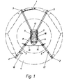
- Fig. 1 shows the snow chain according to the invention during the application
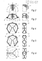
- Fig. 2 to 6 show schematically the different positions of the snow chain during the application
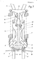
- Fig. 7 shows the spring device according to the invention.
- Fig. 1 essentially only the outer side chain of the snow chain can be seen.
- the inner side chain is essentially symmetrical on the inside of the tire (not visible).
- the ends of the side chains are attached to two L-shaped brackets 2 (hereinafter called outer brackets).
- the L-shape of the bracket 2 can best be seen in the right-hand part of FIG. 2.
- All brackets 2, 3 are rotatably mounted on a base plate 16.
- the assembly is shown schematically in FIGS. 2 to 6.
- the brackets 2, 3 are folded over the wheel 4; the snow chain 1 hangs down as a bundle (Fig. 2).
- the outer brackets 2 (Fig. 3) and then also the inner brackets 3 (Fig. 4) are fanned out. Since the outer brackets 2 are longer than the inner brackets 3, the brackets 2, 3 do not touch the tire 4 during this process. Only when they are fully tensioned (FIG. 6) do they rest on the tire 4.
- the center of the bearings of the brackets 2, 3 on the base plate 16 is then outside the wheel axis.
- the gear 19, which meshes with the toothing of the guide rod 13, is used to tension the springs. If the gear wheel 19 is turned counterclockwise by means of an actuating device (not shown), the bar 12 is pushed upwards and the springs are tensioned.
- the crossbar 10 fastened to the guide rod together with the hook 11 serves to fix the beam in the tensioned position. This hook can be rotated about a shaft 20.
- the hook 11 engages behind the crossbar 10 and thus fixes the guide rod 13 together with the beam 12.
- the hook 11 only has to be turned a little around the shaft 20 so that the springs can be relaxed again.
- a force in the direction of arrow 5 acts on the outer brackets 2 through the cables 15, ie the outer brackets are pressed against one another.
Landscapes
- Engineering & Computer Science (AREA)
- Mechanical Engineering (AREA)
- Devices For Conveying Motion By Means Of Endless Flexible Members (AREA)
- Buildings Adapted To Withstand Abnormal External Influences (AREA)
- Materials Applied To Surfaces To Minimize Adherence Of Mist Or Water (AREA)
- Cleaning Of Streets, Tracks, Or Beaches (AREA)
- Valve Device For Special Equipments (AREA)
- Control Of Eletrric Generators (AREA)
- Transmission Devices (AREA)
- Vehicle Body Suspensions (AREA)
Applications Claiming Priority (2)
| Application Number | Priority Date | Filing Date | Title |
|---|---|---|---|
| AT3558/85 | 1985-12-09 | ||
| AT0355885A AT386161B (de) | 1985-12-09 | 1985-12-09 | Gleitschutzkette |
Publications (2)
| Publication Number | Publication Date |
|---|---|
| EP0226571A2 true EP0226571A2 (fr) | 1987-06-24 |
| EP0226571A3 EP0226571A3 (fr) | 1988-10-19 |
Family
ID=3552173
Family Applications (1)
| Application Number | Title | Priority Date | Filing Date |
|---|---|---|---|
| EP86890335A Withdrawn EP0226571A3 (fr) | 1985-12-09 | 1986-12-09 | Chaíne anti-neige |
Country Status (9)
| Country | Link |
|---|---|
| EP (1) | EP0226571A3 (fr) |
| JP (1) | JPS62187604A (fr) |
| AT (1) | AT386161B (fr) |
| CS (1) | CS258146B2 (fr) |
| DD (1) | DD250901A5 (fr) |
| FI (1) | FI865012A (fr) |
| HU (1) | HU197256B (fr) |
| NO (1) | NO864929L (fr) |
| SU (1) | SU1494858A3 (fr) |
Cited By (5)
| Publication number | Priority date | Publication date | Assignee | Title |
|---|---|---|---|---|
| WO1995025643A1 (fr) * | 1994-03-24 | 1995-09-28 | Georges Thioliere | Dispositif de montage rapide de chaines a neige pour pneumatiques de vehicules |
| FR2758294A1 (fr) * | 1997-01-13 | 1998-07-17 | Gilbert Bobeda | Dispositif antiderapant pour roues de vehicules automobiles a fermeture automatique |
| FR2977832A1 (fr) * | 2011-07-12 | 2013-01-18 | Patrick Muti | Chaines a neige a montage rapide |
| FR2992900A1 (fr) * | 2012-07-03 | 2014-01-10 | Nicolas Raoul Morin | Equipement automobile de type "chaine a neige" a montage rapide destine a favoriser l'adherence des roues motrices sur chaussee enneigee |
| EP3173262A1 (fr) * | 2015-11-25 | 2017-05-31 | RUD Ketten Rieger & Dietz GmbH u. Co. KG | Dispositif antidérapant comprenant un lien souple guidé sur la bande de roulement et un moufle pour le lien souple |
Families Citing this family (2)
| Publication number | Priority date | Publication date | Assignee | Title |
|---|---|---|---|---|
| JP4738093B2 (ja) * | 2005-08-11 | 2011-08-03 | 鉦治 二村 | タイヤの滑止め装置 |
| DE102012102231A1 (de) * | 2012-03-16 | 2013-09-19 | Erlau Ag | Gleitschutzkette mit seitenstabilen Führungsketten |
Citations (7)
| Publication number | Priority date | Publication date | Assignee | Title |
|---|---|---|---|---|
| CH556251A (de) * | 1973-06-27 | 1974-11-29 | Stamm Robert | Schneekette. |
| DE2414511A1 (de) * | 1973-06-08 | 1975-01-02 | Monge Antonio C | Vorrichtung aus gelenkigen anti-rutschklammern fuer automobile |
| AT324864B (de) * | 1972-07-07 | 1975-09-25 | Ferdinand Freiherr V Helldorf | Kupplung oder schnellverschluss für ketten für fahrzeuge aller art |
| DE2721969A1 (de) * | 1976-05-14 | 1977-12-01 | Giancarlo Simoncelli | Schneeschutzvorrichtung fuer kraftfahrzeuge |
| DE2903236A1 (de) * | 1979-01-29 | 1980-07-31 | Erich Dr Baum | Schneekette |
| US4237951A (en) * | 1979-04-19 | 1980-12-09 | Jay Dirks | Industrial tire chain tightener |
| DE3146430A1 (de) * | 1980-12-03 | 1982-08-12 | Norbert Dipl.-Ing. 1190 Wien Kainz | Gleitschutzkette fuer kraftfahrzeugreifen |
Family Cites Families (3)
| Publication number | Priority date | Publication date | Assignee | Title |
|---|---|---|---|---|
| CH525103A (de) * | 1971-03-25 | 1972-07-15 | Rueegg August | Lösbarer Gleitschutz für Kraftfahrzeugräder |
| AT317012B (de) * | 1972-07-20 | 1974-08-12 | Elkem Spigerverket As | Vorrichtung zum Anbringen und Befestigen von Greifbügeln auf Fahrzeugrädern |
| DE2742519A1 (de) * | 1977-09-21 | 1979-03-29 | Sketec Vesuv | Anfahrhilfe fuer kraftfahrzeugreifen |
-
1985
- 1985-12-09 AT AT0355885A patent/AT386161B/de not_active IP Right Cessation
-
1986
- 1986-12-08 NO NO864929A patent/NO864929L/no unknown
- 1986-12-08 DD DD86297244A patent/DD250901A5/de unknown
- 1986-12-08 CS CS869007A patent/CS258146B2/cs unknown
- 1986-12-08 SU SU864028640A patent/SU1494858A3/ru active
- 1986-12-09 HU HU865128A patent/HU197256B/hu not_active IP Right Cessation
- 1986-12-09 FI FI865012A patent/FI865012A/fi not_active IP Right Cessation
- 1986-12-09 EP EP86890335A patent/EP0226571A3/fr not_active Withdrawn
- 1986-12-09 JP JP61291704A patent/JPS62187604A/ja active Pending
Patent Citations (7)
| Publication number | Priority date | Publication date | Assignee | Title |
|---|---|---|---|---|
| AT324864B (de) * | 1972-07-07 | 1975-09-25 | Ferdinand Freiherr V Helldorf | Kupplung oder schnellverschluss für ketten für fahrzeuge aller art |
| DE2414511A1 (de) * | 1973-06-08 | 1975-01-02 | Monge Antonio C | Vorrichtung aus gelenkigen anti-rutschklammern fuer automobile |
| CH556251A (de) * | 1973-06-27 | 1974-11-29 | Stamm Robert | Schneekette. |
| DE2721969A1 (de) * | 1976-05-14 | 1977-12-01 | Giancarlo Simoncelli | Schneeschutzvorrichtung fuer kraftfahrzeuge |
| DE2903236A1 (de) * | 1979-01-29 | 1980-07-31 | Erich Dr Baum | Schneekette |
| US4237951A (en) * | 1979-04-19 | 1980-12-09 | Jay Dirks | Industrial tire chain tightener |
| DE3146430A1 (de) * | 1980-12-03 | 1982-08-12 | Norbert Dipl.-Ing. 1190 Wien Kainz | Gleitschutzkette fuer kraftfahrzeugreifen |
Cited By (8)
| Publication number | Priority date | Publication date | Assignee | Title |
|---|---|---|---|---|
| WO1995025643A1 (fr) * | 1994-03-24 | 1995-09-28 | Georges Thioliere | Dispositif de montage rapide de chaines a neige pour pneumatiques de vehicules |
| FR2717744A1 (fr) * | 1994-03-24 | 1995-09-29 | Thioliere Georges | Dispositif de montage rapide de chaines à neige pour pneumatiques de véhicules. |
| US5785783A (en) * | 1994-03-24 | 1998-07-28 | Thioliere; Georges | Device for quickly fitting snow chains to vehicle tires |
| FR2758294A1 (fr) * | 1997-01-13 | 1998-07-17 | Gilbert Bobeda | Dispositif antiderapant pour roues de vehicules automobiles a fermeture automatique |
| FR2977832A1 (fr) * | 2011-07-12 | 2013-01-18 | Patrick Muti | Chaines a neige a montage rapide |
| FR2992900A1 (fr) * | 2012-07-03 | 2014-01-10 | Nicolas Raoul Morin | Equipement automobile de type "chaine a neige" a montage rapide destine a favoriser l'adherence des roues motrices sur chaussee enneigee |
| FR2992901A1 (fr) * | 2012-07-03 | 2014-01-10 | Nicolas Raoul Morin | Equipement automobile de type chaine a neige a montage rapide destine a favoriser l adherence des roues motrices sur chaussee enneigee |
| EP3173262A1 (fr) * | 2015-11-25 | 2017-05-31 | RUD Ketten Rieger & Dietz GmbH u. Co. KG | Dispositif antidérapant comprenant un lien souple guidé sur la bande de roulement et un moufle pour le lien souple |
Also Published As
| Publication number | Publication date |
|---|---|
| HU197256B (en) | 1989-03-28 |
| FI865012A (fi) | 1987-06-10 |
| NO864929L (no) | 1987-06-10 |
| NO864929D0 (no) | 1986-12-08 |
| SU1494858A3 (ru) | 1989-07-15 |
| HUT46267A (en) | 1988-10-28 |
| AT386161B (de) | 1988-07-11 |
| JPS62187604A (ja) | 1987-08-17 |
| DD250901A5 (de) | 1987-10-28 |
| CS258146B2 (en) | 1988-07-15 |
| ATA355885A (de) | 1987-12-15 |
| FI865012A0 (fi) | 1986-12-09 |
| EP0226571A3 (fr) | 1988-10-19 |
Similar Documents
| Publication | Publication Date | Title |
|---|---|---|
| DE69500037T2 (de) | Vorrichtung zum Tragen von Gegenständen, insbesondere Fahrrädern, auf der Hinterseite eines Kraftfahrzeuges | |
| CH635036A5 (de) | Verstellbare rueckenlehne eines sitzes. | |
| DE19708756A1 (de) | Spannschloß | |
| DE69220924T2 (de) | Vorrichtung zum handhaben eines fahrzeugrades | |
| DE29606353U1 (de) | Verzurrvorrichtung | |
| EP0226571A2 (fr) | Chaîne anti-neige | |
| DE2259989C2 (de) | Vorrichtung zur Stabilisierung der Lenkung von Lastzügen | |
| DE2608190A1 (de) | Netz- oder kettenartige, auf fahrzeugraeder montierbare gleitschutzvorrichtung | |
| DE102004032153B3 (de) | Fahnenmast mit einer Hissvorrichtung | |
| DE2356299C3 (de) | Behälter, insbesondere für Fahrzeuge, mit einem verriegelbaren Deckel | |
| DE3844491C1 (fr) | ||
| DE8534636U1 (de) | Vorrichtung zur Befestigung von Dachlasten | |
| EP0687642B1 (fr) | Dispositif pour emmagasiner et aussi pour enrouler et dérouler un élément allongé flexible | |
| DE3837343A1 (de) | Aufspreizsicherungsvorrichtung fuer ein dreibeiniges instrumentenstativ | |
| EP0037512A1 (fr) | Crampon anti-dérapant pour roues motrices de véhicules | |
| CH677215A5 (en) | Snow chain with rigid retainer fitted behind wheel - has two separate chains, to cover wheel section against ground during assembly, pulled into place by spring when wheel moves | |
| DE6601875U (de) | Rolladen | |
| DE2655581C2 (de) | Seilzugvorrichtung für die Spannseile eines rollbaren Öffnungsabschlusses | |
| DE3122512A1 (de) | Fahrzeugreifen-schneekette | |
| DE8802944U1 (de) | Spannvorrichtung | |
| DE102015114124A1 (de) | Lastenträger für eine Deichsel eines Fahrzeuganhängers | |
| DE69212954T2 (de) | Anhakungsvorrichtung für Förderungsvorrichtung von trapezförmigen Behältern | |
| DE4427508A1 (de) | Zugmittelgetriebe mit einer Spannvorrichtung | |
| EP0226535A1 (fr) | Store tout-temps | |
| DE1206748B (de) | Wechselgetriebe mit Kettenumschaltung fuer Fahrraeder od. dgl. |
Legal Events
| Date | Code | Title | Description |
|---|---|---|---|
| PUAI | Public reference made under article 153(3) epc to a published international application that has entered the european phase |
Free format text: ORIGINAL CODE: 0009012 |
|
| AK | Designated contracting states |
Kind code of ref document: A2 Designated state(s): AT BE CH DE ES FR GB GR IT LI LU NL SE |
|
| PUAL | Search report despatched |
Free format text: ORIGINAL CODE: 0009013 |
|
| AK | Designated contracting states |
Kind code of ref document: A3 Designated state(s): AT BE CH DE ES FR GB GR IT LI LU NL SE |
|
| STAA | Information on the status of an ep patent application or granted ep patent |
Free format text: STATUS: THE APPLICATION IS DEEMED TO BE WITHDRAWN |
|
| 18D | Application deemed to be withdrawn |
Effective date: 19890517 |