EP0216035B1 - Analysenwaage - Google Patents
Analysenwaage Download PDFInfo
- Publication number
- EP0216035B1 EP0216035B1 EP86109104A EP86109104A EP0216035B1 EP 0216035 B1 EP0216035 B1 EP 0216035B1 EP 86109104 A EP86109104 A EP 86109104A EP 86109104 A EP86109104 A EP 86109104A EP 0216035 B1 EP0216035 B1 EP 0216035B1
- Authority
- EP
- European Patent Office
- Prior art keywords
- drive
- analytical balance
- electric motor
- weighing
- friction wheel
- Prior art date
- Legal status (The legal status is an assumption and is not a legal conclusion. Google has not performed a legal analysis and makes no representation as to the accuracy of the status listed.)
- Expired - Lifetime
Links
- 238000005303 weighing Methods 0.000 claims description 22
- 238000006073 displacement reaction Methods 0.000 claims 1
- 238000000034 method Methods 0.000 description 6
- 238000001514 detection method Methods 0.000 description 2
- 235000017399 Caesalpinia tinctoria Nutrition 0.000 description 1
- 241000388430 Tara Species 0.000 description 1
- 238000013459 approach Methods 0.000 description 1
- 230000005540 biological transmission Effects 0.000 description 1
- 238000010073 coating (rubber) Methods 0.000 description 1
- 238000011109 contamination Methods 0.000 description 1
- 230000008878 coupling Effects 0.000 description 1
- 238000010168 coupling process Methods 0.000 description 1
- 238000005859 coupling reaction Methods 0.000 description 1
- 230000001419 dependent effect Effects 0.000 description 1
- 230000000694 effects Effects 0.000 description 1
- 230000006870 function Effects 0.000 description 1
- 239000011521 glass Substances 0.000 description 1
- 239000002184 metal Substances 0.000 description 1
- 230000007935 neutral effect Effects 0.000 description 1
- 230000003287 optical effect Effects 0.000 description 1
- 238000012827 research and development Methods 0.000 description 1
- 239000000126 substance Substances 0.000 description 1
- 230000001360 synchronised effect Effects 0.000 description 1
- 230000001960 triggered effect Effects 0.000 description 1
- 238000002604 ultrasonography Methods 0.000 description 1
Images

Classifications
-
- G—PHYSICS
- G01—MEASURING; TESTING
- G01G—WEIGHING
- G01G21/00—Details of weighing apparatus
- G01G21/28—Frames, Housings
- G01G21/286—Frames, Housings with windshields
-
- G—PHYSICS
- G01—MEASURING; TESTING
- G01G—WEIGHING
- G01G21/00—Details of weighing apparatus
- G01G21/28—Frames, Housings
- G01G21/283—Details related to a user interface
-
- G—PHYSICS
- G01—MEASURING; TESTING
- G01G—WEIGHING
- G01G21/00—Details of weighing apparatus
- G01G21/30—Means for preventing contamination by dust
Definitions
- the invention is based on an analytical balance with a weighing chamber that can be closed by movable housing parts.
- At least one of the movable housing parts When weighing a substance on an analytical balance with a lockable weighing chamber, at least one of the movable housing parts must be opened and then closed again to load the balance.
- steps For single dosing of a weighing sample, e.g. with a spatula, at least fifteen steps have to be carried out with the known scales. Namely: open the housing part (window), place the container on the weighing pan, close the housing part, tare, grasp the spatula, put the weighing object on the spatula, open the housing part, dose, remove the spatula from the weighing chamber, close the draft shield, wait for the result, open the draft shield, remove the container, draft shield shut down.
- the opening and closing of the draft shield always requires the removal of either the container or the spatula, both of which the operator already has in his hands at the start of the weighing and must be removed after the weighing.
- the handles are cumbersome and time-consuming, especially since the hand regularly opens / closes the weighing chamber, which also guides the spatula.
- the known device does not offer a solution for consistently reducing the handles.
- the invention has for its object to eliminate the shortcomings in the operation of an analytical balance of the type mentioned and to free the operator from manual execution of the required opening and closing operations of the movable housing parts.
- this object is achieved in that at least one of the movable housing parts can be coupled to a drive which can be actuated in a contactless manner by a control device embodied in memory states of a computer which can be queried in accordance with a predefinable program.
- non-contact sensors mentioned in the following description e.g. voice-controlled sensors that not only trigger opening and closing in different languages or with various words, but also other functions, e.g. taring can be initiated without having to clear your hands.
- an analytical balance 1 with a display field 3 on an operating panel 4, the weighing chamber 5 and two movable housing parts 7 closing the weighing chamber 5 on the side, a housing part 8 covering the weighing chamber 5 at the top, and the housing 9 with the mechanical and electronic units the analytical balance 1 is shown.
- the housing parts 7 and 8 can be opened and closed by a drive 14 individually or together or in such a way that a vertical housing part 7 together with the horizontal housing part 8 or, if possible, is operated with the front housing part, provided the drive elements are adapted accordingly.
- a control device for the drive 14 is embodied in the memory states of a computer 13. At appropriate points in a program sequence that is input or can be entered into the computer, the computer then recognizes that it must now output a control signal for opening or closing. This is particularly important for more sophisticated systems, for example for routine series weighing.
- a voice-controlled sensor 11 e.g. a microphone is used, which is connected to the computer 13, which processes voice commands and in control sequences for the energy supply of the drive 14 of the housing parts 7 and the taring and the like. converts.
- a proximity sensor 15 e.g. an infrared or ultrasonic sensor, attached to the analytical balance 1. Its reception range is preferably limited to a specific sector S, so that the signals for actuating the housing parts 7 and 8 only just when an object enters, e.g. the hand, the goods to be weighed or the gripper 43 of a robot 39 is triggered into sector S, but not if other activities in the area of the balance, e.g. can be exercised on their control panel 4.
- the infrared sensor responds to the hand warmth, but not to objects that enter its sensor area.
- the voice-controlled sensor 11 and / or the proximity sensor 15 can of course also be arranged on a holder set up separately from the scale housing, e.g. on the computer 13.
- the movable housing parts 7 and 8 are conventionally easily slidably mounted in guide grooves in the housing 9.
- the housing parts 7 and 8 can be brought into connection with the drive 14 (only shown on the left housing part 7).
- the housing parts 7 and 8 are moved backwards to open the weighing chamber 5 and forwards to close them, the drive 14 being frictionally connected to the respective housing parts 7 and 8 during pushing and being able to be disconnected therefrom when the respective end position "opens" "or” closed "is reached.
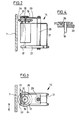
- FIG. 1 An embodiment of a decouplable drive 14 is shown in Figures 2 to 4.
- the drive 14 consists essentially of an electric motor 17 which is attached to an angular spring 21.
- a bolt 25 Parallel to the rotor shaft 19 of the electric motor 17, a bolt 25 is rigidly connected to a base plate 27 to which the spring 21 is also screwed.
- a guide plate 29 is fastened with a V-shaped guide slot 31, through which the rotor shaft 19 projects.
- a metal friction wheel 35 sits on the rotor shaft 19 above the guide plate 29 and a friction wheel 33 covered with a rubber coating or an O-ring 34 beneath the guide plate 29. The diameter of the friction wheel 33 is larger than that of the friction wheel 35.
- the width of the guide slot 31 is greater than the diameter of the rotor shaft 19.
- the tensioning force of the spring 21 causes the friction wheel 35 to rest against a web 37 running parallel to the guide slot 31 in the neutral starting position (FIG. 4); the friction wheel 33 does not touch the adjacent housing part 7 in this position (FIG. 3).
- the base plate 27 of the drive 14 is attached to the housing 9 of the scale 1, and the electric motor 17 is connected to the computer 13.
- a scale 1 equipped with a contactlessly operating sensor 11 or 15 is operated in the manner described below:
- the scale 1 has a standby circuit for the computer 13, this can already be switched on by means of a spoken code word correspondingly stored in the computer 13. Then another code word, e.g. "Open” or “open”, the housing part and / or both housing parts 7 and 8 are opened and the metering is carried out. With the code word “close” or “closed”, the housing part 7 or 8 is closed again and the weighing is carried out.
- the opening takes place when the moving housing part 7 or 8 is approached, and the closing takes place after the operator's hand and / or the tool, e.g. the spatula from which sensitive area S has been removed.
- a foot pedal 37 can also be used to trigger the commands.
- signals from a computer 41 controlling the robot 39 can also be used.
- Such a control enables a command to be opened to open the housing parts 7 or 8 even before the gripper 43 of the robot 39 begins to move towards the weighing chamber 5, as a result of which waiting times in front of the scale 1 can be avoided or the working time can be shortened.
- a "soft key” 45 can also be provided on the control panel 4 of the scale 1, on which e.g. lights up when the weighing room 5 is closed and "closed" when the weighing room 5 is open. In this way, the operator always knows which is the next step. This can be particularly important if the housing parts 7 and 8 are only opened as far as is necessary. A partial opening can be particularly advantageous if the robot 39 feeds the scale.
- the latter After evaluating the signals supplied to the computer 13 by the sensors 11 or 15, the computer 41, the foot pedal 31 or the soft key 45, the latter starts the electric motor 17 in the corresponding direction of rotation.
- the friction wheel 35 rolls on the web 37 and moves the elastically suspended electric motor 17 in the positive direction of rotation (counterclockwise) in the guide slot 31 in the direction of arrow A.
- the friction wheel 33 now comes into frictional contact with the housing part 7 or 8 and moves it Direction of arrow B.
- the spring energy stored in the O-ring squeezed during the drive process pushes the friction wheel 35 back into the starting position, and at the same time the frictional friction connection to the housing part 7 or 8 is released, so that the housing part 7 or 8 can be operated by hand.
Landscapes
- Physics & Mathematics (AREA)
- General Physics & Mathematics (AREA)
- Engineering & Computer Science (AREA)
- Human Computer Interaction (AREA)
- Weight Measurement For Supplying Or Discharging Of Specified Amounts Of Material (AREA)
- Automatic Analysis And Handling Materials Therefor (AREA)
- Steroid Compounds (AREA)
- Power-Operated Mechanisms For Wings (AREA)
- Sampling And Sample Adjustment (AREA)
Description
- Die Erfindung geht aus von einer Analysenwaage mit einem durch bewegliche Gehäuseteile verschließbaren Wägeraum.
- Beim Wägen einer Substanz auf einer Analysenwaage mit einem verschließbaren Wägeraum ist für die Beschickung der Waage mindestens einer der beweglichen Gehäuseteile zu öffnen und danach wieder zu schließen. Zum einmaligen Dosieren eines Wägegutes, z.B. mit einem Spachtel, müssen bei den bekannten Waagen mindestens fünfzehn Handgriffe vorgenommen werden. Nämlich: Gehäuseteil (Fenster) öffnen, Gefäß auf Waageschale stellen, Gehäuseteil schließen, Tarieren, Spachtel ergreifen, Wägegut auf Spachtel bringen, Gehäuseteil öffnen, Eindosieren, Spachtel aus dem Wägeraum entnehmen, Windschutz schließen, Resultat abwarten, Windschutz öffnen, Gefäß herausnehmen, Windschutz schließen.
- Das Öffnen und Schließen des Windschutzes, insgesamt sechsmal, erfordert immer das Weglegen entweder des Gefäßes oder des Spachtels, welche beide die Bedienungsperson zu Beginn der Wägung bereits in den Händen trägt und nach der Wägung wieder entfernen muß. Die Handgriffe sind umständlich und zeitraubend, zumal regelmäßig die Hand den Wägeraum öffnet/schließt, die auch den Spachtel führt.
- Aus der Schweizer Patentschrift 559 901 ist eine Waage der eingangs genannten Art bekannt, bei der die beiden seitlichen Gehäuseteile (Schiebefenster) mit einer Koppelungseinrichtung zum synchronen Öffnen und Schließen miteinander verbunden sind, wobei die Bedienung sowohl mit der linken als auch mit der rechten Hand möglich ist. Auf diese Weise wird erreicht, daß jeweils eine Hand frei bleibt für eine weitere Manipulation oder zum Halten eines Gegenstandes, und daß gleichzeitig mit der anderen Hand das Schiebefenster geöffnet werden kann.
- Eine Lösung zur konsequenten Verringerung der Handgriffe bietet die bekannte Vorrichtung nicht.
- Es ist bekannt (WO-82/02 536), an der in Schließrichtung weisenden Kante einer Aufzugstür mehrere kapazitive, optische oder auf Ultraschallaussendung und Reflexion beruhende Annäherungsfühler vorzusehen und die Erfassungssignale dieser Annäherungsfühler in Differenzialverstärkern miteinander zu vergleichen, um beim Auftreten eines Unterschiedes in den Erfassungssignalen dieser Annäherungsfühler die Türschließbewegung der Aufzugstür zu unterbrechen. Hierdurch soll die Unterbrechung der Türschließbewegung unabhängig von Nullpunktsignalen der einzelnen Näherungsfühler sichergestellt werden. Diese bekannte Anordnung dient somit lediglich einer sicheren Unterbrechung der Schließbewegung der Aufzugstür bei einer Personenannäherung, ermöglicht jedoch keine gezielte Steuerung des Öffnungs- und Schließvorgangs der Aufzugstür gemäß einem bestimmten vorgegebenen Betriebsablauf.
- Auch ist es grundsätzlich bekannt, die automatische Spracherkennung zur Steuerung eines Fahrzeuges durch Behinderte, insbesondere zum Öffnen und Schließen der Fenster, einzusetzen (Siemens Forschungs- und Entwicklungsberichte Band 10, 1981, Nr. 5, Seite 316-322). Konkrete Anhaltspunkte für die Steuerung der speziellen Betriebsabläufe bei einer Analysenwaage sind daraus jedoch nicht zu gewinnen.
- Der Erfindung liegt die Aufgabe zugrunde, die Unzulänglichkeiten bei der Bedienung einer Analysenwaage der eingangs genannten Art zu beseitigen und die Bedienungsperson von einer manuellen Durchführung der erforderlichen Öffnungs- und Schließvorgänge der beweglichen Gehäuseteile zu befreien.
- Erfindungsgemäß wird diese Aufgabe dadurch gelöst, daß mindestens einer der beweglichen Gehäuseteile mit einem Antrieb koppelbar ist, der durch eine in nach einem jeweils vorgebbaren Programm abfragbaren Speicherzuständen eines Rechners verkörperte Ansteuerungseinrichtung berührungslos betätigbar ist.
- Die damit erreichten Vorteile sind im wesentlichen darin zu sehen, daß die Bedienungsperson das Öffnen und Schließen der Gehäuseteile berührungslos bewirken kann, d.h. ohne dazu die Hände freimachen zu müssen. Sie spart dadurch mindestens sechs Arbeitsvorgänge bei jedem Dosiervorgang und vermeidet zudem eine allfällige Verunreinigung der Waage und/oder des Wägegutes oder des Gefäßes und des Spachtels beim zwischenzeitlichen Absetzen auf die Arbeitsfläche.
- Weitere vorteilhafte Ausgestaltungen sind in den kennzeichnenden Merkmalen der abhängigen Ansprüche enthalten. Dagegen sind die in der folgenden Beschreibung noch erwähnten berührungslosen Sensoren, z.B. sprachgesteuerte Sensoren, mit denen nicht nur in verschiedenen Sprachen oder mit diversen Worten das Öffnen und Schließen ausgelöst, sondern auch weitere Funktionen, z.B. das Tarieren, eingeleitet werden können, ohne daß dazu die Hände freigemacht werden müssen, nicht beansprucht.
- Ein Ausführungsbeispiel der Erfindung wird nachfolgend anhand von Zeichnungen beschrieben. Es zeigen:
- Figur 1 eine schematische Darstellung einer Waage,
- Figur 2 eine Seitenansicht eines Antriebes für den Gehäuseteil,
- Figur 3 einen Grundriß des Antriebes in Figur 2 und Figur 4 ein Detail des Antriebes.
- In der Figur 1 ist eine Analysenwaage 1 mit einem Anzeigefeld 3 auf einem Bedienungstableau 4, dem Wägeraum 5 und zwei seitlich den Wägeraum 5 abschließenden beweglichen Gehäuseteilen 7, einem den Wägeraum 5 oben überdeckenden Gehäuseteil 8, sowie dem Gehäuse 9 mit den mechanischen und elektronischen Aggregaten der Analysenwaage 1 dargestellt.
- Das Öffnen und Schließen der Gehäuseteile 7 bzw. 8 kann durch einen Antrieb 14 je einzeln oder gemeinsam oder in der Weise erfolgen, daß jeweils ein vertikaler Gehäuseteil 7 zusammen mit dem horizontalliegenden Gehäuseteil 8 oder, sofern möglich, mit dem vorneliegenden Gehäuseteil betätigt wird, sofern die Antriebsorgane entsprechend angepaßt sind.
- Eine Ansteuerungseinrichtung für den Antrieb 14 ist in Speicherzuständen eines Rechners 13 verkörpert. An entsprechenden Stellen eines dem Rechner eingegebenen bzw. eingebbaren Programmablaufs erkennt dieser dann, daß er jetzt ein Steuersignal zum Öffnen oder Schließen ausgeben muß. Dies ist bedeutsam besonders bei anspruchsvolleren Systemen, beispielsweise für routinemäßige Serienwägungen.
- Auf der Vorderseite der Waage 1 ist zudem ein sprachgesteuerter Sensor 11, z.B. ein Mikrofon, eingesetzt, der mit dem Rechner 13 verbunden ist, welcher Sprachbefehle verarbeitet und in Steuersequenzen für die Energieversorgung des Antriebes 14 der Gehäuseteile 7 und die Tarierung u.ä. umwandelt.
- Anstelle des sprachgesteuerten Sensors 11 oder zusätzlich zu diesem kann ein Näherungssensor 15, z.B. ein Infrarot- oder Ultraschallsensor, an der Analysenwaage 1 angebracht sein. Vorzugsweise ist dessen Empfangsbereich auf einen bestimmten Sektor S begrenzt, damit die Signale zur Betätigung der Gehäuseteile 7 bzw. 8 nur gerade bei Eintritt eines Gegenstandes, z.B. der Hand, des Wägegutes oder des Greifers 43 eines Roboters 39, in den Sektor S ausgelöst wird, nicht aber, wenn andere Tätigkeiten im Bereich der Waage, z.B. an deren Bedienungstableau 4, ausgeübt werden. Der Infrarotsensor spricht auf die Handwärme, nicht aber auf Gegenstände an, die in dessen Sensorbereich eintreten.
- Der sprachgesteuerte Sensor 11 und/oder der Näherungssensor 15 können selbstverständlich auch auf einem vom Waagengehäuse getrennt aufgestellten Halter angeordnet sein, z.B. auf dem Rechner 13.
- Die beweglichen Gehäuseteile 7 und 8, üblicherweise aus Glas hergestellt, sind in herkömmlicher Weise in Führungsnuten im Gehäuse 9 leicht verschiebbar gelagert.
- Die Gehäuseteile 7 bzw. 8 können in Verbindung mit dem Antrieb 14 (nur am linken Gehäuseteil 7 eingezeichnet) gebracht werden. Die Gehäuseteile 7 bzw. 8 werden zum Öffnen des Wägeraumes 5 nach hinten und zum Schließen nach vorne bewegt, wobei der Antrieb 14 während des Schiebens reibschlüssig mit dem jeweiligen Gehäuseteil 7 bzw. 8 verbunden und von diesem abkoppelbar ist, wenn die jeweilige Endstellung "geöffnet" oder "geschlossen" erreicht ist.
- Eine Ausführungsform eines abkoppelbaren Antriebes 14 ist in den Figuren 2 bis 4 dargestellt.
- Der Antrieb 14 besteht im wesentlichen aus einem Elektromotor 17, der an einer winkelförmig ausgebildeten Feder 21 befestigt ist. Parallel zur Rotorwelle 19 des Elektromotors 17 ist ein Bolzen 25 starr mit einer Grundplatte 27 verbunden, an der auch die Feder 21 angeschraubt ist. Am oberen Ende des Bolzens 25 ist eine Führungsplatte 29 mit einem v-förmigen Führungsschlitz 31 befestigt, durch welchen die Rotorwelle 19 hindurchragt. Auf der Rotorwelle 19 sitzt oberhalb der Führungsplatte 29 ein metallenes Reibrad 35 und unterhalb der Führungsplatte 29 ein mit einer Gummierung oder einem O-Ring 34 belegtes Reibrad 33. Der Durchmesser des Reibrades 33 ist größer als derjenige des Reibrades 35.
- Die Breite des Führungsschlitzes 31 ist größer als der Durchmesser der Rotorwelle 19. Durch die Spannkraft der Feder 21 liegt das Reibrad 35 in der neutralen Ausgangsstellung an einem parallel zum Führungsschlitz 31 verlaufenden Steg 37 an (Figur 4); das Reibrad 33 berührt bei dieser Stellung den anliegenden Gehäuseteil 7 nicht (Figur 3).
- Die Grundplatte 27 des Antriebes 14 ist am Gehäuse 9 der Waage 1 befestigt, und der Elektromotor 17 ist mit dem Rechner 13 verbunden.
- Eine mit einem berührungslos arbeitenden Sensor 11 bzw. 15 ausgerüstete Waage 1 wird in nachfolgend beschriebener Weise bedient:
- Wenn die Waage 1 eine Stand-by-Schaltung für den Rechner 13 aufweist, kann diese bereits durch ein im Rechner 13 entsprechend gespeichertes gesprochenes Codewort eingeschaltet werden. Anschließend kann durch ein weiteres Codewort, z.B. "öffnen" oder "auf", der Gehäuseteil und/oder beide Gehäuseteile 7 bzw. 8 geöffnet und das Eindosieren vorgenommen werden. Mit dem Codewort "schließen" oder "zu" wird der Gehäuseteil 7 bzw. 8 wieder geschlossen und die Wägung durchgeführt.
- Bei einer Waage mit einem Näherungssensor 15 erfolgt das Öffnen bei der Annäherung an den beweglichen Gehäuseteil 7 bzw. 8, und das Schließen, nachdem die Hand der Bedienungsperson und/oder das Werkzeug, z.B. der Spachtel, aus dem sensitiven Bereich S entfernt worden ist.
- Es ist auch möglich, durch einen Sprachbefehl, z.B. "Tara", das Tarieren der Waage auszulösen. Selbstverständlich können anstelle der deutschen Befehle auch solche in anderen Sprachen, ferner Befehle in verschiedenen Stimmlagen (Frauenstimmen oder Männerstimmen) eingegeben werden.
- Selbstverständlich kann auch ein Fußpedal 37 zum Auslösen der Befehle eingesetzt werden.
- Anstelle der Befehlsauslösung durch Sensoren 11 bzw. 15 oder durch ein Fußpedal 37 können auch Signale eines den Roboter 39 steuernden Computers 41 verwendet werden. Eine solche Aussteuerung ermöglicht eine Befehlsausgabe zum Öffnen der Gehäuseteile 7 bzw. 8 schon bevor der Greifer 43 des Roboters 39 sich gegen den Wägeraum 5 hin zu bewegen beginnt, wodurch Wartezeiten vor der Waage 1 vermieden bzw. die Arbeitszeit verkürzt werden können.
- Zur manuellen Bedienung des elektrischen Antriebes 14 kann auf dem Bedienungstableau 4 der Waage 1 auch ein "Soft-key" 45 vorgesehen werden, auf welchem z.B. bei geschlossenem Wägeraum 5 "auf" und bei geöffnetem Wägeraum 5 "zu" aufleuchtet. Die Bedienungsperson weiß auf diese Weise jederzeit, welches der nächste Schritt ist. Dies kann insbesondere auch dann wichtig sein, wenn die Gehäuseteile 7 bzw. 8 jeweils nur so weit geöffnet werden, wie dies gerade notwendig ist. Eine teilweise Öffnung kann speziell dann vorteilhaft sein, wenn die Beschickung der Waage durch den Roboter 39 erfolgt.
- Nach der Auswertung der von den Sensoren 11 bzw. 15, dem Computer 41, dem Fußpedal 31 oder dem Soft-key 45 dem Rechner 13 zugeführten Signale setzt dieser den Elektromotor 17 in der entsprechenden Drehrichtung in Gang. Das Reibrad 35 rollt dabei auf dem Steg 37 ab und bewegt den elastisch aufgehängten Elektromotor 17 bei positiver Drehrichtung (Gegenuhrzeigersinn) im Führungsschlitz 31 in Richtung des Pfeiles A. Das Reibrad 33 gelangt nun in Reibkontakt mit dem Gehäuseteil 7 bzw. 8 und bewegt diesen in Richtung des Pfeiles B. Sobald die Energiezufuhr zum Elektromotor 17 wieder unterbrochen wird, drückt die im während des Antriebsvorganges zusammengequetschten O-Ring gespeicherte Federenergie das Reibrad 35 in die Ausgangsstellung zurück, und gleichzeitig wird die kraftschlüssige Reibverbindung zum Gehäuseteil 7 bzw. 8 gelöst, so daß der Gehäuseteil 7 bzw. 8 von Hand bedient werden kann.
Claims (5)
Applications Claiming Priority (2)
| Application Number | Priority Date | Filing Date | Title |
|---|---|---|---|
| CH4056/85A CH667921A5 (de) | 1985-09-18 | 1985-09-18 | Analysenwaage. |
| CH4056/85 | 1985-09-18 |
Publications (3)
| Publication Number | Publication Date |
|---|---|
| EP0216035A2 EP0216035A2 (de) | 1987-04-01 |
| EP0216035A3 EP0216035A3 (en) | 1988-06-15 |
| EP0216035B1 true EP0216035B1 (de) | 1990-09-12 |
Family
ID=4268996
Family Applications (1)
| Application Number | Title | Priority Date | Filing Date |
|---|---|---|---|
| EP86109104A Expired - Lifetime EP0216035B1 (de) | 1985-09-18 | 1986-07-03 | Analysenwaage |
Country Status (5)
| Country | Link |
|---|---|
| US (1) | US4789034A (de) |
| EP (1) | EP0216035B1 (de) |
| JP (1) | JPH0629762B2 (de) |
| CH (1) | CH667921A5 (de) |
| DE (1) | DE3674120D1 (de) |
Cited By (2)
| Publication number | Priority date | Publication date | Assignee | Title |
|---|---|---|---|---|
| DE102008029418A1 (de) * | 2008-06-23 | 2009-12-24 | Bizerba Gmbh & Co. Kg | Verfahren zum Betrieb einer Ladenwaage |
| DE102008029419A1 (de) * | 2008-06-23 | 2009-12-24 | Bizerba Gmbh & Co. Kg | Ladenwaage |
Families Citing this family (35)
| Publication number | Priority date | Publication date | Assignee | Title |
|---|---|---|---|---|
| CH669257A5 (de) * | 1986-02-28 | 1989-02-28 | Mettler Instrumente Ag | Praezisionswaage. |
| JPS63180832A (ja) * | 1987-01-22 | 1988-07-25 | Power Reactor & Nuclear Fuel Dev Corp | 自動重量サンプリング装置 |
| USD309720S (en) | 1987-04-28 | 1990-08-07 | Mettler Instrumente Ag | Analytical balance |
| CH673528A5 (de) * | 1988-02-15 | 1990-03-15 | Mettler Instrumente Ag | |
| USD315525S (en) | 1988-04-08 | 1991-03-19 | Cobos S.A. | Scale |
| US4862978A (en) * | 1988-04-29 | 1989-09-05 | Borchard John S | Combination dust cover and air screen |
| DE3815626A1 (de) * | 1988-05-07 | 1989-11-16 | Sartorius Gmbh | Elektronische waage mit kalibriergewichtsschaltung |
| CH675480A5 (de) * | 1988-07-26 | 1990-09-28 | Mettler Toledo Ag | |
| US4821821A (en) * | 1988-09-12 | 1989-04-18 | Instruments for Research and Industry I2 R, Inc. | Electrostatically shielded laboratory balance |
| DE3919870C1 (de) * | 1989-06-19 | 1990-06-21 | Sartorius Gmbh, 3400 Goettingen, De | |
| CH680164A5 (de) * | 1990-05-23 | 1992-06-30 | Mettler Toledo Ag | |
| CH681391A5 (de) * | 1991-02-01 | 1993-03-15 | Mettler Toledo Ag | |
| JP2647585B2 (ja) * | 1991-11-28 | 1997-08-27 | 三菱電機株式会社 | 自動薄膜計測装置 |
| JP3026276B2 (ja) * | 1992-05-22 | 2000-03-27 | 本田技研工業株式会社 | 脚式移動ロボットの非常停止制御装置 |
| DE29805023U1 (de) * | 1998-03-19 | 1999-07-29 | Espig, Rainer, 97500 Ebelsbach | Wägesystem |
| US6166506A (en) * | 1998-06-19 | 2000-12-26 | Tregaskiss, Ltd. | Wireless safety clutch |
| DE19850416C1 (de) * | 1998-11-02 | 2000-05-11 | Sartorius Gmbh | Waage mit motorisch betätigtem Windschutz |
| CH694475A5 (de) * | 1999-07-08 | 2005-01-31 | Mettler Toledo Gmbh | Verfahren zum Betrieb einer Waage und Vorrichtung zur Durchführung des Verfahrens. |
| DE10213786A1 (de) * | 2002-03-27 | 2003-10-23 | Sartorius Gmbh | Analysenwaage mit motorisch bewegbarer Windschutztür |
| DE10308804A1 (de) * | 2002-06-14 | 2004-01-08 | Soehnle-Waagen Gmbh & Co. Kg | Waage |
| EP1526364B2 (de) * | 2003-10-21 | 2009-09-30 | Mettler-Toledo AG | Verfahren zum Betätigen einer Waage und Waage |
| JP2007212254A (ja) * | 2006-02-08 | 2007-08-23 | Shimadzu Corp | 電子天びん |
| JP2009014429A (ja) * | 2007-07-03 | 2009-01-22 | Seiko Epson Corp | 重量測定装置、液滴吐出装置及び重量測定方法 |
| US20110005842A1 (en) * | 2009-07-12 | 2011-01-13 | Frank Chan | Food Scale that measures specific volume and weight from preprogrammed densities while compiling nutritional data of used ingredients from stored data. |
| PL223292B1 (pl) * | 2012-09-10 | 2016-10-31 | Lewandowski Witold Radwag Wagi Elektroniczne | Mechanizm automatycznego otwierania drzwi komory ważenia wagi analitycznej |
| DE102013106014B4 (de) * | 2013-06-10 | 2016-02-18 | Bundesrepublik Deutschland, vertreten durch das Bundesministerium für Wirtschaft und Technologie, dieses vertreten durch den Präsidenten der BAM, Bundesanstalt für Materialforschung und -prüfung | Vorrichtung und Verfahren zur automatischen Bestückung einer Waage |
| EP2924401B1 (de) | 2014-03-28 | 2016-12-28 | Mettler-Toledo GmbH | Roboterbetätigte Türöffnungsvorrichtung für ein Windschutzgehäuse einer Analysenwaage |
| DE102015108102B4 (de) | 2015-05-22 | 2017-06-14 | Sartorius Lab Instruments Gmbh & Co. Kg | Wägevorrichtung |
| EP3510411A4 (de) * | 2016-09-11 | 2020-04-22 | ESI Source Solutions, LLC | Tischlaborvorrichtungautomatisierungssystem |
| EP3557200B1 (de) | 2018-04-17 | 2021-09-29 | Mettler-Toledo GmbH | Laborwaage mit motorisiertem windschutz |
| EP3578935B1 (de) * | 2018-06-07 | 2021-03-31 | Mettler-Toledo GmbH | Wiegevorrichtung mit beweglicher halterung |
| US20200075035A1 (en) * | 2018-08-30 | 2020-03-05 | Thomas Garth, III | Sound Shield Device |
| WO2021186559A1 (ja) * | 2020-03-17 | 2021-09-23 | 株式会社 エー・アンド・デイ | 天びん用風防 |
| JP7548146B2 (ja) | 2021-07-16 | 2024-09-10 | 株式会社島津製作所 | 電子天びん |
| EP4425121A1 (de) * | 2023-03-02 | 2024-09-04 | Mettler-Toledo GmbH | Wägevorrichtung, system mit der wägevorrichtung und verfahren zum ermitteln eines gewichts |
Family Cites Families (15)
| Publication number | Priority date | Publication date | Assignee | Title |
|---|---|---|---|---|
| US2468453A (en) * | 1938-04-12 | 1949-04-26 | Mallentjer Victor Bernar Marie | Reversible drive mechanism |
| US2614825A (en) * | 1948-01-23 | 1952-10-21 | Meopta Nat Corp | Precision balance |
| CH461121A (de) * | 1968-02-29 | 1968-08-15 | Mikrowa Fein Und Schnellwaagen | Feinwaage mit arretierbarem Wägemechanismus |
| CH559901A5 (en) * | 1974-03-22 | 1975-03-14 | Mettler Instrumente Ag | Analysis scales with weighing space divided by sliding windows - are closed and opened together by coupling device |
| DE2505890A1 (de) * | 1975-02-13 | 1976-09-02 | Zeiss Ikon Ag | Schluesselloses schloss |
| US4084149A (en) * | 1975-07-09 | 1978-04-11 | Diebold, Incorporated | Sonar actuated control device for positioning movable objects |
| JPS606280B2 (ja) * | 1977-03-24 | 1985-02-16 | 三菱電機株式会社 | 近接検出装置 |
| CH612503A5 (de) * | 1977-05-13 | 1979-07-31 | Mettler Instrumente Ag | |
| JPS56164127U (de) * | 1980-05-10 | 1981-12-05 | ||
| JPS5721682A (en) * | 1980-07-15 | 1982-02-04 | Matsushita Electric Works Ltd | Automatic door |
| JPS5721026A (en) * | 1980-07-15 | 1982-02-03 | Seiko Instr & Electronics | Electronic device |
| EP0070286B1 (de) * | 1981-01-26 | 1985-10-09 | Memco-Med Limited | Annäherungsdetektorkreis, insbesondere für eine aufzugstür |
| JPS57151773A (en) * | 1981-03-11 | 1982-09-18 | Nissan Motor | Automatic door lock apparatus |
| US4621452A (en) * | 1985-01-18 | 1986-11-11 | Deeg Wyman L | Powered sliding door safety system |
| CH669257A5 (de) * | 1986-02-28 | 1989-02-28 | Mettler Instrumente Ag | Praezisionswaage. |
-
1985
- 1985-09-18 CH CH4056/85A patent/CH667921A5/de not_active IP Right Cessation
-
1986
- 1986-05-19 JP JP61116018A patent/JPH0629762B2/ja not_active Expired - Fee Related
- 1986-07-03 DE DE8686109104T patent/DE3674120D1/de not_active Expired - Lifetime
- 1986-07-03 EP EP86109104A patent/EP0216035B1/de not_active Expired - Lifetime
-
1988
- 1988-01-26 US US07/148,128 patent/US4789034A/en not_active Expired - Lifetime
Cited By (2)
| Publication number | Priority date | Publication date | Assignee | Title |
|---|---|---|---|---|
| DE102008029418A1 (de) * | 2008-06-23 | 2009-12-24 | Bizerba Gmbh & Co. Kg | Verfahren zum Betrieb einer Ladenwaage |
| DE102008029419A1 (de) * | 2008-06-23 | 2009-12-24 | Bizerba Gmbh & Co. Kg | Ladenwaage |
Also Published As
| Publication number | Publication date |
|---|---|
| JPS6269124A (ja) | 1987-03-30 |
| DE3674120D1 (de) | 1990-10-18 |
| US4789034A (en) | 1988-12-06 |
| CH667921A5 (de) | 1988-11-15 |
| EP0216035A3 (en) | 1988-06-15 |
| EP0216035A2 (de) | 1987-04-01 |
| JPH0629762B2 (ja) | 1994-04-20 |
Similar Documents
| Publication | Publication Date | Title |
|---|---|---|
| EP0216035B1 (de) | Analysenwaage | |
| EP0226532B1 (de) | Elektrische Schaltzelle mit einem Verstellantrieb für ein verfahrbar angeordnetes Schaltgerät | |
| CH678361A5 (de) | ||
| EP2163461A2 (de) | Verfahren und Montagegerät zum Positionieren von Komponenten an/in Fahrzeugen | |
| DE102019127899A1 (de) | Werkzeugmaschine | |
| DE3911656A1 (de) | Pruefgeraet fuer die bremsanlage eines kraftfahrzeugs | |
| EP2924401B1 (de) | Roboterbetätigte Türöffnungsvorrichtung für ein Windschutzgehäuse einer Analysenwaage | |
| DE3321796C2 (de) | ||
| DE2952253A1 (de) | Voreinstellbare bremseinrichtung fuer eine zeichenmaschine | |
| DE69000915T2 (de) | Sich hin- und herbewegende ueberfuehrungsvorrichtung. | |
| EP2774724A1 (de) | Drehmomentwerkzeug mit Auslösemechanismus | |
| DE2405143C3 (de) | Mit einem Auswerfer versehene Tür oder Klappe | |
| DE4405648C2 (de) | Anordnung zur Prozeßüberwachung bei fluidisch betriebenen Eintreibegeräten | |
| DE2808068A1 (de) | Handpipette | |
| EP2378924B1 (de) | Auslösesensor für einen möbelantrieb | |
| DE2443544A1 (de) | Ausloesesicherung fuer nagelgeraete | |
| EP0235779A1 (de) | Vorrichtung zur Handführung eines Industrieroboters | |
| WO2021185908A1 (de) | Tastereinheit für ein einstiegssystem mit zumindest einer tür für ein schienenfahrzeug und einstiegssystem mit zumindest einer tür und einer tastereinheit | |
| DE10116638B4 (de) | Belastungsüberwachungsvorrichtung für Trittbretter | |
| DE3309462C2 (de) | Türanordnung für das Bedienungsfeld eines Gerätes | |
| DE102016123122B3 (de) | Haptic-Test-Messvorrichtung und Verfahren zur Ermittlung einer Kraft-Weg-Kurve bei einer Haptic-Test-Messung | |
| DE10307683B4 (de) | Schließkraftmesseinrichtung | |
| DE2237089C2 (de) | Vorrichtung zum Öffnen bzw. Schliessen einer längs einer Wand bewegbaren Schiebetür | |
| DE10014235A1 (de) | Vorrichtung zum Entfernen von Beulen | |
| EP0941951A1 (de) | Zangenartige Greifereinrichtung |
Legal Events
| Date | Code | Title | Description |
|---|---|---|---|
| PUAI | Public reference made under article 153(3) epc to a published international application that has entered the european phase |
Free format text: ORIGINAL CODE: 0009012 |
|
| AK | Designated contracting states |
Kind code of ref document: A2 Designated state(s): DE FR GB IT |
|
| PUAL | Search report despatched |
Free format text: ORIGINAL CODE: 0009013 |
|
| AK | Designated contracting states |
Kind code of ref document: A3 Designated state(s): DE FR GB IT |
|
| 17P | Request for examination filed |
Effective date: 19880509 |
|
| 17Q | First examination report despatched |
Effective date: 19881117 |
|
| RAP3 | Party data changed (applicant data changed or rights of an application transferred) |
Owner name: METTLER-TOLEDO AG |
|
| GRAA | (expected) grant |
Free format text: ORIGINAL CODE: 0009210 |
|
| AK | Designated contracting states |
Kind code of ref document: B1 Designated state(s): DE FR GB IT |
|
| ITF | It: translation for a ep patent filed | ||
| REF | Corresponds to: |
Ref document number: 3674120 Country of ref document: DE Date of ref document: 19901018 |
|
| GBT | Gb: translation of ep patent filed (gb section 77(6)(a)/1977) | ||
| ET | Fr: translation filed | ||
| PLBE | No opposition filed within time limit |
Free format text: ORIGINAL CODE: 0009261 |
|
| STAA | Information on the status of an ep patent application or granted ep patent |
Free format text: STATUS: NO OPPOSITION FILED WITHIN TIME LIMIT |
|
| ITTA | It: last paid annual fee | ||
| 26N | No opposition filed | ||
| REG | Reference to a national code |
Ref country code: FR Ref legal event code: CD |
|
| REG | Reference to a national code |
Ref country code: GB Ref legal event code: IF02 |
|
| PGFP | Annual fee paid to national office [announced via postgrant information from national office to epo] |
Ref country code: GB Payment date: 20050621 Year of fee payment: 20 |
|
| PGFP | Annual fee paid to national office [announced via postgrant information from national office to epo] |
Ref country code: FR Payment date: 20050712 Year of fee payment: 20 |
|
| PGFP | Annual fee paid to national office [announced via postgrant information from national office to epo] |
Ref country code: DE Payment date: 20050714 Year of fee payment: 20 |
|
| PGFP | Annual fee paid to national office [announced via postgrant information from national office to epo] |
Ref country code: IT Payment date: 20050718 Year of fee payment: 20 |
|
| PG25 | Lapsed in a contracting state [announced via postgrant information from national office to epo] |
Ref country code: GB Free format text: LAPSE BECAUSE OF EXPIRATION OF PROTECTION Effective date: 20060702 |
|
| REG | Reference to a national code |
Ref country code: GB Ref legal event code: PE20 |