EP0215042B1 - Patronierte munition - Google Patents
Patronierte munition Download PDFInfo
- Publication number
- EP0215042B1 EP0215042B1 EP86901398A EP86901398A EP0215042B1 EP 0215042 B1 EP0215042 B1 EP 0215042B1 EP 86901398 A EP86901398 A EP 86901398A EP 86901398 A EP86901398 A EP 86901398A EP 0215042 B1 EP0215042 B1 EP 0215042B1
- Authority
- EP
- European Patent Office
- Prior art keywords
- case
- ammunition
- cup
- projectile
- fact
- Prior art date
- Legal status (The legal status is an assumption and is not a legal conclusion. Google has not performed a legal analysis and makes no representation as to the accuracy of the status listed.)
- Expired
Links
Images

Classifications
-
- F—MECHANICAL ENGINEERING; LIGHTING; HEATING; WEAPONS; BLASTING
- F42—AMMUNITION; BLASTING
- F42B—EXPLOSIVE CHARGES, e.g. FOR BLASTING, FIREWORKS, AMMUNITION
- F42B12/00—Projectiles, missiles or mines characterised by the warhead, the intended effect, or the material
- F42B12/02—Projectiles, missiles or mines characterised by the warhead, the intended effect, or the material characterised by the warhead or the intended effect
- F42B12/04—Projectiles, missiles or mines characterised by the warhead, the intended effect, or the material characterised by the warhead or the intended effect of armour-piercing type
- F42B12/10—Projectiles, missiles or mines characterised by the warhead, the intended effect, or the material characterised by the warhead or the intended effect of armour-piercing type with shaped or hollow charge
-
- F—MECHANICAL ENGINEERING; LIGHTING; HEATING; WEAPONS; BLASTING
- F42—AMMUNITION; BLASTING
- F42B—EXPLOSIVE CHARGES, e.g. FOR BLASTING, FIREWORKS, AMMUNITION
- F42B12/00—Projectiles, missiles or mines characterised by the warhead, the intended effect, or the material
- F42B12/02—Projectiles, missiles or mines characterised by the warhead, the intended effect, or the material characterised by the warhead or the intended effect
- F42B12/36—Projectiles, missiles or mines characterised by the warhead, the intended effect, or the material characterised by the warhead or the intended effect for dispensing materials; for producing chemical or physical reaction; for signalling ; for transmitting information
- F42B12/46—Projectiles, missiles or mines characterised by the warhead, the intended effect, or the material characterised by the warhead or the intended effect for dispensing materials; for producing chemical or physical reaction; for signalling ; for transmitting information for dispensing gases, vapours, powders or chemically-reactive substances
- F42B12/48—Projectiles, missiles or mines characterised by the warhead, the intended effect, or the material characterised by the warhead or the intended effect for dispensing materials; for producing chemical or physical reaction; for signalling ; for transmitting information for dispensing gases, vapours, powders or chemically-reactive substances smoke-producing, e.g. infrared clouds
-
- F—MECHANICAL ENGINEERING; LIGHTING; HEATING; WEAPONS; BLASTING
- F42—AMMUNITION; BLASTING
- F42B—EXPLOSIVE CHARGES, e.g. FOR BLASTING, FIREWORKS, AMMUNITION
- F42B12/00—Projectiles, missiles or mines characterised by the warhead, the intended effect, or the material
-
- F—MECHANICAL ENGINEERING; LIGHTING; HEATING; WEAPONS; BLASTING
- F42—AMMUNITION; BLASTING
- F42B—EXPLOSIVE CHARGES, e.g. FOR BLASTING, FIREWORKS, AMMUNITION
- F42B5/00—Cartridge ammunition, e.g. separately-loaded propellant charges
- F42B5/02—Cartridges, i.e. cases with charge and missile
- F42B5/067—Mounting or locking missiles in cartridge cases
Definitions
- the invention relates to a cartridge ammunition according to the preamble of claim 1.
- a cartridge ammunition for a grenade pistol is known from DE-A-3 149 430.
- the known ammunition has a cartridge or sleeve made of metal, for example aluminum, with which the grenade body or the projectile is crimped.
- Primer charge and propellant charge are arranged in a cup-shaped propellant charge cartridge that is screwed into the bottom of the sleeve. After the propellant charge has been ignited, radially arranged outlet openings allow the propellant charge gases to spread into the interior of the case and to apply propellant charge pressure to the rear of the storey.
- the cartridge is preferably made of plastic in the case of cartridge-trained practice ammunition and, since crimping is not possible, it must be connected to the projectile body, which is generally made of metal, by means of an adhesive connection.
- Adhesive bonds have the disadvantage that, despite careful coordination and monitoring of all production parameters, even within one and the same lot, different pull-out forces are observed, which are also temperature and aging dependent. Since a significantly lower propellant charge is used in practice ammunition than in combat ammunition, when the propellant gases escape from the propellant charge cartridge or the propellant charge cup into the large-volume interior of the propellant charge sleeve, the propellant charge gas pressure has a particularly disadvantageous temperature dependency. Both effects have the disadvantage that values of the initial velocity of the projectile (V o ) which differ greatly from one another occur and reproducible shot results can hardly be achieved. In the case of known projectiles, it was also found that the propellant gas escaping into the interior of the sleeve in the radial direction does not ignite the tracer or delay set arranged in the rear part of the projectile with sufficient reliability.
- a light cartridge is also known, in which the features of the preamble of claim 1 are essentially realized.
- the projectile containing the payload and the cartridge case are connected to one another via shear pins arranged on the circumference. If this arrangement were to be transferred to grenade cartridges, it would be particularly disadvantageous that the shot results are not sufficiently reproducible because the pins are not sheared off at exactly the same time.
- the invention has for its object to improve cartridge ammunition for a grenade pistol in such a way that the disadvantages described above are avoided and primarily achieved by a constant, almost temperature-independent initial speed in a wide temperature range reproducible firing results and reliable ignition of the tracer and / or delay set will.
- Fig. 1 shows a longitudinal section through a cartridge ammunition for a grenade pistol, for example in 40 mm caliber.
- the ammunition 1 comprises one of e.g. Plastic existing sleeve 10, in the opening of which a projectile 11 is arranged, which carries, for example, a fog charge 11 a and a tracer and / or delay set 11 b arranged in the rear part of the projectile 11.
- An ignition charge 13 and a propellant charge 14 are accommodated in a cup 12 arranged in the bottom of the sleeve 10 in a smaller volume than the interior 10a of the sleeve 10.
- the cup 12 which receives the ignition and propellant charge 13, 14 consists of two sleeves 12a, 12b arranged concentrically to one another.
- the inner sleeve 12b is pot-shaped and is mounted in the outer sleeve 12a so as to be slidable and telescopic.
- the inner pot-shaped sleeve 12b carries in its base 12e an ignition channel 12c pointing to the tracer and / or deceleration set 11b in the rear part of the projectile 11.
- the outer sleeve 12a has at its free end piece, which protrudes into the interior 10a of the sleeve 10, via an external thread 100 with an adjoining annular predetermined breaking point 12d.
- the floor of the projectile 11 has a sleeve 17 which is provided with an internal thread and which can be screwed onto the outer sleeve 12a of the cup 12.
- the O-ring 15 inserted into the predetermined breaking point 12d reliably seals the screw connection against moisture that may possibly still enter the interior 10a of the sleeve 10, so that the ammunition with cartridges is also held for a very long time Storage period remains operationally reliable.
- the mode of operation of the ammunition is explained with the aid of FIGS. 2 and 4. After the propellant charge 14 has been ignited via the primer charge 13, a gas pressure builds up in the propellant charge space inside the cup 12, which, however, only gives in to the annular predetermined breaking point 12d, which is subject to tensile stress, when a reproducible pressure level is reached.
- the propellant charge pressure accelerates the projectile 11 and begins to push it out of the propellant charge sleeve 10.
- the volume available for the propellant charge gases is increased only comparatively slightly, since the cup-shaped inner sleeve 12b, which is mounted in the outer sleeve 12a of the cup 12 so as to be slidable and telescopic, is telescopically pressed out of the outer sleeve 12a by participating in the projectile movement , however, by limiting the volume of propellant prevents the escape of propellant gases into the interior 10 of the sleeve 10. Only after - as shown in Fig.
- the projectile 11 has finished its free flight in the cartridge chamber and has already entered the trains of the gun barrel, not shown, and has practically reached its final speed, does the inner sleeve 12b, which is then completely separated from the outer sleeve 12a, give clear the way for the propellant charge gases, which can then also enter the interior 10 of the sleeve 10. Because of the very narrowly limited small volume in which the propellant gases can initially spread, this advantageously results in a greatly reduced temperature dependency of the propellant gas pressure, which in turn leads to a constant initial velocity of the projectile 11 and thus to reproducible shot results, despite greatly differing ambient temperatures.
- a ductile cup delimiting the propellant charge space is disadvantageously provided there, which has to bulge under the action of the propellant charge gases with the application of deformation work.
- the cup-shaped inner sleeve 12b of the cup 12 has in its base 12e an ignition channel 12c which is aligned with the tracer and / or deceleration set 11b arranged in the rear part of the projectile 11. Immediately after the propellant charge 14 has been ignited, hot propellant charge gases can therefore pass through this ignition channel 12c, which - in contrast to conventional ammunition - enables a completely reliable ignition of the tracer and / or delay set 11b.
- the tracer and / or delay set 11b serves at the same time for the optionally delayed ignition of a useful charge transported in the storey 11, here for example a fog charge 11a.
- a useful charge transported in the storey 11 here for example a fog charge 11a.
- the tracer and / or delay set 11b receiving sleeve 100 is pyrotechnically coupled to the fog charge 11b in such a way that towards the end of the burnout of tracer and / or delay set 11b the fog charge 11a is also ignited.
- a pressure then builds up in the storey 11a which, after an O-ring 16 has blown off, as shown in FIG. 3, allows fog clouds 19 to emerge through bores 18 which are preferably distributed uniformly over a circumference. In this way, an effective fog effect occurs in the last flight phase of the projectile, before it hits the ground.
- another useful charge such as a lightning, bang, color and / or smoke charge, can of course also be arranged in the storey 11.
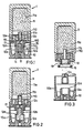
- FIGS. 4 to 7 shows a longitudinal section through an exercise cartridge
- FIG. 5 shows a side view of the cup 12 shown on an enlarged scale
- FIG. 6 - again enlarged - shows a section through the wall of the cup 12 in the region of the recesses 50
- FIG Side view of the cup 12 in a further embodiment.
- the advantageous developments of the invention differ from the exemplary embodiment according to FIGS. 1 to 3 mainly in that recesses 50 are arranged in the wall of the cup 12, which connect the space of the propellant charge 14 to the interior 10a of the sleeve 10.
- These recesses 50 are preferably arranged evenly distributed on a circumference, in the exemplary embodiment according to FIGS.
- four recesses 50 are provided with a mutual distance of 90 °. Through the recesses 50 it is achieved that, after igniting the propellant charge 14, the interior 10a of the sleeve 10 is also acted upon from the beginning with a gas pressure, albeit a lower one. In view of the large volume difference between the propellant charge space inside the cup 12 and the interior 10a of the sleeve 10, a lower pressure value is found in the interior 10a, which corresponds, for example, to only 1/10 of the pressure inside the cup 12.
- the predetermined breaking point 12d is dimensioned in such a way that it would not be destructible merely because of the propellant pressure generated in the interior of the cup 12.
- the predetermined breaking point 12d is designed in such a way that it would only be destroyed under a load of 750 kp.
- an internal pressure of approximately 400 bar inside the cup 12a and an area of approximately 1.25 cm 2 would only develop a force of approximately 500 kg. It is only through the interaction of the forces which act on the projectile 11 due to the pressure inside the cup 12a and in the interior 10a of the sleeve 10 that the predetermined breaking point 12d and the accelerator become destroyed inclination of the floor 11 allows.
- a pressure of about 50 bar contributes to this, which additionally exerts a force of 500 kp on a floor area of about 10 cm 2 .
- First the sum of the aforementioned force components . ten thus exceeds the crack resistance of the predetermined breaking point 12d.
- the outer diameter of the sleeve 10 was approximately 38 mm
- the inner diameter of the cup 12 was approximately 12 to 13 mm.
- four recesses 50 with a maximum diameter of approximately 2 mm were arranged at 90 ° intervals.
- the weight of the bullet was about 180 g.
- a weight of the propellant charge 14 of approximately 0.35 g
- a pressure of approximately 500 bar built up inside the cup 12 while approximately 1/10 of this pressure value, ie 50 bar, was determined in the interior 10a of the sleeve 10.
- a very uniform initial speed of the projectile 11 and a constant range with a very low standard deviation were achieved, so that all requirements of the user could be met.
- the range was constantly less than about 25 cm per 100 m compared to about 45 cm per 100 m for conventional ammunition.
- the standard deviation of the initial speed V o was always less than 1 m sec-1. This meant that the values demanded by the consumer could be met without difficulty.
- a membrane 50a which is not designed to be pressure-resistant, but immediately after the ignition Propellant charge 14 is destroyed.
- This membrane 50a can be made, for example, from a thin plastic or metal foil.
- the recesses 50 are expediently arranged lying within the ring-shaped predetermined breaking point 12d (FIG. 7).
- This embodiment has the advantage that no separate covering of the recesses 50, as shown in FIG. 6, is required, but that a reliable sealing of the recesses 50 is simultaneously effected by the O-ring, which seals the threaded connection between the sleeve 17 and the cup 12 is inserted into the predetermined breaking point 12d.
Description
- Die Erfindung betrifft eine patronierte Munition nach dem Oberbegriff des Patentanspruchs 1.
- Eine patronierte Munition für eine Granatpistole ist aus der DE-A-3 149 430 bekannt. Die bekannte Munition verfügt über eine aus Metall, beispielsweise aus Aluminium bestehende Kartusche oder Hülse, mit der der Granatkörper oder das Geschoß verbördelt ist. Zündladung und Treibladung sind in einer becherförmigen Treibladungspatrone angeordnet, die in den Boden der Hülse eingeschraubt ist. Radial verlaufend angeordnete Austrittsöffnungen ermöglichen nach Anzündung der Treibladung ein Ausbreiten der Treibladungsgase in den Hülseninnenraum und eine Beaufschlagung des Geschoßhecks mit Treibladungsdruck.
- Zum Zwecke der Kosteneinsparung wird bei patronierter Übungsmunition die Hülse vorzugsweise aus Kunststoff hergestellt und muß, da ein Verbördeln nicht möglich ist, mit dem in der Regel aus Metall bestehenden Geschoßkörper durch eine Klebverbindung verbunden werden.
- Klebverbindungen haben jedoch den Nachteil, daß trotz sorgfältiger Abstimmung und Überwachung aller Herstellungsparameter, auch innerhalb ein und desselben Loses, unterschiedlich starke Auszugskräfte beobachtet werden, die auch noch temperatur- und alterungsabhängig sind. Da bei Übungsmunition weiter im Vergleich zu Kampfmunition eine wesentlich geringere Treibladung verwendet wird, ergibt sich bei Austritt der Treibladungsgase aus der Treibladungspatrone oder dem Treibladungsbecher in den großvolumigen Innenraum der Treibladungshülse eine besonders nachteilige Temperaturabhängigkeit des Treibladungsgasdrucks. Beide Effekte führen in nachteiliger Weise dazu, daß sich stark voneinander abweichende Werte der Anfangsgeschwindigkeit des Geschosses (Vo) einstellen und reproduzierbare Schußergebnisse kaum zu erzielen sind. Bei bekannten Geschossen wurde weiter festgestellt, daß durch die in Radialrichtung in den Innenraum der Hülse austretenden Treibladungsgase der im Heckteil des Geschosses angeordnete Leuchtspur- oder Verzögerungssatz nicht mit hinreichender Zuverlässigkeit gezündet wird.
- Aus der FR-A-1 566 410 ist ferner eine Leuchtpatrone bekannt, bei der im wesentlichen die Merkmale des Oberbegriffs des Anspruchs 1 verwirklicht sind. Dabei sind das die Nutzlast enthaltende Geschoß und die Patronenhülse über umfangsseitig angeordnete Scherstifte miteinander verbunden. Würde man diese Anordnung auf Granatpatronen übertragen, wäre besonders nachteilig, daß die Schußergebnisse nicht ausreichend reproduzierbar sind, weil ein Abscheren der Stifte nicht exakt zeitgleich erfolgt.
- Der Erfindung liegt die Aufgabe zugrunde, patronierte Munition für eine Granatpistole dahingehend zu verbessern, daß die vorstehend beschriebenen Nachteile vermieden werden und vornehmlich durch eine konstante, nahezu temperaturunabhängige Anfangsgeschwindigkeit in einem weiteren Temperaturbereich reproduzierbare Schußergebnisse und eine sichere Anzündung des Leuchtspur- und/oder Verzögerungssatzes erzielt werden.
- Ausgehend von einer patronierten Munition der eingangs näher bezeichneten Art, wird diese Aufgabe durch die im kennzeichnenden Teil des Patentanspruchs 1 angegebenen Merkmale gelöst.
- Vorteilhafte Ausgestaltungen und Weiterbildungen der Erfindung gehen aus den Unteransprüchen hervor.
- Die Erfindung wird nachfolgend unter Bezug auf die Zeichnung näher erläutert. Dabei zeigt:
- Fig. 1 die Munition im Ruhezustand;
- Fig. 2 die Munition kurze Zeit nach Zündung der Treibladung;
- Fig. 3 die Munition nach Abtrennung des Geschosses von der Hülse;
- Fig. 4 bis 7 Weiterbildungen der Erfindung.
- Fig. 1 zeigt einen Längsschnitt durch eine patronierte Munition für eine Granatpistole, beispielsweise im Kaliber 40 mm. Die Munition 1 umfaßt eine aus z.B. Kunststoff bestehende Hülse 10, in deren Öffnung ein Geschoß 11 angeordnet ist, das beispielsweise eine Nebelladung 11 a und einen im Heckteil des Geschosses 11 angeordneten Leuchtspur- und/ oder Verzögerungssatz 11 b trägt. In einem im Boden der Hülse 10 angeordneten Becher 12 sind in einem im Vergleich zum Innenraum 10a der Hülse 10 geringeren Volumen eine Zündladung 13 und eine Treibladung 14 untergebracht. Der die Zünd- und Treibladung 13, 14 aufnehmende Becher 12 besteht aus zwei konzentrisch zueinander angeordneten Hülsen 12a, 12b. Die innerhalb liegende Hülse 12b ist topfförmig ausgebildet und in der äußeren Hülse 12a gleitbar und teleskopartig ausschiebbar gelagert. Die innenliegende topfförmig ausgebildete Hülse 12b trägt in ihrem Boden 12e einen auf den Leuchtspur-und/oder Verzögerungssatz 11 b im Heckteil des Geschosses 11 weisenden Zündkanal 12c.
- Die außenliegende Hülse 12a verfügt an ihrem freien Endstück, das in den Innenraum 1 Oa der Hülse 10 hineinragt, über ein Außengewinde 100 mit einer sich daran anschließenden ringförmig umlaufenden Sollbruchstelle 12d. Der Boden des Geschosses 11 verfügt über eine mit Innengewinde versehene Hülse 17, die auf die äußere Hülse 12a des Bechers 12 aufschraubbar ausgebildet ist.
- Durch die vorbeschriebene Konstruktion wird eine besonders einfache und kostengünstige Montage der Munition erreicht. Nach Einsetzen des die Zündladung 13 und die Treibladung 14 enthaltenden Bechers 12 in den Boden der Hülse 10 wird zunächst ein O-Ring 15 in die ringförmig umlaufende Sollbruchstelle 12d im Außenmantel der äußeren Hülse 12a des Bechers 12 eingelegt. Anschließend wird das Geschoß 11 vermittels der Hülse 17 auf das Außengewinde 100 des Bechers 12 aufgeschraubt, bis Hülse 10 und Geschoß 11 bündig aufeinander aufsitzen. Es erfolgt also kein Verkleben der aus Kunststoff bestehenden Hülse 10 mit dem Geschoß 11, so daß alle mit Klebverbindungen einhergehenden Nachteile, die eingangs beschrieben worden sind, vermieden werden. Bei Verwendung einer Metallhülse erübrigt sich so das Bördeln. Der in die Sollbruchstelle 12d eingelegte O-Ring 15 dichtet die Schraubverbindung zuverlässig gegen gegebenenfalls noch in den Innenraum 10a der Hülse 10 eintretende Feuchtigkeit ab, so daß die patronierte Munition auch bei sehr langer Lagerdauer betriebssicher funktionsfähig bleibt. Die Funktionsweise der Munition wird anhand der weiteren Fig. 2 und Fig. 4 erläutert. Nach Anzünden der Treibladung 14 über die Zündladung 13 baut sich im Treibladungsraum innerhalb des Bechers 12 ein Gasdruck auf, der jedoch erst beim Erreichen eines mit guter Reproduzierbarkeit vorherbestimmbaren Druckniveaus zum Nachgeben der ringförmigen, auf Zug belasteten Sollbruchstelle 12d führt.
- Nach Zerreißen der Sollbruchstelle 12d sorgt der Treibladungsdruck für eine Beschleunigung des Geschosses 11 und beginnt dieses aus der Treibladungshülse 10 hinauszudrücken. Das dabei für die Treibladungsgase zur Verfügung stehende Volumen wird jedoch nur vergleichsweise geringfügig vergrößert, da die in der äußeren Hülse 12a des Bechers 12 gleitbar und teleskopartig ausschiebbar gelagerte, topfförmig ausgebildete innere Hülse 12b durch Teilnahme an der Geschoßbewegung teleskopartig aus der äußeren Hülse 12a herausgedrückt wird, dabei jedoch durch Begrenzung des Treibladungsvolumens ein Austreten von Treibladungsgasen in den Innenraum 1 Oa der Hülse 10 verhindert. Erst nachdem - wie in Fig. 3 dargestellt - das Geschoß 11 seinen Freiflug im Patronenlager beendet hat und schon in die Züge des nicht dargestellten Waffenrohrs eingetreten ist und praktisch seine Endgeschwindigkeit erreicht hat, gibt die dann völlig von der äußeren Hülse 12a abgetrennte innere Hülse 12b den Weg für die Treibladungsgase frei, die dann auch in den Innenraum 1 Oa der Hülse 10 eintreten können. Wegen des sehr eng begrenzten kleinen Volumens, in dem sich die Treibladungsgase zunächst ausbreiten können, ergibt sich somit auf vorteilhafte Weise eine stark verringerte Temperaturabhängigkeit des Treibladungsgasdrucks, was wiederum trotz stark unterschiedlicher Umgebungstemperaturen zu einer konstanten Anfangsgeschwindigkeit des Geschosses 11 und damit zu reproduzierbaren Schußergebnissen führt.
- Die Beschränkung des Treibladungsvolumens auf ein zunächst kleineres Volumen ist an sich auch schon aus der DE-A-2 262 981 bekannt.
- Allerdings ist dort in nachteiliger Weise ein duktiler, den Treibladungsraum begrenzender Becher vorgesehen, der sich unter der Einwirkung der Treibladungsgase unter Aufbringung von Verformungsarbeit aufbauchen muß.
- Die topfförmig ausgebildete innere Hülse 12b des Bechers 12 verfügt in ihrem Boden 12e über einen Zündkanai 12c, der auf den im Heckteil des Geschosses 11 angeordneten Leuchtspur- und/oder Verzögerungssatz 11 b ausgerichtet ist. Unmittelbar nach Anzünden der Treibladung 14 können daher durch diesen Zündkanal 12c heiße Treibladungsgase hindurchtreten, wodurch - anders als bei herkömmlicher Munition - eine völlig zuverlässige Anzündung des Leuchtspur- und/oder Verzögerungssatzes 11 b ermöglicht wird.
- Der Leuchtspur- und/oder Verzögerungssatz 11 b dient gleichzeitig zur gegebenenfalls zeitverzögerten Anzündung einer im Geschoß 11 transportierten Nutzladung, hier beispielsweise einer Nebelladung 11 a. Dazu ist die den Leuchtspur- und/oder Verzögerungssatz 11 b aufnehmende Hülse 100 pyrotechnisch mit der Nebelladung 11 b in der Weise gekoppelt, daß gegen Ende des Ausbrennens des Leuchtspur- und/oder Verzögerungssatzes 11 b auch die Nebelladung 11 a angezündet wird. Im Geschoß 11 a baut sich daraufhin ein Druck auf, der nach Absprengen eines O-Rings 16, wie in Fig. 3 dargestellt, Nebelschwaden 19 durch vorzugsweise auf einem Kreisumfang gleichmäßig verteilt angeordnete Bohrungen 18 austreten läßt. Auf diese Weise tritt eine effektive Nebelwirkung schon in der letzten Flugphase des Geschosses auf, noch bevor dieses auf den Boden aufprallt. Anstelle einer Nebelladung kann im Geschoß 11 selbstverständlich auch eine andere Nutzladung, wie beispielsweise eine Blitz-, Knall-, Farb- und/oder Rauchladung, angeordnet sein.
- Vorteilhafte Weiterbildungen der Erfindung werden anhand von Fig. 4 bis Fig. 7 erläutert. Dabei zeigt: Fig. 4 einen Längsschnitt durch eine Übungspatrone, Fig. 5 eine Seitenansicht des in vergrößertem Maßstab dargestellten Bechers 12, Fig. 6 - nochmals vergrößert - einen Schnitt durch die Wandung des Bechers 12 im Bereich der Ausnehmungen 50 und Fig. 7 die Seitenansicht des Bechers 12 bei einem weiteren Ausführungsbeispiel. Die vorteilhaften Weiterbildungen der Erfindung unterscheiden sich vom Ausführungsbeispiel gemäß Fig. 1 bis Fig. 3 hauptsächlich dadurch, daß in der Wandung des Bechers 12 Ausnehmungen 50 angeordnet sind, die den Raum der Treibladung 14 mit dem Innenraum 10a der Hülse 10 verbinden. Diese Ausnehmungen 50 sind vorzugsweise gleichmäßig verteilt auf einem Kreisumfang liegend angeordnet, und zwar im Ausführungsbeispiel nach Fig. 5 bis Fig. 6 unterhalb der Sollbruchstelle 12d liegend. In einem Ausführungsbeispiel der Erfindung sind vier Ausnehmungen 50 vorgesehen mit einem gegenseitigen Abstand von 90°. Durch die Ausnehmungen 50 wird erreicht, daß nach Anzünden der Treibladung 14 auch der Innenraum 10a der Hülse 10 von Anfang an mit einem wenn auch geringeren Gasdruck beaufschlagt wird. Im Hinblick auf den großen Volumenunterschied zwischen dem Treibladungsraum innerhalb des Bechers 12 und dem Innenraum 10a der Hülse 10 ist im Innenraum 1 Oa ein geringerer Druckwert anzutreffen, der beispielsweise nur 1/10 des Drucks im Innern des Bechers 12 entspricht. Da jedoch das Geschoß 11 den Innenraum 10a der Hülse 10 mit einer relativ großen Fläche begrenzt, wird trotz des relativ niedrigen Gasdrucks im Innenraum 10a eine große Kraft auf das Geschoß 11 ausgeübt, die zur Trennung zwischen Geschoß 11 und Hülse 10 beiträgt. Bei dieser Weiterbildung der Erfindung ist die Sollbruchstelle 12d derart bemessen, daß sie lediglich aufgrund des im Innern des Bechers 12 entstehenden Treibladungsdrucks nicht zerstörbar wäre.
- Beispielsweise ist die Sollbruchstelle 12d so ausgelegt, daß sie erst bei einer Belastung von 750 kp zerstört würde. Durch einen Innendruck von etwa 400 bar im Innern des Bechers 12a und einer Fläche von ungefähr 1,25 cm2 würde aber nur eine Kraft von ungefähr 500 kg entwickelt. Erst durch das Zusammenwirken der Kräfte, die aufgrund des Drucks im Innern des Bechers 12a und im Innenraum 10a der Hülse 10 auf das Geschoß 11 einwirken, wird ein Zerstören der Sollbruchstelle 12d und die Beschleunigung des Geschosses 11 ermöglicht. Im Innenraum 10a der Hülse 10 trägt dazu ein Druck von etwa 50 bar bei, der auf eine Geschoßgrundfläche von ca. 10 cm2 eine Kraft von 500 kp zusätzlich ausübt. Erst die Summe der vorerwähnten Kraftkomponen- .ten übersteigt somit die Rißfestigkeit der Sollbruchstelle 12d.
- Dadurch, daß der Innenraum 10a durch die eingedrungenen Treibladungsgase schon vorgewärmt und mit einem gewissen Druckniveau beaufschlagt ist, läßt sich noch eine wesentlich größere Präzision hinsichtlich der Reproduzierbarkeit der Anfangsgeschwindigkeit des Geschosses 11 a und dessen Reichweite erzielen.
- In einem Ausführungsbeispiel der Erfindung betrug der Außendurchmesser der Hülse 10 etwa 38 mm, der Innendurchmesser des Bechers 12 etwa 12 bis 13 mm. Im Becher 12 waren mit jeweils 90° Abstand vier Ausnehmungen 50 mit einem maximalen Durchmesser von etwa 2 mm angeordnet. Das Gewicht des Geschosses betrug etwa 180 g. Mit einem Gewicht der Treibladung 14 von etwa 0,35 g baute sich im Innern des Bechers 12 ein Druck von etwa 500 bar auf, während im Innenraum 10a der Hülse 10 etwa 1/10 dieses Druckwertes, also 50 bar festgestellt wurde. Bei zahlreichen Testschüssen wurde eine sehr gleichmäßige Anfangsgeschwindigkeit des Geschosses 11 und eine konstant bleibende Reichweite mit sehr geringer Standardabweichung erzielt, so daß alle Forderungen des Bedarfsträgers erfüllt werden konnten. Die Reichweitenstreuung lag ständig unter etwa 25 cm pro 100 m im Vergleich zu etwa 45 cm pro 100 m bei herkömmlicher Munition. Die Standardabweichung der Anfangsgeschwindigkeit Vo lag stets unter 1 m sec-1. Damit konnten die vom Bedarfsträger geforderten Werte ohne Schwierigkeiten eingehalten werden.
- Um die Lagerfähigkeit der patronierten Munition zu verbessern und sie noch weniger anfällig gegen Feuchtigkeit zu machen, ist es zweckmäßig, die Ausnehmungen 50 - wie in Fig. 6 dargestellt - mit einer Membran 50a abzudecken, die nicht druckfest ausgebildet ist, sondern unmittelbar nach Anzünden der Treibladung 14 zerstört wird. Diese Membran 50a kann beispielsweise aus einer dünnen Kunststoff- oder Metallfolie hergestellt sein.
- In einem weiteren Ausführungsbeispiel der Erfindung werden die Ausnehmungen 50 zweckmäßig innerhalb der ringförmig ausgebildeten Sollbruchstelle 12d liegend angeordnet (Fig. 7). Dieses Ausführungsbeispiel bietet den Vorteil, daß keine gesonderte Abdeckung der Ausnehmungen 50, etwa nach Fig. 6, erforderlich ist, sondern daß eine zuverlässige Abdichtung der Ausnehmungen 50 gleichzeitig durch den O-Ring bewirkt wird, der zwecks Abdichtung der Gewindeverbindung zwischen der Hülse 17 und dem Becher 12 in die Sollbruchstelle 12d eingelegt ist.
Claims (10)
Priority Applications (1)
| Application Number | Priority Date | Filing Date | Title |
|---|---|---|---|
| AT86901398T ATE45035T1 (de) | 1985-03-05 | 1986-02-25 | Patronierte munition. |
Applications Claiming Priority (2)
| Application Number | Priority Date | Filing Date | Title |
|---|---|---|---|
| DE3507643 | 1985-03-05 | ||
| DE19853507643 DE3507643A1 (de) | 1985-03-05 | 1985-03-05 | Patronierte munition |
Publications (2)
| Publication Number | Publication Date |
|---|---|
| EP0215042A1 EP0215042A1 (de) | 1987-03-25 |
| EP0215042B1 true EP0215042B1 (de) | 1989-07-26 |
Family
ID=6264174
Family Applications (1)
| Application Number | Title | Priority Date | Filing Date |
|---|---|---|---|
| EP86901398A Expired EP0215042B1 (de) | 1985-03-05 | 1986-02-25 | Patronierte munition |
Country Status (16)
| Country | Link |
|---|---|
| US (3) | US4762068A (de) |
| EP (1) | EP0215042B1 (de) |
| KR (1) | KR920003085B1 (de) |
| AU (1) | AU589166B2 (de) |
| CA (1) | CA1286146C (de) |
| DE (2) | DE3507643A1 (de) |
| DK (1) | DK159944C (de) |
| ES (1) | ES8801429A1 (de) |
| FI (1) | FI864175A (de) |
| GR (1) | GR860345B (de) |
| IT (1) | IT1188562B (de) |
| NO (1) | NO161881C (de) |
| NZ (1) | NZ215357A (de) |
| SG (1) | SG79490G (de) |
| WO (1) | WO1986005265A1 (de) |
| ZA (1) | ZA861643B (de) |
Cited By (3)
| Publication number | Priority date | Publication date | Assignee | Title |
|---|---|---|---|---|
| DE19738937A1 (de) * | 1997-09-05 | 1999-03-18 | Nico Pyrotechnik | Patronierte Munition |
| DE19944486A1 (de) * | 1999-09-16 | 2001-04-19 | Nico Pyrotechnik | Irritationskörper |
| DE102004017464B4 (de) * | 2004-04-08 | 2006-05-18 | Nico-Pyrotechnik Hanns-Jürgen Diederichs GmbH & Co. KG | Patronierte Übungsmunition |
Families Citing this family (49)
| Publication number | Priority date | Publication date | Assignee | Title |
|---|---|---|---|---|
| DE3507643A1 (de) * | 1985-03-05 | 1986-09-11 | Nico-Pyrotechnik Hanns-Jürgen Diederichs GmbH & Co KG, 2077 Trittau | Patronierte munition |
| DE3827784A1 (de) * | 1988-08-16 | 1990-03-01 | Nico Pyrotechnik | Kontaktkopf fuer einen nebelwurfkoerper |
| DE3844955C2 (de) * | 1988-08-19 | 1999-04-15 | Nico Pyrotechnik | Wurfkörper, insbesondere Nebelwurfkörper |
| DE3918005A1 (de) * | 1988-09-22 | 1990-04-05 | Rheinmetall Gmbh | Granatengeschoss |
| DE8812000U1 (de) * | 1988-09-22 | 1990-02-08 | Rheinmetall Gmbh, 4000 Duesseldorf, De | |
| DE3840679A1 (de) * | 1988-12-02 | 1990-06-07 | Messerschmitt Boelkow Blohm | Abschusssystem |
| US5062366A (en) * | 1989-08-07 | 1991-11-05 | Honeywell Inc. | Temperature compensating control system for adjusting primary propellant chamber volume |
| DE59100386D1 (de) * | 1990-01-15 | 1993-10-21 | Udo Winter | Patrone, insbesondere granatpatrone. |
| DE4002722C2 (de) * | 1990-01-31 | 1994-02-17 | Diehl Gmbh & Co | Unterwasserwaffe |
| US5239928A (en) * | 1992-09-14 | 1993-08-31 | Vero Ricci | Reloadable slug assembly and method for making same |
| DE4328581A1 (de) * | 1993-08-25 | 1995-03-02 | Nico Pyrotechnik | Nebelwurfkörper |
| FR2717569B1 (fr) * | 1994-03-16 | 1996-05-10 | Giat Ind Sa | Dispositif d'allumage d'une charge propulsive. |
| NO180216B1 (no) * | 1994-11-11 | 1997-03-24 | Forsvarets Forsknings | Anordning ved roykgranat |
| DE19527621A1 (de) * | 1995-07-28 | 1997-01-30 | Nico Pyrotechnik | Patronierte Munition |
| US5791327A (en) * | 1997-01-18 | 1998-08-11 | Code-Eagle, Inc. | Personal protection device having a non-lethal projectile |
| FI108965B (fi) * | 1997-01-24 | 2002-04-30 | Patria Vammas Oy | Sovitelma kranaatin tukemiseksi takaaladattavan aseen putkeen |
| SE0001588D0 (sv) * | 2000-04-27 | 2000-04-27 | Comtri Ab | Granatpatron |
| KR20020073908A (ko) * | 2001-03-16 | 2002-09-28 | 박해식 | 폐자재를 이용한 폭탄 |
| NZ514921A (en) * | 2001-10-18 | 2002-12-20 | William James Sharplin | A grenade |
| FR2831256A1 (fr) * | 2001-10-22 | 2003-04-25 | Guy Cognet | Munition pour exercice de tir |
| AUPS182802A0 (en) * | 2002-04-19 | 2002-05-30 | Metal Storm Limited | Projectile sealing arrangement |
| US7004074B2 (en) * | 2002-07-01 | 2006-02-28 | Martin Electronics | Controlled fluid energy delivery burst cartridge |
| SE0302916D0 (sv) * | 2003-11-04 | 2003-11-04 | Comtri Teknik Ab | Utbytbar drivpatron |
| US7481167B2 (en) * | 2004-02-06 | 2009-01-27 | John Whitworth Engel | High-pressure fixed munition for low-pressure launching system |
| DE102004020838B3 (de) * | 2004-04-08 | 2005-06-23 | Nico-Pyrotechnik Hanns-Jürgen Diederichs GmbH & Co. KG | Patronenmunition, insbesondere mit mittlerem Kaliber |
| AU2005230669B2 (en) | 2004-04-08 | 2010-10-21 | Rheinmetall Waffe Munition Gmbh | Cartridged ammunition, especially of an average caliber |
| US7287475B2 (en) * | 2006-01-03 | 2007-10-30 | Combined Systems, Inc. | Reloadable non-lethal training cartridge |
| AU2007216864A1 (en) * | 2006-09-29 | 2008-04-17 | William James Sharplin | Ammunition |
| EP1914507A1 (de) * | 2006-10-19 | 2008-04-23 | Saab Ab | Anordnung für eine Granate |
| US8056481B2 (en) * | 2007-03-13 | 2011-11-15 | Dindl Frank J | Controlled deceleration projectile |
| US20080223246A1 (en) * | 2007-03-13 | 2008-09-18 | Dindl Frank J | Burping projectile |
| DE102007025981A1 (de) | 2007-06-04 | 2008-12-11 | Rheinmetall Waffe Munition Gmbh | Patronenmunition, insbesondere Übungsmunition |
| US7793591B1 (en) * | 2007-06-06 | 2010-09-14 | Martin Electronics | Projectile having ignitable payload with delay column igniter |
| FI20085083L (fi) * | 2008-01-31 | 2009-08-01 | Patria Weapon Systems Oy | Sovitelma ja menetelmä kranaatin tukemiseksi takaaladattavan aseen putkeen |
| AU2010328601A1 (en) | 2009-09-03 | 2012-02-09 | Kms Consulting Llc | Pressure-relief system for gun fired cannon cartridges |
| US8925463B1 (en) * | 2009-09-03 | 2015-01-06 | Kms Consulting, Llc | Pressure relief system for gun fired cannon cartridges |
| DE102009048365B3 (de) * | 2009-10-06 | 2010-10-07 | Rheinmetall Waffe Munition Gmbh | Patronierte Munition mit einer Berstvorrichtung als Verbindung zwischen Geschoss und Antrieb |
| JP5638996B2 (ja) * | 2011-03-30 | 2014-12-10 | 株式会社ダイセル | 人員拘束装置用ガス発生器 |
| KR101384214B1 (ko) * | 2012-04-04 | 2014-04-10 | 국방과학연구소 | 능동파괴체계의 대응탄의 급속 발사를 위한 개방형 추진장치 |
| DE102012014043B4 (de) | 2012-07-14 | 2014-02-13 | Diehl Bgt Defence Gmbh & Co. Kg | Granate, insbesondere 40-mm-Granate |
| US10132601B2 (en) * | 2013-03-15 | 2018-11-20 | William Joseph Nemec | Advanced modular ammunition cartridges and systems |
| LU92216A1 (fr) * | 2013-06-17 | 2014-12-18 | Securinov Sa | Douille régulée en pression de combustion pour petit et moyen calibre |
| US9557150B2 (en) * | 2013-06-20 | 2017-01-31 | Atlantis Manufacturing Management Services Proprietary Limited | Grenade round |
| FR3013114B1 (fr) * | 2013-11-13 | 2015-12-25 | Soc Darmement Et Detudes Alsetex | Dispositif de propulsion pour une munition utilisable avec un lanceur |
| DE202014105939U1 (de) | 2014-12-09 | 2015-01-26 | Kms Consulting Llc | Patronenhülse mit Druckauslass |
| JP6563773B2 (ja) * | 2015-10-20 | 2019-08-21 | 株式会社ダイセル | 煙幕発生器 |
| DE102016015042B4 (de) | 2016-12-16 | 2018-08-23 | Diehl Defence Gmbh & Co. Kg | Munitionsmodul, Gefechtskopf und Munition |
| DE102017110871A1 (de) * | 2017-05-18 | 2018-11-22 | Rheinmetall Waffe Munition Gmbh | Antriebssystem für Patronenmunition |
| DE102018001031A1 (de) * | 2018-02-08 | 2019-08-08 | Bundesrepublik Deutschland, vertr. durch das Bundesministerium der Verteidigung, vertr. durch das Bundesamt für Ausrüstung, Informationstechnik und Nutzung der Bundeswehr | Vorrichtung und Verfahren zur Bekämpfung von Kleindrohnen |
Family Cites Families (12)
| Publication number | Priority date | Publication date | Assignee | Title |
|---|---|---|---|---|
| US2592623A (en) * | 1948-02-16 | 1952-04-15 | Norman K Turnbull | Primer assembly for artillery ammunition |
| US2872864A (en) * | 1952-01-08 | 1959-02-10 | Gladeon M Barnes | Center-guide for fin-stabilized fixed round ammunition |
| US3547030A (en) * | 1954-01-27 | 1970-12-15 | Us Army | Rocket and cartridge case therefor |
| FR1566410A (de) * | 1968-02-23 | 1969-05-09 | ||
| US3609904A (en) * | 1969-05-07 | 1971-10-05 | Remington Arms Co Inc | Extractable plastic cartridge |
| US3776136A (en) * | 1971-12-30 | 1973-12-04 | Aai Corp | Ammunition arrangement |
| US3981241A (en) * | 1973-10-11 | 1976-09-21 | The United States Of America As Represented By The Secretary Of The Army | Self-levitating signal cartridge |
| US4197801A (en) * | 1978-04-07 | 1980-04-15 | Ford Aerospace & Communications Corporation | Ammunition round |
| CH627550A5 (de) * | 1978-05-30 | 1982-01-15 | Oerlikon Buehrle Ag | Drallstabilisiertes treibspiegelgeschoss zur ueberwindung eines heterogenen widerstandes. |
| AT371596B (de) * | 1980-12-23 | 1983-07-11 | Oregon Ets Patentverwertung | Granate |
| EP0131863B1 (de) * | 1983-07-15 | 1988-09-28 | Confederate Creek, Inc. | Patronenhülse aus Kunststoff |
| DE3507643A1 (de) * | 1985-03-05 | 1986-09-11 | Nico-Pyrotechnik Hanns-Jürgen Diederichs GmbH & Co KG, 2077 Trittau | Patronierte munition |
-
1985
- 1985-03-05 DE DE19853507643 patent/DE3507643A1/de not_active Withdrawn
-
1986
- 1986-02-05 GR GR860345A patent/GR860345B/el unknown
- 1986-02-25 EP EP86901398A patent/EP0215042B1/de not_active Expired
- 1986-02-25 WO PCT/EP1986/000097 patent/WO1986005265A1/de active IP Right Grant
- 1986-02-25 US US06/948,359 patent/US4762068A/en not_active Expired - Lifetime
- 1986-02-25 DE DE8686901398T patent/DE3664684D1/de not_active Expired
- 1986-02-25 AU AU55409/86A patent/AU589166B2/en not_active Ceased
- 1986-03-03 CA CA000503117A patent/CA1286146C/en not_active Expired - Lifetime
- 1986-03-04 NZ NZ215357A patent/NZ215357A/en unknown
- 1986-03-04 ES ES552635A patent/ES8801429A1/es not_active Expired
- 1986-03-05 IT IT19640/86A patent/IT1188562B/it active
- 1986-03-05 ZA ZA861643A patent/ZA861643B/xx unknown
- 1986-09-05 KR KR1019860007516A patent/KR920003085B1/ko not_active IP Right Cessation
- 1986-09-11 DK DK436086A patent/DK159944C/da not_active IP Right Cessation
- 1986-09-25 NO NO863813A patent/NO161881C/no unknown
- 1986-10-16 FI FI864175A patent/FI864175A/fi not_active Application Discontinuation
-
1988
- 1988-02-22 US US07/157,481 patent/US4815387A/en not_active Expired - Lifetime
- 1988-12-06 US US07/287,261 patent/US4892038A/en not_active Expired - Lifetime
-
1990
- 1990-09-29 SG SG794/90A patent/SG79490G/en unknown
Cited By (5)
| Publication number | Priority date | Publication date | Assignee | Title |
|---|---|---|---|---|
| DE19738937A1 (de) * | 1997-09-05 | 1999-03-18 | Nico Pyrotechnik | Patronierte Munition |
| DE19738937C2 (de) * | 1997-09-05 | 1999-07-29 | Nico Pyrotechnik | Patronierte Munition |
| DE19944486A1 (de) * | 1999-09-16 | 2001-04-19 | Nico Pyrotechnik | Irritationskörper |
| DE19944486C2 (de) * | 1999-09-16 | 2003-06-26 | Nico Pyrotechnik | Irritationskörper |
| DE102004017464B4 (de) * | 2004-04-08 | 2006-05-18 | Nico-Pyrotechnik Hanns-Jürgen Diederichs GmbH & Co. KG | Patronierte Übungsmunition |
Also Published As
| Publication number | Publication date |
|---|---|
| NO161881C (no) | 1989-10-04 |
| DK159944B (da) | 1990-12-31 |
| SG79490G (en) | 1991-08-23 |
| DK159944C (da) | 1991-05-21 |
| DK436086A (da) | 1986-10-23 |
| US4762068A (en) | 1988-08-09 |
| FI864175A0 (fi) | 1986-10-16 |
| EP0215042A1 (de) | 1987-03-25 |
| KR880004291A (ko) | 1988-06-03 |
| FI864175A (fi) | 1986-10-16 |
| ES8801429A1 (es) | 1988-01-16 |
| NO863813D0 (no) | 1986-09-25 |
| DE3664684D1 (de) | 1989-08-31 |
| IT8619640A1 (it) | 1987-09-05 |
| NZ215357A (en) | 1987-07-31 |
| NO161881B (no) | 1989-06-26 |
| GR860345B (en) | 1986-06-26 |
| ZA861643B (en) | 1986-11-26 |
| DK436086D0 (da) | 1986-09-11 |
| KR920003085B1 (ko) | 1992-04-13 |
| CA1286146C (en) | 1991-07-16 |
| AU589166B2 (en) | 1989-10-05 |
| US4892038A (en) | 1990-01-09 |
| US4815387A (en) | 1989-03-28 |
| ES552635A0 (es) | 1988-01-16 |
| AU5540986A (en) | 1986-09-24 |
| IT1188562B (it) | 1988-01-20 |
| NO863813L (no) | 1986-09-25 |
| WO1986005265A1 (en) | 1986-09-12 |
| DE3507643A1 (de) | 1986-09-11 |
| IT8619640A0 (it) | 1986-03-05 |
Similar Documents
| Publication | Publication Date | Title |
|---|---|---|
| EP0215042B1 (de) | Patronierte munition | |
| EP1735580A1 (de) | Patronierte übungsmunition | |
| EP1338860A2 (de) | Verfahren zur Herstellung eines grosskalibrigen Sprenggeschosses und Sprenggeschoss, hergestellt nach diesem Verfahren | |
| DE1951006A1 (de) | Patrone fuer Feuerwaffen | |
| DE2105295C1 (de) | Pulverkörper für hülsenlose Munition | |
| DE10065816B4 (de) | Munition zur Erzeugung eines Nebels | |
| DE2826497A1 (de) | Treibspiegelgeschoss mit pyrotechnischem satz | |
| EP0158121A2 (de) | Patronierte Munition für Rohrwaffen | |
| EP0656522B1 (de) | Patronenhülse | |
| DE3918005C2 (de) | ||
| DE3629371A1 (de) | Sprengzeitzuender | |
| EP0600385A1 (de) | Treibladungsanzünder | |
| DE4445990A1 (de) | Patrone mit einer Patronenhülse und einem Pfeilgeschoß | |
| DE3815738A1 (de) | Patrone mit flintenlaufgeschoss | |
| DE3048595A1 (de) | "gefechtskopf fuer tarn- und/oder taeuschzwecke" | |
| DE3823628C2 (de) | ||
| US4221167A (en) | Delay burster for a projectile | |
| EP0327681A2 (de) | Sprenggeschoss | |
| WO1993018364A1 (de) | Verfahren und vorrichtung zum verschiessen von hülsenloser munition | |
| DE4016001A1 (de) | Uebungspatrone | |
| DE4336808C2 (de) | Prüfgeschoß zum Anzeigen der Zündfunktion eines Geschosses | |
| DE3149430A1 (de) | Granate | |
| DE102018115072A1 (de) | De- und aktivierbarer Base-Bleed | |
| CH693543A5 (de) | Patronierte Munition. | |
| DE2920135A1 (de) | Vorrichtung zur zuendung einer zuendschnur, eines verzoegerungssatzes oder einer sprengkapsel |
Legal Events
| Date | Code | Title | Description |
|---|---|---|---|
| PUAI | Public reference made under article 153(3) epc to a published international application that has entered the european phase |
Free format text: ORIGINAL CODE: 0009012 |
|
| 17P | Request for examination filed |
Effective date: 19861103 |
|
| AK | Designated contracting states |
Kind code of ref document: A1 Designated state(s): AT BE CH DE FR GB IT LI LU NL SE |
|
| 17Q | First examination report despatched |
Effective date: 19880504 |
|
| GRAA | (expected) grant |
Free format text: ORIGINAL CODE: 0009210 |
|
| AK | Designated contracting states |
Kind code of ref document: B1 Designated state(s): AT BE CH DE FR GB IT LI LU NL SE |
|
| PG25 | Lapsed in a contracting state [announced via postgrant information from national office to epo] |
Ref country code: IT Free format text: LAPSE BECAUSE OF FAILURE TO SUBMIT A TRANSLATION OF THE DESCRIPTION OR TO PAY THE FEE WITHIN THE PRESCRIBED TIME-LIMIT;WARNING: LAPSES OF ITALIAN PATENTS WITH EFFECTIVE DATE BEFORE 2007 MAY HAVE OCCURRED AT ANY TIME BEFORE 2007. THE CORRECT EFFECTIVE DATE MAY BE DIFFERENT FROM THE ONE RECORDED. Effective date: 19890726 |
|
| REF | Corresponds to: |
Ref document number: 45035 Country of ref document: AT Date of ref document: 19890815 Kind code of ref document: T |
|
| GBT | Gb: translation of ep patent filed (gb section 77(6)(a)/1977) | ||
| REF | Corresponds to: |
Ref document number: 3664684 Country of ref document: DE Date of ref document: 19890831 |
|
| ET | Fr: translation filed | ||
| PG25 | Lapsed in a contracting state [announced via postgrant information from national office to epo] |
Ref country code: LU Free format text: LAPSE BECAUSE OF NON-PAYMENT OF DUE FEES Effective date: 19900228 |
|
| PLBE | No opposition filed within time limit |
Free format text: ORIGINAL CODE: 0009261 |
|
| STAA | Information on the status of an ep patent application or granted ep patent |
Free format text: STATUS: NO OPPOSITION FILED WITHIN TIME LIMIT |
|
| 26N | No opposition filed | ||
| PGFP | Annual fee paid to national office [announced via postgrant information from national office to epo] |
Ref country code: BE Payment date: 19910122 Year of fee payment: 6 |
|
| PG25 | Lapsed in a contracting state [announced via postgrant information from national office to epo] |
Ref country code: BE Effective date: 19920228 |
|
| BERE | Be: lapsed |
Owner name: NICO-PYROTECHNIK HANNS-JURGEN DIEDERICHS G.M.B.H. Effective date: 19920228 |
|
| EAL | Se: european patent in force in sweden |
Ref document number: 86901398.7 |
|
| REG | Reference to a national code |
Ref country code: GB Ref legal event code: IF02 |
|
| PGFP | Annual fee paid to national office [announced via postgrant information from national office to epo] |
Ref country code: DE Payment date: 20050208 Year of fee payment: 20 |
|
| PGFP | Annual fee paid to national office [announced via postgrant information from national office to epo] |
Ref country code: SE Payment date: 20050210 Year of fee payment: 20 Ref country code: FR Payment date: 20050210 Year of fee payment: 20 Ref country code: CH Payment date: 20050210 Year of fee payment: 20 |
|
| PGFP | Annual fee paid to national office [announced via postgrant information from national office to epo] |
Ref country code: AT Payment date: 20050211 Year of fee payment: 20 Ref country code: NL Payment date: 20050211 Year of fee payment: 20 |
|
| PGFP | Annual fee paid to national office [announced via postgrant information from national office to epo] |
Ref country code: GB Payment date: 20050214 Year of fee payment: 20 |
|
| REG | Reference to a national code |
Ref country code: GB Ref legal event code: PE20 |
|
| PG25 | Lapsed in a contracting state [announced via postgrant information from national office to epo] |
Ref country code: GB Free format text: LAPSE BECAUSE OF EXPIRATION OF PROTECTION Effective date: 20060224 |
|
| PG25 | Lapsed in a contracting state [announced via postgrant information from national office to epo] |
Ref country code: NL Free format text: LAPSE BECAUSE OF EXPIRATION OF PROTECTION Effective date: 20060225 |
|
| REG | Reference to a national code |
Ref country code: CH Ref legal event code: PL |
|
| EUG | Se: european patent has lapsed | ||
| NLV7 | Nl: ceased due to reaching the maximum lifetime of a patent |
Effective date: 20060225 |