EP0205654B2 - Installation permettant de faire couler un film liquide de grande largeur sur une matière en bande - Google Patents
Installation permettant de faire couler un film liquide de grande largeur sur une matière en bande Download PDFInfo
- Publication number
- EP0205654B2 EP0205654B2 EP85112348A EP85112348A EP0205654B2 EP 0205654 B2 EP0205654 B2 EP 0205654B2 EP 85112348 A EP85112348 A EP 85112348A EP 85112348 A EP85112348 A EP 85112348A EP 0205654 B2 EP0205654 B2 EP 0205654B2
- Authority
- EP
- European Patent Office
- Prior art keywords
- fluid
- liquid
- working width
- overflow weir
- inlet gap
- Prior art date
- Legal status (The legal status is an assumption and is not a legal conclusion. Google has not performed a legal analysis and makes no representation as to the accuracy of the status listed.)
- Expired - Lifetime
Links
Images

Classifications
-
- B—PERFORMING OPERATIONS; TRANSPORTING
- B05—SPRAYING OR ATOMISING IN GENERAL; APPLYING FLUENT MATERIALS TO SURFACES, IN GENERAL
- B05C—APPARATUS FOR APPLYING FLUENT MATERIALS TO SURFACES, IN GENERAL
- B05C5/00—Apparatus in which liquid or other fluent material is projected, poured or allowed to flow on to the surface of the work
- B05C5/007—Slide-hopper coaters, i.e. apparatus in which the liquid or other fluent material flows freely on an inclined surface before contacting the work
-
- D—TEXTILES; PAPER
- D06—TREATMENT OF TEXTILES OR THE LIKE; LAUNDERING; FLEXIBLE MATERIALS NOT OTHERWISE PROVIDED FOR
- D06B—TREATING TEXTILE MATERIALS USING LIQUIDS, GASES OR VAPOURS
- D06B1/00—Applying liquids, gases or vapours onto textile materials to effect treatment, e.g. washing, dyeing, bleaching, sizing or impregnating
- D06B1/04—Applying liquids, gases or vapours onto textile materials to effect treatment, e.g. washing, dyeing, bleaching, sizing or impregnating by pouring or allowing to flow on to the surface of the textile material
- D06B1/06—Applying liquids, gases or vapours onto textile materials to effect treatment, e.g. washing, dyeing, bleaching, sizing or impregnating by pouring or allowing to flow on to the surface of the textile material flowing along an inclined surface
-
- Y—GENERAL TAGGING OF NEW TECHNOLOGICAL DEVELOPMENTS; GENERAL TAGGING OF CROSS-SECTIONAL TECHNOLOGIES SPANNING OVER SEVERAL SECTIONS OF THE IPC; TECHNICAL SUBJECTS COVERED BY FORMER USPC CROSS-REFERENCE ART COLLECTIONS [XRACs] AND DIGESTS
- Y10—TECHNICAL SUBJECTS COVERED BY FORMER USPC
- Y10S—TECHNICAL SUBJECTS COVERED BY FORMER USPC CROSS-REFERENCE ART COLLECTIONS [XRACs] AND DIGESTS
- Y10S118/00—Coating apparatus
- Y10S118/04—Curtain coater
Definitions
- the invention relates to a device for applying a uniformly thin, laminar flowing liquid film of large width over the working width to a continuously advanced web with a liquid storage space, which is fed on the one hand by a pump via a liquid inflow hose and on the other hand is directed obliquely upwards and horizontally has over the working width extending baffle wall, which is followed by an overflow weir in the direction of flow of the liquid film and a guide surface adjoining the overflow weir, from the lower edge of which the overflowing liquid film runs onto the material web.
- a device of this type is known from FR-A-2 024 915.
- the liquid storage space located upstream of the overflow weir not only has a large volume of approximately 200 l / m and more, but also contains a plurality of complex stowage devices or liquid sedative elements wetted by the liquid, which are necessary for the formation of a liquid film flowing over the guide surface in a laminar manner are.
- application quantities of 30-100 l / min / m are common. As a result, a strong flow of liquid must flow continuously into the liquid storage space.
- the order systems working according to the overflow principle still include those according to US-A-4 041 897.
- This is a cascade application device for coating films, to which several coating compositions arranged one above the other are to be applied.
- several vertically aligned slots are arranged one behind the other in the direction of flow across the working width and open at the top into an overflow weir running obliquely downwards.
- the overflow edge of the respective slot is rounded or slightly chamfered, so that the slot is enlarged in the direction of flow.
- the slots open into a distribution pipe, which also extends over the working width, into which in turn feed lines for the liquid to be applied open from below.
- a faster change of colors is possible with the help of the device according to DE-A-3 127 469, according to which an order bar is assigned to the web over the working width, which is provided with chambers open to the web, each with a hose connection with an under Pressurized liquid storage tank are connected. Then only a small volume of fluid medium is supplied to the respective chamber via the large number of hose connections, so that the colors can now be changed quickly without Production loss is possible.
- the disadvantage is the unavoidable streaking in the dyeing result, which is due to a non-uniform distribution of the dyeing liquid over the working width and to the large number of hose connections.
- the object of the invention is to change it in such a way that a rapid change of application liquid is possible without the associated loss of production of the web to be wetted, at the same time, however, an exact, even distribution of the application liquid over the working width is guaranteed.
- the invention provides that the liquid storage space is formed between the baffle wall and a diffuser wall, which is arranged steeper than the baffle wall to form a storage space that widens conically towards the overflow weir, and the diffuser wall together with the baffle wall form at the end opposite the overflow weir a liquid inlet gap which extends across the working width and is narrow in cross section and which is preceded by a liquid distribution chamber with the liquid inflow hose which is smaller in cross section than the storage space.
- the arrangement of a liquid distribution space with inlet pipe and outlet slot is known per se from US-A-4 041 897.
- liquid storage space adjoining the inlet slot which is larger in cross section due to its longitudinal extension than the distribution space and slowly widens conically over this length.
- the calming of the liquid feed stream up to the overflow weir necessary for the formation of a laminar liquid film is achieved.
- the slowly increasing volume increases the vortex equalization up to the overflow weir.
- liquid volume in the storage space is consequently considerably smaller than, for example, in the device according to FR-A-2 024 915 or GB-A-2 147 527.
- the amount of liquid flowing in at high speed of the device slows down from the narrow liquid inlet gap to the level at the overflow weir. It has been found that, despite a small volume in the liquid storage space, the production of the desired uniform liquid film can be influenced by a variety of measures. So it is e.g. advantageous if the liquid inlet gap with a constant cross section over a longer length of e.g. Extends 25 mm.
- displacement bodies e.g. displacers widening conically towards the overflow weir.
- Such displacement bodies can, however, also be arranged in front of or behind the liquid inlet gap.
- a threaded rod or the like should be mentioned, which is arranged in the region of the liquid inlet gap on the side of the storage space.
- the liquid distribution space which - as is known - is formed along the working width with a constant cross section, is according to the Invention formed in cross section smaller than the liquid storage space. This also means that only little liquid is present in the overall system of the application device, so that a quick color change with little loss of liquid is made possible.
- the fluid flows through holes, of which only z. B. two are distributed over the meter of the working width, with high inflow speed. It is expedient to influence the distribution of the liquid over the working width from the liquid distribution space to the liquid inlet gap by means of an additional throttling point, which is achieved via a sieve plate. whose flow openings should be arranged away from the liquid inlet gap.
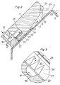
- the liquid application device consists of an angular support 1, the 90 ° corner of which is oriented upwards.
- One leg of the angle bracket is the baffle wall 2, which is oriented obliquely upwards in the direction of the overflow weir 3.
- the overflow weir 3 is followed by the guide surface 4, through which the uniformly distributed liquid film runs down and flows onto the web 5 that runs underneath.
- the web 5 is carried with the pile arranged upwards over a deflection roller 6.
- a solid body 7 is arranged on the side opposite the baffle wall 2, the wall of which is associated with the baffle wall 2 is designated as the diffuser wall 8.
- the body 7 extends over e.g.
- a branching device 11 is provided, in which the uniform division into two partial flows of the incoming liquid in the direction of arrow 12 is ensured.
- Upstream of the liquid branching device 11 are two optionally switchable storage containers 13, 14, which are connected to the branching device 11 via a three-way valve 15 with flow measuring devices etc.
- the liquid application device shown in FIG. 1 can be seen in detail in FIG.
- the liquid distributed by the branching device 11 in two partial flows flows z. B. via the hose 9 into the bore 17 and from there into the semicircular opening 18, the open side of which is directly assigned to the liquid distribution space 19. While only two of the semicircular openings 18 are provided over the working width of 1 m, the liquid distribution space 19 extends uniformly over the working width.
- the liquid storage space 20 From the end of the liquid inlet gap 21, the liquid storage space 20 begins.
- This storage space is formed by the baffle wall 2 and by the diffuser wall 8, which is arranged approximately 10 ° steeper than the baffle wall 2 to form the storage space 20 which widens conically towards the overflow weir 3.
- the end 23 of the diffuser wall 8 assigned to the overflow weir 3 can be erected even steeper in front of the liquid level 24.
- the liquid can also be made more uniform by a liquid-permeable curtain 30 which extends from the diffuser wall 8 to the baffle wall 2.
- a baffle 25 should expediently be arranged in the liquid distribution space 19, which has a row of flow openings 26 along the working width in the rear end of the liquid distribution space 19, the flow cross section from the liquid distribution space 19 to these flow openings 26 being approximately 1/5 to 1 / 10 limited. From there, the liquid flows back again to the connecting gap 22 and finally to the liquid inlet gap 21, whereby the liquid flows around a nose 27 which extends towards the connecting gap 22.
- Displacement bodies 28 can be arranged in the liquid inlet gap 21, which can be seen in FIG. 3.
- the displacement bodies 28 shown are triangular in shape, arranged closely next to one another and thus leave a flow space 31 which widens conically towards the overflow weir 3. A further calming of the liquid flow is possible by, for example, in the region of the end of the liquid inlet gap 21.
- B. a threaded rod 29 is placed in the storage space 20.
Landscapes
- Engineering & Computer Science (AREA)
- Textile Engineering (AREA)
- Coating Apparatus (AREA)
- Treatment Of Fiber Materials (AREA)
Claims (18)
- Dispositif destiné au dépôt d'une mince pellicule de liquide de grande largeur qui se répand de façon uniforme et régulière, par écoulement laminaire, sur une nappe ou sur une bande de produit textile, sur toute la largeur de traitement de cette nappe ou de cette bande de produit textile (5), qui est déplacée de telle manière qu'elle avance de façon continue, dispositif de dépôt qui comporte une chambre d'approvisionnement recevant le liquide de traitement (20) qui d'une part est alimentée à l'intervention d'une pompe par des tuyaux flexibles d'arrivée de liquide de traitement (9,10) et qui d'autre part présente une paroi de refoulement (2) dirigée en oblique vers le haut et s'étendant sur toute la largeur de traitement de cette nappe ou de cette bande de produit textile, chambre d'approvisionnement dont la paroi de refoulement rejoint le trop-plein de déversement (3) en direction de l'écoulement de la pellicule de liquide ainsi que l'aile directrice d'écoulement (4) qui y fait immédiatement suite, aile directrice de l'écoulement du bord inférieur de laquelle la pellicule de liquide de traitement, qui déborde du trop-plein de déversement, s'écoule sur la nappe ou sur la bande de produit textile (5), le dispositif de dépôt étant caractérisé en ce que la chambre d'approvisionnement (20) est délimitée par la paroi de refoulement (2) et par la paroi de diffusion (8), laquelle, pour la formation de la chambre d'approvisionnement (20), qui va en s'élargissant en forme de tronc de cône en direction du trop-plein de déversement (3), est prévue de telle façon qu'elle suive une pente plus raide d'environ 10° par rapport à la pente qui suit la paroi de refoulement (2), en ce que la paroi de diffusion (8) et la paroi de refoulement (2) laissent subsister entre elles, en leurs parties d'extrémité qui se trouvent en opposition au trop-plein de déversement (3), un intervalle sous forme de fente (21) destiné à permettre l'arrivée du liquide de traitement, intervalle de passage du liquide qui est de section transversale étroite et qui s'étend sur toute la largeur de traitement de la nappe ou de la bande de produit textile , et en ce qu'il est muni d'une chambre de répartition de liquide de traitement (19) qui se trouve à l'avant de l'intervalle sous forme de fente (21) destiné à permettre l'arrivée du liquide de traitement et qui s'étend suivant le sens longitudinal de la largeur de traitement de la nappe ou de la bande de produit textile, la chambre précitée (19) de répartition du liquide étant prévue de telle sorte que sa section transversale soit plus faible que la section transversale de la chambre d'approvisionnement (20) recevant le liquide de traitement et étant traversée par les tuyaux flexibles d'arrivée du liquide de traitement.
- Dispositif suivant la revendication 1, caractérisé en ce que la capacité de la chambre d'approvisionnement (20) recevant le liquide de traitement est, même pour une quantité ou débit de liquide de dépôt de plus de 30 l/min/m, inférieure à 5 l/m et est de préférence inférieure à 2,5 l/m.
- Dispositif suivant la revendication 1, caractérisé en ce que la partie d'extrémité (23) de la paroi de diffusion (8) qui correspond au trop-plein de déversement (3), pour coopérer avec celui-ci, partie d'extrémité (23) qui se situe en face du niveau (24) du liquide de traitement, suit une direction en pente plus raide encore que la partie de cette paroi de diffusion (8) qui se trouve en amont de cette partie d'extrémité (23).
- Dispositif suivant la revendication 1 et/ou suivant la revendication 3, caractérisé en ce qu'il est prévu dans la chambre d'approvisionnement (20) recevant le liquide de traitement, dans le sens transversal de cette chambre d'approvisionnement (20), un rideau permettant le passage du liquide, rideau qui est prévu par exemple sous la forme d'une toile de tamisage (30) ou d'un autre élément du même genre, ce rideau allant de la paroi de diffusion (8) jusqu'à la paroi de refoulement (2) et s'étendant sur toute la largeur de traitement de la nappe ou de la bande de produit textile.
- Dispositif suivant la revendication 1, caractérisé en ce que l'intervalle sous forme de fente (21) destiné à permettre l'arrivée du liquide de traitement se présente en une dimension de section transversale qui est inférieure à 5 mm et qui est de préférence de 2 mm.
- Dispositif suivant l'une ou l'autre des revendications 1 et 5, caractérisé en ce que l'intervalle sous forme de fente (21) destiné à permettre l'arrivée du liquide de traitement se présente en une longueur qui est relativement grande par rapport à la faible dimension de sa section transversale, longueur qui est de l'ordre de 20 à 35 mm et qui est de préférence prévue de 25 mm.
- Dispositif suivant l'une ou l'autre des revendications 1 et 6, caractérisé en ce qu'il est muni, dans l'intervalle sous forme de fente (21) destiné à permettre l'arrivée du liquide de traitement ou dans la zone de cet intervalle sous forme de fente (21), d'un ou de plusieurs éléments de refoulement (28 et 29) qui sont prévus de telle sorte qu'ils ferment en partie la section transversale d'écoulement du liquide de traitement de cet intervalle sous forme de fente (21).
- Dispositif suivant la revendication 7, caractérisé en ce que la section transversale d'écoulement du liquide de traitement qui est laissée ouverte au passage de ce liquide par les éléments de refoulement (28) est prévue de telle sorte qu'elle aille en s'élargissant en forme de tronc de cône en direction du trop-plein de déversement (3).
- Dispositif suivant la revendication 8, caractérisé en ce que les éléments de refoulement (28) se présentent sous une forme triangulaire et en ce qu'ils sont prévus l'un à côté de l'autre de façon à être étroitement rapprochés l'un de l'autre.
- Dispositif suivant la revendication 7, caractérisé en ce que l'élément de refoulement se présente sous la forme d'une ligne hélicoïdale.
- Dispositif suivant la revendication 1, caractérisé en ce qu'il comporte, allant de la chambre précitée (19) de répartition du liquide de traitement à l'intervalle sous forme de fente (21) destiné à permettre l'arrivée de ce liquide, un intervalle de communication sous forme de fente (22) qui suit une direction perpendiculaire à la direction de cet intervalle sous forme de fente (21) destiné à permettre l'arrivée du liquide de traitement.
- Dispositif suivant la revendication 11, caractérisé en ce que la chambre précitée (19) de répartition du liquide de traitement est séparée de l'intervalle sous forme de fente (21) destiné à permettre l'arrivée du liquide de traitement par un nez (27) qui s'étend en direction de l'intervalle de communication sous forme de fente (22).
- Dispositif suivant l'une ou l'autre des revendications 11 et 12, caractérisé en ce que la chambre précitée (19) de répartition du liquide de traitement est séparée de l'intervalle de communication sous forme de fente (22) par une barrière (25) qui est percée d'ouvertures d'écoulement de liquide de traitement (26).
- Dispositif suivant la revendication 13, caractérisé en ce que les ouvertures d'écoulement de liquide de traitement (26) dont est percée la barrière de séparation précitée (25) sont prévues dans la partie d'extrémité de la chambre précitée (19) de répartition de liquide de traitement qui est opposée à la partie d'extrémité où se trouve l'intervalle de communication sous forme de fente (22).
- Dispositif suivant l'une ou l'autre des revendications 11 et 14, caractérisé en ce que la chambre précitée (19) de répartition de liquide de traitement est reliée à un réservoir d'alimentation en liquide de traitement (13 et 14) par des passages (17) qui sont répartis suivant le sens longitudinal de la largeur de traitement de la nappe ou de la bande de produit textile.
- Dispositif suivant la revendication 15, caractérisé en ce que les passages (17) qui, partant du réservoir d'alimentation en liquide de traitement (13 et 14), aboutissent à la chambre de répartition de liquide de traitement (19) s'ouvrent dans des cuvettes (18) qui sont prévues de forme à peu près semi-circulaire.
- Dispositif suivant l'une ou l'autre des revendications 15 et 16, caractérisé en ce que les passages (17) qui relient la chambre de répartition de liquide de traitement (19) au réservoir d'alimentation en liquide de traitement (13 et 14) sont reliés à ce réservoir d'alimentation (13 et 14) par exemple par des tuyaux flexibles (9 et 10) ayant un diamètre égal au diamètre de ces passages (17), par l'intermédiaire d'un dispositif de répartition (11) dans lequel passent ces tuyaux flexibles (9 et 10).
- Dispositif suivant l'une ou l'autre des revendications 15 et 17, caractérisé en ce qu'il n'est prévu, uniformément répartis sur la longueur d'un mètre de largeur de traitement de la nappe ou de la bande de produit textile, que deux passages de liaison (17) et que deux tuyaux flexibles (9 et 10).
Applications Claiming Priority (2)
| Application Number | Priority Date | Filing Date | Title |
|---|---|---|---|
| DE3522320 | 1985-06-21 | ||
| DE19853522320 DE3522320A1 (de) | 1985-06-21 | 1985-06-21 | Vorrichtung zum aufbringen eines fluessigkeitsfilmes grosser breite auf eine warenbahn |
Publications (3)
| Publication Number | Publication Date |
|---|---|
| EP0205654A1 EP0205654A1 (fr) | 1986-12-30 |
| EP0205654B1 EP0205654B1 (fr) | 1989-03-08 |
| EP0205654B2 true EP0205654B2 (fr) | 1994-04-20 |
Family
ID=6273866
Family Applications (1)
| Application Number | Title | Priority Date | Filing Date |
|---|---|---|---|
| EP85112348A Expired - Lifetime EP0205654B2 (fr) | 1985-06-21 | 1985-09-28 | Installation permettant de faire couler un film liquide de grande largeur sur une matière en bande |
Country Status (3)
| Country | Link |
|---|---|
| US (1) | US4656845A (fr) |
| EP (1) | EP0205654B2 (fr) |
| DE (2) | DE3522320A1 (fr) |
Families Citing this family (9)
| Publication number | Priority date | Publication date | Assignee | Title |
|---|---|---|---|---|
| DE3915843C1 (fr) * | 1989-05-16 | 1990-12-06 | Eduard Kuesters Maschinenfabrik Gmbh & Co Kg, 4150 Krefeld, De | |
| DE4014445A1 (de) * | 1990-05-05 | 1991-11-07 | Vepa Ag | Verfahren zum laborfaerben von z. b. teppichmustern und vorrichtung zur durchfuehrung des verfahrens |
| DE4026198A1 (de) * | 1990-08-18 | 1992-02-27 | Vepa Ag | Vorrichtung zum aufbringen eines fluessigkeitsfilmes auf eine warenbahn |
| DE4038359C3 (de) * | 1990-12-01 | 2003-05-22 | Fleissner Maschf Gmbh Co | Behälter zum gleichmäßigen Verteilen von Fluiden |
| DE19525458A1 (de) * | 1995-07-14 | 1997-01-16 | Fleissner Maschf Gmbh Co | Vorrichtung zum Aufbringen eines über die Arbeitsbreite gleichmäßig dünnen Flüssigkeitsfilmes auf eine Warenbahn |
| US5725665A (en) * | 1996-05-01 | 1998-03-10 | Minnesota Mining And Manufacturing Company | Coater enclosure and coating assembly including coater enclosure |
| DE19651576A1 (de) * | 1996-12-12 | 1998-06-18 | Fleissner Maschf Gmbh Co | Vorrichtung zum Aufbringen eines Flüssigkeitsfilmes auf eine kontinuierlich vorbewegte Warenbahn, Verfahren zur Herstellung eines Farbmusters auf einer Warenbahn und Muster hergestellt nach diesem Verfahren |
| US5843531A (en) * | 1997-12-10 | 1998-12-01 | Owens Corning Fiberglas Technolgy, Inc. | Curtain coater for fluid binder application |
| CN108855657B (zh) | 2017-05-12 | 2021-08-13 | 诺信公司 | 喷嘴和包括它的涂胶系统 |
Family Cites Families (10)
| Publication number | Priority date | Publication date | Assignee | Title |
|---|---|---|---|---|
| DE7403152U (de) * | 1974-05-02 | Brueckner Apparatebau Gmbh | Vorrichtung zum Aufbringen eines Flüssigkeitsfilmes auf eine Warenbahn | |
| GB1281572A (en) * | 1968-11-22 | 1972-07-12 | Vepa Ag | Device and method for treating a material length |
| DE2548890A1 (de) * | 1975-10-31 | 1977-05-12 | Brueckner Apparatebau Gmbh | Vorrichtung zum aufbringen eines duennen fluessigkeitsfilmes auf eine warenbahn |
| DE2722330A1 (de) * | 1977-05-17 | 1978-11-30 | Brueckner Apparatebau Gmbh | Auftragswerk zum aufbringen eines fluessigkeitsfilmes auf eine warenbahn |
| DE2752982A1 (de) * | 1977-11-28 | 1979-05-31 | Vepa Ag | Vorrichtung zum kontinuierlichen gleichmaessigen auftragen von fluessigen behandlungsmitteln |
| CS215171B1 (en) * | 1978-12-21 | 1982-07-30 | Jan Cerveny | Method of coating the operation liquid on the band material particularly textile and device for executing the same method |
| DE3019460A1 (de) * | 1980-05-21 | 1981-11-26 | Agfa-Gevaert Ag, 5090 Leverkusen | Vorrichtung zum begiessen von bewegten baendern und verfahren zur erstellung der vorrichtung |
| US4398665A (en) * | 1982-06-18 | 1983-08-16 | West Point Pepperell, Inc. | Apparatus for uniformly applying either liquid or foam compositions to a moving web |
| US4427722A (en) * | 1982-06-30 | 1984-01-24 | Sandy Hill Corporation | Apparatus for applying a controlled layer of a saturant or a coating via a free-falling vertical curtain |
| US4500039A (en) * | 1982-10-20 | 1985-02-19 | West Point Pepperell, Inc. | Apparatus for uniformly applying either liquid or foam compositions to a moving web |
-
1985
- 1985-06-21 DE DE19853522320 patent/DE3522320A1/de not_active Withdrawn
- 1985-09-26 US US06/780,691 patent/US4656845A/en not_active Expired - Fee Related
- 1985-09-28 DE DE8585112348T patent/DE3568600D1/de not_active Expired
- 1985-09-28 EP EP85112348A patent/EP0205654B2/fr not_active Expired - Lifetime
Also Published As
| Publication number | Publication date |
|---|---|
| US4656845A (en) | 1987-04-14 |
| DE3568600D1 (en) | 1989-04-13 |
| DE3522320A1 (de) | 1987-01-02 |
| EP0205654B1 (fr) | 1989-03-08 |
| EP0205654A1 (fr) | 1986-12-30 |
Similar Documents
| Publication | Publication Date | Title |
|---|---|---|
| AT392807B (de) | Stoffauflauf fuer eine papiermaschine od.dgl. | |
| EP0472050B1 (fr) | Dispositif pour l'application d'un film liquide sur une matière en bande | |
| DE2919462C2 (de) | Vorrichtung zum gleichmäßigen Verteilen von Flüssigkeiten auf Kolonnenflächen | |
| DE3733996C2 (fr) | ||
| DE2942079C2 (de) | Vorrichtung zur Naßbehandlung, insbesondere zum Färben, von endlosem, strangförmigen Textilgut | |
| EP0205654B2 (fr) | Installation permettant de faire couler un film liquide de grande largeur sur une matière en bande | |
| CH626817A5 (fr) | ||
| DE1906772C3 (de) | Sprühdose | |
| DE1511218C3 (de) | Papierbrei-Aufgabevorrichtung für Papiermaschinen | |
| DE19651576A1 (de) | Vorrichtung zum Aufbringen eines Flüssigkeitsfilmes auf eine kontinuierlich vorbewegte Warenbahn, Verfahren zur Herstellung eines Farbmusters auf einer Warenbahn und Muster hergestellt nach diesem Verfahren | |
| EP1467018A1 (fr) | Dispositif et procédé de mélange d'un liquide dans une suspension | |
| EP0753357B1 (fr) | Dispositif d'application d'une couche mince de liquide, de manière uniforme sur la largeur, sur une bande | |
| DE2829172C2 (de) | Kühlvorrichtung für Gegenstände aus Stahl | |
| DE2232020B2 (de) | Flüssigkeitsverteilelement für Wasch- und Geschirrspülmaschinen | |
| CH642695A5 (de) | Vorrichtung zum kontinuierlichen nassbehandeln von fluessigkeitsdurchlaessigem textilgut. | |
| DE851301C (de) | Vorrichtung zum gleichmaessigen Verteilen des einer Papier- od. dgl. Entwaesserungsmaschine zugefuehrten Faserstoff-Wasser-Gemisches | |
| DE2212785C3 (de) | Vorrichtung zur Kühlung von Überzügen auf bewegten Drähten | |
| DE2714019C3 (de) | Vorrichtung zum Abkühlen von mit hoher Geschwindigkeit durch Führungsrohre laufenden Walzdraht | |
| EP0683700B1 (fr) | Procede et dispositif d'amenee d'une substance a un lieu d'application, ainsi que procede de nettoyage du dispositif | |
| EP1567706B1 (fr) | Dispositif d'application d'une couche de liquide sur une bande de materiau avec epaisseur uniforme sur la largeur de travail | |
| DE1501372B2 (de) | Kuehlsystem fuer bandfoermiges, im wesentlichen waagerecht bewegtes walzgut | |
| DE2151906A1 (de) | Stoffauflauf fuer papiermaschinen | |
| DE1236922B (de) | Stoffauflauf fuer Papiermaschinen | |
| CH536653A (de) | Anschwemm-Schichtenfilter | |
| DE2346325B2 (de) | Dosiervorrichtung fuer granulierte feststoffe enthaltende fluessigkeiten, insbesondere laeppfluessigkeit |
Legal Events
| Date | Code | Title | Description |
|---|---|---|---|
| PUAI | Public reference made under article 153(3) epc to a published international application that has entered the european phase |
Free format text: ORIGINAL CODE: 0009012 |
|
| AK | Designated contracting states |
Kind code of ref document: A1 Designated state(s): BE DE FR GB IT NL |
|
| 17P | Request for examination filed |
Effective date: 19861203 |
|
| 17Q | First examination report despatched |
Effective date: 19880226 |
|
| GRAA | (expected) grant |
Free format text: ORIGINAL CODE: 0009210 |
|
| AK | Designated contracting states |
Kind code of ref document: B1 Designated state(s): BE DE FR GB IT NL |
|
| ITF | It: translation for a ep patent filed |
Owner name: BARZANO' E ZANARDO ROMA S.P.A. |
|
| REF | Corresponds to: |
Ref document number: 3568600 Country of ref document: DE Date of ref document: 19890413 |
|
| ET | Fr: translation filed | ||
| GBT | Gb: translation of ep patent filed (gb section 77(6)(a)/1977) | ||
| PLBI | Opposition filed |
Free format text: ORIGINAL CODE: 0009260 |
|
| 26 | Opposition filed |
Opponent name: EDUARD KUESTERS MASCHINENFABRIK GMBH & CO. KG Effective date: 19891205 |
|
| NLR1 | Nl: opposition has been filed with the epo |
Opponent name: EDUARD KUESTERS MASCHINENFABRIK GMBH & CO. KG |
|
| PGFP | Annual fee paid to national office [announced via postgrant information from national office to epo] |
Ref country code: FR Payment date: 19900921 Year of fee payment: 6 |
|
| ITTA | It: last paid annual fee | ||
| PGFP | Annual fee paid to national office [announced via postgrant information from national office to epo] |
Ref country code: NL Payment date: 19910930 Year of fee payment: 7 |
|
| PG25 | Lapsed in a contracting state [announced via postgrant information from national office to epo] |
Ref country code: FR Effective date: 19920529 |
|
| REG | Reference to a national code |
Ref country code: FR Ref legal event code: ST |
|
| PG25 | Lapsed in a contracting state [announced via postgrant information from national office to epo] |
Ref country code: NL Effective date: 19930401 |
|
| NLV4 | Nl: lapsed or anulled due to non-payment of the annual fee | ||
| PUAH | Patent maintained in amended form |
Free format text: ORIGINAL CODE: 0009272 |
|
| STAA | Information on the status of an ep patent application or granted ep patent |
Free format text: STATUS: PATENT MAINTAINED AS AMENDED |
|
| 27A | Patent maintained in amended form |
Effective date: 19940420 |
|
| AK | Designated contracting states |
Kind code of ref document: B2 Designated state(s): BE DE FR GB IT NL |
|
| GBTA | Gb: translation of amended ep patent filed (gb section 77(6)(b)/1977) |
Effective date: 19940727 |
|
| EN3 | Fr: translation not filed ** decision concerning opposition | ||
| PGFP | Annual fee paid to national office [announced via postgrant information from national office to epo] |
Ref country code: DE Payment date: 19990714 Year of fee payment: 15 |
|
| PGFP | Annual fee paid to national office [announced via postgrant information from national office to epo] |
Ref country code: GB Payment date: 19990817 Year of fee payment: 15 |
|
| PGFP | Annual fee paid to national office [announced via postgrant information from national office to epo] |
Ref country code: BE Payment date: 19990922 Year of fee payment: 15 |
|
| PG25 | Lapsed in a contracting state [announced via postgrant information from national office to epo] |
Ref country code: GB Free format text: LAPSE BECAUSE OF NON-PAYMENT OF DUE FEES Effective date: 20000928 |
|
| PG25 | Lapsed in a contracting state [announced via postgrant information from national office to epo] |
Ref country code: BE Free format text: LAPSE BECAUSE OF NON-PAYMENT OF DUE FEES Effective date: 20000930 |
|
| BERE | Be: lapsed |
Owner name: VEPA A.G. Effective date: 20000930 |
|
| GBPC | Gb: european patent ceased through non-payment of renewal fee |
Effective date: 20000928 |
|
| PG25 | Lapsed in a contracting state [announced via postgrant information from national office to epo] |
Ref country code: DE Free format text: LAPSE BECAUSE OF NON-PAYMENT OF DUE FEES Effective date: 20010601 |
|
| APAH | Appeal reference modified |
Free format text: ORIGINAL CODE: EPIDOSCREFNO |