EP0195891A2 - Tour à roues en fosse - Google Patents
Tour à roues en fosse Download PDFInfo
- Publication number
- EP0195891A2 EP0195891A2 EP86100807A EP86100807A EP0195891A2 EP 0195891 A2 EP0195891 A2 EP 0195891A2 EP 86100807 A EP86100807 A EP 86100807A EP 86100807 A EP86100807 A EP 86100807A EP 0195891 A2 EP0195891 A2 EP 0195891A2
- Authority
- EP
- European Patent Office
- Prior art keywords
- swivel
- friction rollers
- wheel
- wheel set
- pair
- Prior art date
- Legal status (The legal status is an assumption and is not a legal conclusion. Google has not performed a legal analysis and makes no representation as to the accuracy of the status listed.)
- Granted
Links
- 238000006073 displacement reaction Methods 0.000 claims description 6
- 230000001360 synchronised effect Effects 0.000 claims description 2
- 230000008878 coupling Effects 0.000 description 3
- 238000010168 coupling process Methods 0.000 description 3
- 238000005859 coupling reaction Methods 0.000 description 3
- 230000007246 mechanism Effects 0.000 description 3
- 230000000284 resting effect Effects 0.000 description 1
Images


Classifications
-
- B—PERFORMING OPERATIONS; TRANSPORTING
- B23—MACHINE TOOLS; METAL-WORKING NOT OTHERWISE PROVIDED FOR
- B23B—TURNING; BORING
- B23B5/00—Turning-machines or devices specially adapted for particular work; Accessories specially adapted therefor
- B23B5/28—Turning-machines or devices specially adapted for particular work; Accessories specially adapted therefor for turning wheels or wheel sets or cranks thereon, i.e. wheel lathes
- B23B5/32—Turning-machines or devices specially adapted for particular work; Accessories specially adapted therefor for turning wheels or wheel sets or cranks thereon, i.e. wheel lathes for reconditioning wheel sets without removing same from the vehicle; Underfloor wheel lathes for railway vehicles
-
- Y—GENERAL TAGGING OF NEW TECHNOLOGICAL DEVELOPMENTS; GENERAL TAGGING OF CROSS-SECTIONAL TECHNOLOGIES SPANNING OVER SEVERAL SECTIONS OF THE IPC; TECHNICAL SUBJECTS COVERED BY FORMER USPC CROSS-REFERENCE ART COLLECTIONS [XRACs] AND DIGESTS
- Y10—TECHNICAL SUBJECTS COVERED BY FORMER USPC
- Y10T—TECHNICAL SUBJECTS COVERED BY FORMER US CLASSIFICATION
- Y10T82/00—Turning
- Y10T82/18—Lathe for wheel or axle
Definitions
- the innovation relates to an underfloor wheelset lathe for re-profiling the wheel tire outlines of railroad wheel sets, with two driven friction roller pairs, each of which can be pressed onto a wheel tire outline of a wheel set, the friction rollers of each pair of friction rollers being individually connected to a swivel drive and by one parallel arranged to the axle set pivot axis are pivotable.
- the swivel drives are used to press the friction rollers against the wheel tire outline of the wheelset, also to raise and lower the wheelset and to align the wheelset axis to the center of the machine.
- the innovation is based on the task of designing the swivel drives of an underfloor wheelset lathe of the type mentioned in such a way that they are well suited for evenly pressing the friction rollers against the wheel tire contours of the wheelset and for automatically aligning the wheelset axis with the center of the machine.
- each swivel drive for generating the swivel movement has a pneumatic bellows cylinder and in that two swivel drives assigned to a pair of friction rollers are coupled to a synchronous device.
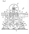
- An underfloor wheel set lathe 1 which is firmly connected to a foundation 2, is used for reprofiling the wheel tire outlines 3, 4 of a wheel set 6 installed in a rail vehicle 5.
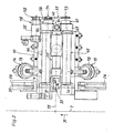
- the underfloor wheelset lathe 1 has two machine units 9, 10 arranged symmetrically to the center 7 of a track 8, each of which has a pair of friction rollers 11, 12 with two swivel drives 13, 14, 15, 16 and a rotary drive 17, 18, a hold-down device 19 , 20 and a support device 21, 22 for an axle bearing box 23, 24 of the wheel set 6.
- the track 8 each include two entry rails 25, 26 and exit rails 27, 28 and two bridging rails 29, 30 for bridging the area between the entry rails 25, 26 and exit rails 27, 28.
- the bridging rails 29, 30 are arranged to be displaceable in the direction of the track 31 so that they can be removed from the working area of the two rotating supports 32, 33.
- the pairs of friction rollers 11, 12 each consist of two friction rollers 34, 35, 36, 37, each of which sits on a shaft 39, 40, 41, 42 arranged parallel to the axle 38 of the wheelset.
- Each shaft 39, 40, 41, 42 is mounted twice in a rocker 43, 44, 45, 46 with a pivot axis 47, 48, 49, 50 running parallel to the axle 38.
- rockers 43, 44, 45, 46 are each articulated to a swivel drive 13, 14, 15, 16.
- the friction rollers 34, 35, 36, 37 of each pair of friction rollers 11, 12 are connected to a rotary drive 17, 18, which has a motor 51, 52, a transfer case 57, 58 consisting of two belt drives 53, 54, 55, 56 and two spur gears 59, 60, 61, 62.
- Each spur gear 59, 60, 61, 62 is a slip-on gear
- the hollow output shaft 63, 64, 65, 66 is plugged onto a shaft 39, 40, 41, 42.
- each spur gear 59, 60, 61, 62 is firmly connected to a rocker 43, 44, 45, 46 by screws (not shown).
- each spur gear 59, 60, 61, 62 is arranged axially with a pivot axis 47, 48, 49, 50, so that during the pivoting movement of the friction rollers 34, 35, 36, 37 Center distances of the belt drives 53, 54, 55, 56 remain unchanged (Fig. 5).
- the pivot axes 47, 48, 49, 50 are arranged symmetrically to the machine center 75.
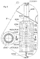
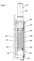
- Each swivel drive 13, 14, 15, 16 has a pneumatic bellows cylinder 76, 77, 78, 79 to generate the swivel movement.
- Two swivel drives 13, 14, 15, 16 assigned to a pair of friction rollers 11, 12 are coupled to a synchronizing device 80, 81.
- Each synchronizing device 80, 81 is composed of a displacement unit 82, 83 and a lever gear 84, 85.
- a lever mechanism 84, 85 includes a slide 86, 87 driven by a displacement unit 82, 83 and two one-armed lever pairs 92, 93, 94, 95, each attached to a pivot shaft 88, 89, 90, 91.
- Each carriage 86, 87 of the two lever mechanisms 84, 85 is formed with four pressure rollers 96, 97, 98, 99, 100, 101, 102, 103 two of which are assigned to a lever 104, 105, 106, 107 of a pair of levers 92, 93, 94, 95.
- each pair of levers 92, 93, 94, 95 is connected in an articulated manner to a swivel drive 13, 14, 15, 16 via a bolt 112, 113, 114, 115, respectively.
- Each lever mechanism 84, 85 contains a switch-off device 116, 117 with a shift rod 120, 121 suspended from a coil spring 118, 119, a shift rod coupling 122, 123 fastened to a slide 86, 87 and a contact switch 124, 125.
- the wheel set 6 When the wheel set 6 was introduced into the underfloor wheel set lathe 1, it was first rolled over the entry rails 25, 26 and the bridging rails 29, 30 in the driving direction 31 over the friction rollers 34, 35, 36, 37. Thereafter, the friction rollers 34, 35, 36, 37 were pressed evenly against the wheel tire outlines 3, 4 by pressurizing the pneumatic bellows cylinders 76, 77, 78, 79.
- the displacement units 82, 83 were actuated, which brought about alignment of the wheel set axis 38 with the machine center 75 and lifting of the wheel set 6 into the position shown in FIGS. 1, 2 and 4 via the lever gears 84, 85.
- the shifting units 82, 83 were switched off by the switch-off devices 116, 117, the shift rods 120, 121 of which were moved downward with the slides 86, 87 to the contact switches 124, 125 while the wheel set 6 was being lifted.
- the bridging rails 29, 30 were moved in the direction of the track 31 from the working area of the rotating supports 32, 33, the two axle boxes 23, 24 of the wheel set 6 by the holding-down device 19, 20 and the support directions 21, 22 locked, the displacement units 82, 83 relieved and the shift rod couplings 122, 123 released (Fig. 1, 3, 4, 6 and 7).
- the rotary supports 32, 33 are moved back one after the other from the working area, the bridging rails 29, 30 are moved into the area between the inlet rails 25, 26 and the outlet rails 27, 28 and the wheel set 6 by pivoting the friction rollers 34 , 35, 36, 37 lowered onto the bridging rails 29, 30.
- the wheel set 6 is then rolled out of the underfloor wheel set lathe 1 via the bridging rails 29, 30 and the outlet rails 27, 28. According to this, the underfloor wheelset lathe 1 is available for reprofiling the wheel tire outlines of another wheelset.
Priority Applications (1)
| Application Number | Priority Date | Filing Date | Title |
|---|---|---|---|
| AT86100807T ATE54851T1 (de) | 1985-03-27 | 1986-01-22 | Unterflur-radsatzdrehmaschine. |
Applications Claiming Priority (2)
| Application Number | Priority Date | Filing Date | Title |
|---|---|---|---|
| DE8509180U | 1985-03-27 | ||
| DE8509180U DE8509180U1 (de) | 1985-03-27 | 1985-03-27 | Unterflur-Radsatzdrehmaschine zum Reprofilieren der Radreifenumrisse von Eisenbahn-Radsätzen |
Publications (3)
| Publication Number | Publication Date |
|---|---|
| EP0195891A2 true EP0195891A2 (fr) | 1986-10-01 |
| EP0195891A3 EP0195891A3 (en) | 1988-06-22 |
| EP0195891B1 EP0195891B1 (fr) | 1990-07-25 |
Family
ID=6779268
Family Applications (1)
| Application Number | Title | Priority Date | Filing Date |
|---|---|---|---|
| EP86100807A Expired - Lifetime EP0195891B1 (fr) | 1985-03-27 | 1986-01-22 | Tour à roues en fosse |
Country Status (8)
| Country | Link |
|---|---|
| US (1) | US4674370A (fr) |
| EP (1) | EP0195891B1 (fr) |
| KR (1) | KR940005393B1 (fr) |
| AT (1) | ATE54851T1 (fr) |
| DE (2) | DE8509180U1 (fr) |
| IN (1) | IN163768B (fr) |
| PL (1) | PL147119B1 (fr) |
| SU (1) | SU1471936A3 (fr) |
Cited By (4)
| Publication number | Priority date | Publication date | Assignee | Title |
|---|---|---|---|---|
| EP0445518A1 (fr) * | 1990-03-03 | 1991-09-11 | Hoesch Maschinenfabrik Deutschland Aktiengesellschaft | Toir à roues, en fosse pour reprofiler des roues des essieux de chemin de fer |
| DE4330811A1 (de) * | 1993-09-12 | 1995-03-16 | Niles Simmons Industrieanlagen | Radsatzausrichtverfahren für Radsatzbearbeitungsmaschinen und Radsatzausrichteinrichtung |
| CN102581609A (zh) * | 2012-02-24 | 2012-07-18 | 无锡市顺达物流涂装设备有限公司 | 用于发动机与变速箱齿轮对接的升降摆动滚床 |
| EP3043937B1 (fr) | 2013-09-09 | 2019-10-30 | Stadler Service Nederland B.V. | Appareil mobile pour usiner deux roues d'essieux |
Families Citing this family (10)
| Publication number | Priority date | Publication date | Assignee | Title |
|---|---|---|---|---|
| DE8817200U1 (de) * | 1988-03-18 | 1994-03-03 | Hoesch Maschinenfabrik Ag | Drehmaschine zur Bearbeitung eines aus einem Schienenfahrzeug ausgebauten Radsatzes |
| EP0711618A1 (fr) * | 1994-11-09 | 1996-05-15 | HEGENSCHEIDT-MFD GmbH | Procédé d'usinage d'un essieu et équipement pour la mise en oeuvre du procédé |
| DE102004044372B4 (de) * | 2004-09-10 | 2008-09-11 | Hegenscheidt-Mfd Gmbh & Co. Kg | Werkzeug zum Bearbeiten von Radreifenprofilen |
| DE102005001220B4 (de) * | 2005-01-10 | 2007-12-13 | Hegenscheidt-Mfd Gmbh & Co. Kg | Unterflurradsatzdrehmaschine zum Bearbeiten von Radsätzen für Eisenbahnfahrzeuge |
| ES2267397B1 (es) * | 2005-08-04 | 2007-12-16 | Dano Rail, S. Coop | Torno de foso para ruedas de ferrocarril. |
| EP2161177B1 (fr) * | 2008-09-09 | 2011-11-02 | EuroMaint AB | Dispositif de levage |
| DE102014200835A1 (de) | 2014-01-17 | 2015-07-23 | Siemens Aktiengesellschaft | Radsatz für ein Schienenfahrzeug |
| WO2017223548A1 (fr) * | 2016-06-25 | 2017-12-28 | Hjr Equipment Rental Inc. | Système et procédé de centrage de roue de locomotive à entraînement par frottement |
| EP3737520A1 (fr) | 2018-01-11 | 2020-11-18 | Simmons Machine Tool Corporation | Système de reprofilage d'un train de roues d'un véhicule ferroviaire |
| EP3575001B3 (fr) * | 2018-05-28 | 2022-09-14 | Bühler AG | Jeux de cylindres pour dispositifs de broyage, dispositifs de broyage et procédé |
Citations (4)
| Publication number | Priority date | Publication date | Assignee | Title |
|---|---|---|---|---|
| FR1278741A (fr) * | 1960-11-04 | 1961-12-15 | Sncf | Dispositif de centrage automatique, dans un plan vertical, des essieux d'engins ferroviaires en cours d'usinage sur un banc dit de reprofilage en place |
| DE2021820A1 (de) * | 1970-05-05 | 1971-11-18 | Hegenscheidt Kg Wilhelm | Unterflur-Radsatzdrehmaschine |
| FR2350921A1 (fr) * | 1976-05-12 | 1977-12-09 | Hegenscheidt Gmbh Wilhelm | Procede de centrage des essieux montes |
| DE8433487U1 (de) * | 1984-11-15 | 1985-03-14 | Hoesch Ag, 4600 Dortmund | Unterflur-radsatzdrehmaschine zum reprofilieren der radreifenumrisse von eisenbahn-radsaetzen |
Family Cites Families (5)
| Publication number | Priority date | Publication date | Assignee | Title |
|---|---|---|---|---|
| US3598017A (en) * | 1969-03-10 | 1971-08-10 | Stanray Corp | Wheel truing machine |
| DE2937819C2 (de) * | 1979-09-19 | 1982-05-06 | Wilhelm Hegenscheidt, Gmbh, 5140 Erkelenz | Unterflurradsatzdrehmaschine |
| DE3012996C2 (de) * | 1980-04-03 | 1982-07-01 | Wilhelm Hegenscheidt, Gmbh, 5140 Erkelenz | Rollenanordnung in Drehmaschinen zum Reprofilieren von Radsätzen |
| DE3012997C2 (de) * | 1980-04-03 | 1983-11-10 | Wilhelm Hegenscheidt Gmbh, 5140 Erkelenz | Unterflurradsatzdrehmaschine |
| DE3102091A1 (de) * | 1981-01-23 | 1982-08-12 | Wilhelm Hegenscheidt, Gmbh, 5140 Erkelenz | Verfahren zum reprofilieren der raeder eines eisenbahnradsatzes durch umfangsfraesen |
-
1985
- 1985-03-27 DE DE8509180U patent/DE8509180U1/de not_active Expired
-
1986
- 1986-01-22 AT AT86100807T patent/ATE54851T1/de not_active IP Right Cessation
- 1986-01-22 DE DE8686100807T patent/DE3672858D1/de not_active Expired - Lifetime
- 1986-01-22 EP EP86100807A patent/EP0195891B1/fr not_active Expired - Lifetime
- 1986-03-10 SU SU864027061A patent/SU1471936A3/ru active
- 1986-03-20 IN IN227/CAL/86A patent/IN163768B/en unknown
- 1986-03-25 PL PL1986258603A patent/PL147119B1/pl unknown
- 1986-03-27 US US06/844,720 patent/US4674370A/en not_active Expired - Fee Related
- 1986-03-27 KR KR1019860002284A patent/KR940005393B1/ko not_active IP Right Cessation
Patent Citations (4)
| Publication number | Priority date | Publication date | Assignee | Title |
|---|---|---|---|---|
| FR1278741A (fr) * | 1960-11-04 | 1961-12-15 | Sncf | Dispositif de centrage automatique, dans un plan vertical, des essieux d'engins ferroviaires en cours d'usinage sur un banc dit de reprofilage en place |
| DE2021820A1 (de) * | 1970-05-05 | 1971-11-18 | Hegenscheidt Kg Wilhelm | Unterflur-Radsatzdrehmaschine |
| FR2350921A1 (fr) * | 1976-05-12 | 1977-12-09 | Hegenscheidt Gmbh Wilhelm | Procede de centrage des essieux montes |
| DE8433487U1 (de) * | 1984-11-15 | 1985-03-14 | Hoesch Ag, 4600 Dortmund | Unterflur-radsatzdrehmaschine zum reprofilieren der radreifenumrisse von eisenbahn-radsaetzen |
Non-Patent Citations (1)
| Title |
|---|
| "Railway Engineer International", März/April 1980 Seiten 38 -40 * |
Cited By (6)
| Publication number | Priority date | Publication date | Assignee | Title |
|---|---|---|---|---|
| EP0445518A1 (fr) * | 1990-03-03 | 1991-09-11 | Hoesch Maschinenfabrik Deutschland Aktiengesellschaft | Toir à roues, en fosse pour reprofiler des roues des essieux de chemin de fer |
| DE4330811A1 (de) * | 1993-09-12 | 1995-03-16 | Niles Simmons Industrieanlagen | Radsatzausrichtverfahren für Radsatzbearbeitungsmaschinen und Radsatzausrichteinrichtung |
| US5664469A (en) * | 1993-09-12 | 1997-09-09 | Niles-Simmons Industrieanlagen Gmbh | Wheelset aligning technique for wheelset truing machinery and wheelset aligning device |
| CN102581609A (zh) * | 2012-02-24 | 2012-07-18 | 无锡市顺达物流涂装设备有限公司 | 用于发动机与变速箱齿轮对接的升降摆动滚床 |
| CN102581609B (zh) * | 2012-02-24 | 2016-01-06 | 无锡顺达智能自动化工程股份有限公司 | 用于发动机与变速箱齿轮对接的升降摆动滚床 |
| EP3043937B1 (fr) | 2013-09-09 | 2019-10-30 | Stadler Service Nederland B.V. | Appareil mobile pour usiner deux roues d'essieux |
Also Published As
| Publication number | Publication date |
|---|---|
| SU1471936A3 (ru) | 1989-04-07 |
| EP0195891A3 (en) | 1988-06-22 |
| US4674370A (en) | 1987-06-23 |
| DE3672858D1 (de) | 1990-08-30 |
| EP0195891B1 (fr) | 1990-07-25 |
| KR860007051A (ko) | 1986-10-06 |
| IN163768B (fr) | 1988-11-05 |
| PL147119B1 (en) | 1989-04-29 |
| KR940005393B1 (ko) | 1994-06-18 |
| ATE54851T1 (de) | 1990-08-15 |
| DE8509180U1 (de) | 1985-06-20 |
Similar Documents
| Publication | Publication Date | Title |
|---|---|---|
| DE2411299C3 (de) | Maschine zum Manipulieren von Platten, insbes. zum Entstapeln von Spanplatten | |
| EP0195891A2 (fr) | Tour à roues en fosse | |
| EP0445518B1 (fr) | Toir à roues, en fosse pour reprofiler des roues des essieux de chemin de fer | |
| EP0181456B1 (fr) | Tour à roues, en fosse, pour le reprofilage des contours de bandage d'essieux ferroviaires | |
| CH635151A5 (de) | Gleisverfahrbare maschine zum bearbeiten der schienenkopfoberflaechen. | |
| EP0185850A2 (fr) | Tour à roues, en fosse, pour le reprofilage des contours de bandage d'essieux ferroviaires | |
| DE3230833C2 (de) | Vorrichtung mit mehreren Arbeitsstationen zum Bedrucken, Ausstanzen bzw. Zuschneiden von Kartonzuschnitten | |
| DE4437541C2 (de) | Schleifmaschine | |
| DE4015366C1 (fr) | ||
| DE3207403A1 (de) | Antriebsvorrichtung fuer die rakelbewegung in siebdruckmaschinen | |
| EP0338217B1 (fr) | Dispositif auxiliaire pour l'usinage de freins à disque d'une paire de roue de chemin de fer sur un tour à roue | |
| DE4038129C1 (en) | Double-shaft circular saw with conveyor track - has saw blades in working station and compression mechanism independently vertically adjustable | |
| DE3607323A1 (de) | Automatisch umruestbarer greifertransfer fuer pressen mit schiebetischen | |
| DE2509693C3 (de) | Richtungsgleistransporteinrichtung | |
| DE1277069B (de) | Vorrichtung zum Glaetten der Schienenkopfoberflaechen von Eisenbahnschienen | |
| DE3035612A1 (de) | Einrichtung zum runden der ecken von glasplatten | |
| DE19850999C1 (de) | Vorrichtung zum automatischen Wechseln von Werkzeugen für eine Umformpresse | |
| DE2258198C3 (de) | Herstellungsmaschine für Schraubennahtrohre | |
| DE2504110C3 (de) | Einrichtung zum Ausschneiden von flachen Figuren | |
| DE2347279C3 (de) | Vorrichtung zum Antrieb oder Abbremsen von auf Schienen geführten Fahrzeugen, insbesondere Tunnelofenwagen | |
| DE2423789C3 (de) | Vorrichtung zum Räumen des Schotters aus Gleisbettungen | |
| EP1710031A1 (fr) | Machine de reprofilage de roues et/ou de freins à disque des essieux d'un véhicule ferroviaire | |
| DE1021746B (de) | Schleifvorrichtung fuer Eisenbahnschienen | |
| DE435862C (de) | Rangierverfahren fuer Kohlen- oder Eisenbahnwagen auf Verladebahnhoefen | |
| DE302972C (fr) |
Legal Events
| Date | Code | Title | Description |
|---|---|---|---|
| PUAI | Public reference made under article 153(3) epc to a published international application that has entered the european phase |
Free format text: ORIGINAL CODE: 0009012 |
|
| AK | Designated contracting states |
Kind code of ref document: A2 Designated state(s): AT BE CH DE FR GB IT LI LU NL SE |
|
| ITCL | It: translation for ep claims filed |
Representative=s name: RICCARDI SERGIO & CO. |
|
| TCNL | Nl: translation of patent claims filed | ||
| EL | Fr: translation of claims filed | ||
| RIN1 | Information on inventor provided before grant (corrected) |
Inventor name: GUTOEHRLEIN, UWE, DIPL.-ING. Inventor name: BRINKMANN, DIRK, DIPL.-ING. |
|
| PUAL | Search report despatched |
Free format text: ORIGINAL CODE: 0009013 |
|
| AK | Designated contracting states |
Kind code of ref document: A3 Designated state(s): AT BE CH DE FR GB IT LI LU NL SE |
|
| 17P | Request for examination filed |
Effective date: 19880714 |
|
| 17Q | First examination report despatched |
Effective date: 19890518 |
|
| GRAA | (expected) grant |
Free format text: ORIGINAL CODE: 0009210 |
|
| AK | Designated contracting states |
Kind code of ref document: B1 Designated state(s): AT BE CH DE FR GB IT LI LU NL SE |
|
| REF | Corresponds to: |
Ref document number: 54851 Country of ref document: AT Date of ref document: 19900815 Kind code of ref document: T |
|
| REF | Corresponds to: |
Ref document number: 3672858 Country of ref document: DE Date of ref document: 19900830 |
|
| ET | Fr: translation filed | ||
| GBT | Gb: translation of ep patent filed (gb section 77(6)(a)/1977) | ||
| ITF | It: translation for a ep patent filed |
Owner name: UFFICIO BREVETTI RICCARDI & C. |
|
| PGFP | Annual fee paid to national office [announced via postgrant information from national office to epo] |
Ref country code: LU Payment date: 19910108 Year of fee payment: 6 |
|
| EPTA | Lu: last paid annual fee | ||
| PLBE | No opposition filed within time limit |
Free format text: ORIGINAL CODE: 0009261 |
|
| STAA | Information on the status of an ep patent application or granted ep patent |
Free format text: STATUS: NO OPPOSITION FILED WITHIN TIME LIMIT |
|
| 26N | No opposition filed | ||
| PG25 | Lapsed in a contracting state [announced via postgrant information from national office to epo] |
Ref country code: LU Free format text: LAPSE BECAUSE OF NON-PAYMENT OF DUE FEES Effective date: 19920122 |
|
| ITTA | It: last paid annual fee | ||
| PGFP | Annual fee paid to national office [announced via postgrant information from national office to epo] |
Ref country code: CH Payment date: 19941214 Year of fee payment: 10 |
|
| PGFP | Annual fee paid to national office [announced via postgrant information from national office to epo] |
Ref country code: SE Payment date: 19941219 Year of fee payment: 10 |
|
| PGFP | Annual fee paid to national office [announced via postgrant information from national office to epo] |
Ref country code: BE Payment date: 19941220 Year of fee payment: 10 Ref country code: AT Payment date: 19941220 Year of fee payment: 10 |
|
| EAL | Se: european patent in force in sweden |
Ref document number: 86100807.6 |
|
| PGFP | Annual fee paid to national office [announced via postgrant information from national office to epo] |
Ref country code: NL Payment date: 19950131 Year of fee payment: 10 |
|
| PG25 | Lapsed in a contracting state [announced via postgrant information from national office to epo] |
Ref country code: AT Effective date: 19960122 |
|
| PG25 | Lapsed in a contracting state [announced via postgrant information from national office to epo] |
Ref country code: SE Effective date: 19960123 |
|
| PG25 | Lapsed in a contracting state [announced via postgrant information from national office to epo] |
Ref country code: LI Effective date: 19960131 Ref country code: CH Effective date: 19960131 Ref country code: BE Effective date: 19960131 |
|
| BERE | Be: lapsed |
Owner name: HOESCH MASCHINENFABRIK DEUTSCHLAND A.G. Effective date: 19960131 |
|
| PG25 | Lapsed in a contracting state [announced via postgrant information from national office to epo] |
Ref country code: NL Effective date: 19960801 |
|
| REG | Reference to a national code |
Ref country code: CH Ref legal event code: PL |
|
| NLV4 | Nl: lapsed or anulled due to non-payment of the annual fee |
Effective date: 19960801 |
|
| EUG | Se: european patent has lapsed |
Ref document number: 86100807.6 |
|
| PGFP | Annual fee paid to national office [announced via postgrant information from national office to epo] |
Ref country code: GB Payment date: 19971211 Year of fee payment: 13 |
|
| PGFP | Annual fee paid to national office [announced via postgrant information from national office to epo] |
Ref country code: FR Payment date: 19971231 Year of fee payment: 13 |
|
| PG25 | Lapsed in a contracting state [announced via postgrant information from national office to epo] |
Ref country code: GB Free format text: LAPSE BECAUSE OF NON-PAYMENT OF DUE FEES Effective date: 19990122 |
|
| GBPC | Gb: european patent ceased through non-payment of renewal fee |
Effective date: 19990122 |
|
| PG25 | Lapsed in a contracting state [announced via postgrant information from national office to epo] |
Ref country code: FR Free format text: LAPSE BECAUSE OF NON-PAYMENT OF DUE FEES Effective date: 19990930 |
|
| REG | Reference to a national code |
Ref country code: FR Ref legal event code: ST |
|
| PGFP | Annual fee paid to national office [announced via postgrant information from national office to epo] |
Ref country code: DE Payment date: 20021129 Year of fee payment: 18 |
|
| PG25 | Lapsed in a contracting state [announced via postgrant information from national office to epo] |
Ref country code: DE Free format text: LAPSE BECAUSE OF NON-PAYMENT OF DUE FEES Effective date: 20040803 |
|
| PG25 | Lapsed in a contracting state [announced via postgrant information from national office to epo] |
Ref country code: IT Free format text: LAPSE BECAUSE OF NON-PAYMENT OF DUE FEES;WARNING: LAPSES OF ITALIAN PATENTS WITH EFFECTIVE DATE BEFORE 2007 MAY HAVE OCCURRED AT ANY TIME BEFORE 2007. THE CORRECT EFFECTIVE DATE MAY BE DIFFERENT FROM THE ONE RECORDED. Effective date: 20050122 |