EP0195891A2 - Under-floor wheel lathe - Google Patents
Under-floor wheel lathe Download PDFInfo
- Publication number
- EP0195891A2 EP0195891A2 EP86100807A EP86100807A EP0195891A2 EP 0195891 A2 EP0195891 A2 EP 0195891A2 EP 86100807 A EP86100807 A EP 86100807A EP 86100807 A EP86100807 A EP 86100807A EP 0195891 A2 EP0195891 A2 EP 0195891A2
- Authority
- EP
- European Patent Office
- Prior art keywords
- swivel
- friction rollers
- wheel
- wheel set
- pair
- Prior art date
- Legal status (The legal status is an assumption and is not a legal conclusion. Google has not performed a legal analysis and makes no representation as to the accuracy of the status listed.)
- Granted
Links
- 238000006073 displacement reaction Methods 0.000 claims description 6
- 230000001360 synchronised effect Effects 0.000 claims description 2
- 230000008878 coupling Effects 0.000 description 3
- 238000010168 coupling process Methods 0.000 description 3
- 238000005859 coupling reaction Methods 0.000 description 3
- 230000007246 mechanism Effects 0.000 description 3
- 230000000284 resting effect Effects 0.000 description 1
Images


Classifications
-
- B—PERFORMING OPERATIONS; TRANSPORTING
- B23—MACHINE TOOLS; METAL-WORKING NOT OTHERWISE PROVIDED FOR
- B23B—TURNING; BORING
- B23B5/00—Turning-machines or devices specially adapted for particular work; Accessories specially adapted therefor
- B23B5/28—Turning-machines or devices specially adapted for particular work; Accessories specially adapted therefor for turning wheels or wheel sets or cranks thereon, i.e. wheel lathes
- B23B5/32—Turning-machines or devices specially adapted for particular work; Accessories specially adapted therefor for turning wheels or wheel sets or cranks thereon, i.e. wheel lathes for reconditioning wheel sets without removing same from the vehicle; Underfloor wheel lathes for railway vehicles
-
- Y—GENERAL TAGGING OF NEW TECHNOLOGICAL DEVELOPMENTS; GENERAL TAGGING OF CROSS-SECTIONAL TECHNOLOGIES SPANNING OVER SEVERAL SECTIONS OF THE IPC; TECHNICAL SUBJECTS COVERED BY FORMER USPC CROSS-REFERENCE ART COLLECTIONS [XRACs] AND DIGESTS
- Y10—TECHNICAL SUBJECTS COVERED BY FORMER USPC
- Y10T—TECHNICAL SUBJECTS COVERED BY FORMER US CLASSIFICATION
- Y10T82/00—Turning
- Y10T82/18—Lathe for wheel or axle
Landscapes
- Engineering & Computer Science (AREA)
- Mechanical Engineering (AREA)
- Turning (AREA)
- Tires In General (AREA)
- Dowels (AREA)
- Scissors And Nippers (AREA)
- Rollers For Roller Conveyors For Transfer (AREA)
- Friction Gearing (AREA)
- Moulds For Moulding Plastics Or The Like (AREA)
- Transmission Devices (AREA)
Abstract
Eine Unterflur-Radsatzdrehmaschine zum Reprofilieren der Radreifenumrisse von Eisenbahn-Radsätzen, mit zwei angetriebenen Reibrollenpaaren, die je an einen Radreifenumriß eines Radsatzes andrückbar sind, wobei die Reibrollen eines jeden Reibrollenpaares einzeln mit je einem Schwenkantrieb verbunden und um je eine parallel zur Radsatzachse angeordnete Schwenkachse schwenkbar sind, zeichnet sich zum gleichmäßigen Andrücken der Reibrollen und zum automatischen Ausrichten der Radsatzachse dadurch aus, daß jeder Schwenkantrieb (13, 14, 15, 16) zur Erzeugung der Schwenkbewegung einen PneumatikBalgzylinder (76, 77, 78, 79) aufweist und daß jeweils zwei einem Reibrollenpaar (11, 12) zugeordnete Schwenkantriebe (13, 14, 15, 16) an eine Gleichlaufvorrichtung (80, 81) gekuppelt sind.An underfloor wheel set lathe for re-profiling the wheel tire outlines of railroad wheel sets, with two driven friction roller pairs, each of which can be pressed onto a wheel tire outline of a wheel set, the friction rollers of each pair of friction rollers being individually connected to a swivel drive and pivoting about a swivel axis arranged parallel to the wheel set axis characterized for evenly pressing the friction rollers and for automatically aligning the axle of the wheelset in that each swivel drive (13, 14, 15, 16) has a pneumatic bellows cylinder (76, 77, 78, 79) to generate the swivel movement, and that two swivel drives (13, 14, 15, 16) assigned to a pair of friction rollers (11, 12) are coupled to a synchronizing device (80, 81).
Description
Die Neuerung bezieht sich auf eine Unterflur-Radsatzdrehmaschine zum Reprofilieren der Radreifenumrisse von Eisenbahn-Radsätzen, mit zwei angetriebenen Reibrollenpaaren, die je an einen Radreifenumriß eines Radsatzes andrückbar sind, wobei die Reibrollen eines jeden Reibrollenpaares einzeln mit je einem Schwenkantrieb verbunden und um je eine parallel zur Radsatzachse angeordnete Schwenkachse schwenkbar sind.The innovation relates to an underfloor wheelset lathe for re-profiling the wheel tire outlines of railroad wheel sets, with two driven friction roller pairs, each of which can be pressed onto a wheel tire outline of a wheel set, the friction rollers of each pair of friction rollers being individually connected to a swivel drive and by one parallel arranged to the axle set pivot axis are pivotable.
Bei einer Unterflur-Radsatzdrehmaschine nach dem DE-GM 84 33 487 werden die Schwenkantriebe eingesetzt zum Andrücken der Reibrollen an die Radreifenumrisse des Radsatzes, ferner zum Hochheben und Absenken des Radsatzes sowie zum Ausrichten der Radsatzachse auf die Maschinenmitte.In an underfloor wheelset lathe according to DE-GM 84 33 487, the swivel drives are used to press the friction rollers against the wheel tire outline of the wheelset, also to raise and lower the wheelset and to align the wheelset axis to the center of the machine.
Es hat sich herausgestellt, daß die in dieser Uhterflur-Radsatzdrehmaschine eingesetzten Schwenkantriebe zum gleichmäßigen Andrücken der Reibrollen an die Radreifehumrisse des Radsatzes und zum automatischen Ausrichten der Radsatzachse auf die Maschinenmitte nicht gut geeignet sind.It has been found that the swivel drives used in this underfloor wheelset lathe are not well suited for evenly pressing the friction rollers against the wheel rim contours of the wheelset and for automatically aligning the wheelset axis with the center of the machine.
Der Neuerung liegt die Aufgabe zugrunde, die Schwenkantriebe einer Unterflur-Radsatzdrehmaschine der eingangs genannten Art so auszubilden, daß sie zum gleichmäßigeh Andrücken der Reibrollen an die Radreifenumrisse des Radsatzes und zum automatischen Ausrichten der Radsatzachse auf die Maschinenmitte gut geeignet sind.The innovation is based on the task of designing the swivel drives of an underfloor wheelset lathe of the type mentioned in such a way that they are well suited for evenly pressing the friction rollers against the wheel tire contours of the wheelset and for automatically aligning the wheelset axis with the center of the machine.
Neuerungsgemäß wird diese Aufgabe dadurch gelöst, daß jeder Schwenkantrieb zur Erzeugung der Schwenkbewegung einen Pneumatik-Balgzylinder aufweist und daß jeweils zwei einem Reibrollenpaar zugeordnete Schwenkantriebe an eine Gleichlaufvorrichtung gekuppelt sind.According to the invention, this object is achieved in that each swivel drive for generating the swivel movement has a pneumatic bellows cylinder and in that two swivel drives assigned to a pair of friction rollers are coupled to a synchronous device.
Vorteilhafte Ausgestaltungen der Neuerung sind in den Unteransprüchen erfaßt.Advantageous refinements of the innovation are covered in the subclaims.
Im folgenden wird die Neuerung anhand einer Zeichnung, in der ein Ausführungsbeispiel schematisch dargestellt ist, näher beschrieben.The innovation is described in more detail below with reference to a drawing in which an exemplary embodiment is shown schematically.
Es zeigt
- Fig. 1 eine Unterflur-Radsatzdrehmaschine und einen von ihr aufgenommenen Radsatz in Ansicht mit einer Teilansicht eines auf dem Radsatz aufliegenden Fahrzeugaufbaus, mit einem Schnitt durch zwei Einlaufschienen und zwei Schienenträger und mit einem Teilschnitt durch ein Fundament,
- Fig.2 die rechte Maschineneinheit der Unterflur-Radsatzdrehmaschine im Grundriß mit strichpunktierter Darstellung des rechten Radreifenumrisses des aufgenommenen Radsatzes in vergrößertem Maßstab,
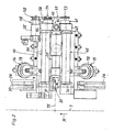
- Fig. 3 einen Schnitt entsprechend der Linie III-III in Fig. 1 in vergrößertem Maßstab,
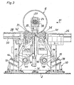
- Fig. 4 eine Seitenansicht der Unterflur-Radsetzdrehmaschine und des von ihr aufgenommenen Radsatzes in Richtung des Pfeiles A in Fig. 1 mit einem Teilschnitt durch das Fundament in vergrößertem Maßstab,
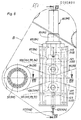
- Fig. 5 einen Schnitt durch die rechte Maschineneinheit der Unterflur-Radsetzdrehmaschine entsprechend der Linie V-V in Fig. 4,
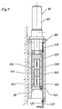
- Fig. 6 einen Teilausschnitt B der Fig. 4 in vergrößertem Maßstab,
- Fig. 7 einen Teilschnitt entsprechend der Linie VII-VII in Fig. 6,
- Fig. 8 einen Teilschnitt entsprechend der Linie VIII-VIII in Fig. 6.
- 1 is an underfloor wheelset lathe and a wheel set it has in view with a partial view of a vehicle body resting on the wheel set, with a section through two inlet rails and two rail supports and with a partial section through a foundation,
- 2 shows the right machine unit of the underfloor wheelset lathe in plan view with dash-dotted lines of the right wheel tire outline of the wheelset taken up on an enlarged scale,
- 3 shows a section along the line III-III in FIG. 1 on an enlarged scale,
- 4 shows a side view of the underfloor wheel setting lathe and the wheel set it receives in the direction of arrow A in FIG. 1 with a partial section through the foundation on an enlarged scale,
- Fig. 5 is a section through the right engine unit of U-nterflur Radsetzdrehmaschine according to the line VV in Fig. 4,
- 6 is a partial section B of FIG. 4 on an enlarged scale,
- 7 is a partial section along the line VII-VII in Fig. 6,
- 8 is a partial section along the line VIII-VIII in Fig. 6th
Eine Unterflur-Radsatzdrehmaschine 1, die fest mit einem Fundament 2 verbunden ist, wird eingesetzt zum Reprofilieren der Radreifenumrisse 3, 4 eines in einem Schienenfahrzeug 5 eingebauten Radsatzes 6.An underfloor wheel set
Die Unterflur-Radsatzdrehmaschine 1 hat zwei symmetrisch zur Mitte 7 eines Fahrgleises 8 angeordnete Maschineneinheiten 9, 10, von denen jede ein Reibrollenpaar 11, 12 mit zwei Schwenk-antrieben 13, 14, 15, 16 und einem Drehantrieb 17, 18, eine Niederhaltevorrichtung 19, 20 sowie eine Stützvorrichtung 21, 22 für einen Achslagerkasten 23, 24 des Radsatzes 6 aufweist.The
Zu dem Fahrgleis 8 gehören je zwei Einlaufschienen 25, 26 und Auslaufschienen 27, 28 sowie zwei Überbrückungsschienen 29, 30 zum Überbrücken des Bereichs zwischen den Einlaufschienen 25, 26 und Auslaufschienen 27, 28.The
Die Uberbrückungsschienen 29, 30 sind in Fahrgleisrichtung 31 verschiebbar angeordnet, damit sie aus dem Arbeitsbereich der beiden Drehsupporte 32, 33 entfernt werden können.The
Die Reibrollenpaare 11, 12 bestehen aus je zwei Reibrollen 34, 35, 36, 37 von denen jede auf einer parallel zur Radsatzachse 38 angeordneten Welle 39, 40, 41, 42 sitzt.The pairs of
Jede Welle 39, 40, 41, 42 ist zweifach in einer Schwinge 43, 44, 45, 46 mit einer parallel zur Radsatzachse 38 verlaufenden Schwenkachse 47, 48, 49, 50 gelagert.Each
Die Schwingen 43, 44, 45, 46 sind jeweils an einen Schwenkantrieb 13, 14, 15, 16 gelenkig angeschlossen.The
Die Reibrollen 34, 35, 36, 37 eines jeden Reibrollenpaares 11, 12 sind mit einem Drehantrieb 17, 18 verbunden, der einen Motor 51, 52, ein aus zwei Riementrieben 53, 54, 55, 56 bestehendes Verteilergetriebe 57, 58 und zwei Stirnradgetriebe 59, 60, 61, 62 aufweist.The
Alle Stirnradgetriebe 59, 60, 61, 62 sind völlig gleich ausgeführt.All
Jedes Stirnradgetriebe 59, 60, 61, 62 ist ein Aufsteckgetriebe, dessen hohle Abtriebswelle 63, 64, 65, 66 auf eine Welle 39, 40, 41, 42 gesteckt ist.Each
Das Gehäuse 67, 68, 69, 70 eines jeden Stirnradgetriebes 59, 60, 61, 62 ist durch Schrauben (nicht dargestellt) fest mit einer Schwinge 43, 44, 45, 46 verbunden.The
Die Eingangswelle 71, 72, 73, 74 eines jeden Stirnradgetrie--bes 59, 60, 61, 62 ist achsgleich zu einer Schwenkachse 47, 48, 49, 50 angeordnet, damit während der Schwenkbewegung der Reibrollen 34, 35, 36, 37 die Achsabstände der Riementriebe 53, 54, 55, 56 unverändert bleiben (Fig. 5).The
Die Schwenkachsen 47, 48, 49, 50 sind symmetrisch zur Maschinenmitte 75 angeordnet.The
Jeder Schwenkantrieb 13, 14, 15, 16 besitzt zur Erzeugung der Schwenkbewegung einen Pneumatik-Balgzylinder 76, 77, 78, 79.Each
Jeweils zwei einem Reibrollenpaar 11, 12 zugeordnete Schwenkantriebe 13, 14, 15, 16 sind an eine Gleichlaufvorrichtung 80, 81 gekuppelt.Two swivel drives 13, 14, 15, 16 assigned to a pair of
Jede Gleichlaufvorrichtung 80, 81 setzt sich aus einer Verschiebeeinheit 82, 83 und einem Hebelgetriebe 84, 85 zusammen.Each synchronizing
Zu einem Hebelgetriebe 84, 85 gehören ein von einer Verschiebeeinheit 82, 83 angetriebener Schlitten 86, 87 und zwei einarmige, an je einer Schwenkwelle 88, 89, 90, 91 befestigte Hebelpaare 92, 93, 94, 95.A
Jeder Schlitten 86, 87 der beiden Hebelgetriebe 84, 85 ist mit vier Druckrollen 96, 97, 98, 99, 100, 101, 102, 103 ausgebildet von denen je zwei einem Hebel 104, 105, 106, 107 eines Hebelpaares 92, 93, 94, 95 zugeordnet sind.Each
Der andere Hebel 108, 109, 110, 111 eines jeden Hebelpaares 92, 93, 94, 95 ist über je einen Bolzen 112, 113, 114, 115 gelenkig an einen Schwenkantrieb 13, 14, 15, 16 angeschlossen.The
Jedes Hebelgetriebe 84, 85 enthält eine Abschaltvorrichtung 116, 117 mit einer an einer Schraubenfeder 118, 119 aufgehängten Schaltstange 120, 121, einer an einem Schlitten 86, 87 befestigten-Schaltstangenkupplung 122, 123 und einem Kontaktschalter 124, 125.Each
Beim Einbringen des Radsatzes 6 in die Unterflur-Radsatzdrehmaschine 1 wurde er zunächst über die Einlaufschienen 25, 26 und die Überbrückungsschienen 29, 30 in Fahrgldisrichtung 31 über die Reibrollen 34, 35, 36, 37 gerollt. Danach wurden die Reibrollen 34, 35, 36, 37 durch Druckluftbeaufschlagung der Pneumatik-Balgzylinder 76, 77, 78, 79 gleichmäßig an die Radreifenumrisse 3, 4 angedrückt.When the
Anschließend wurden die Verschiebeeinheiten 82, 83 betätigt, die über die Hebelgetriebe 84, 85 ein Ausrichten der Radsatzachse 38 auf die Maschinenmitte 75 und ein Hochheben des Radsatzes 6 in die in den Fig. 1, 2 und 4 dargestellte Position bewirkten.Subsequently, the
Das Abschalten der Verschiebeeinheiten 82, 83 erfolgte durch die Abschaltvorrichtungen 116, 117, deren Schaltstangen 120, 121 während des Hochhebens des Radsatzes 6 mit den Schlitten 86, 87 nach unten zu den Kontaktschaltern 124, 125 bewegt wurden.The shifting
In der angehobenen Stellung des Radsatzes 6 wurden nacheinander die Überbrückungsschienen 29, 30 in Fahrgleisrichtung 31 aus dem Arbeitsbereich der Drehsupporte 32, 33 bewegt, die beiden Achslagerkästen 23, 24 des Radsatzes 6 durch die Niederhaltevorrichtung 19, 20 und die Stützvorrichtungen 21, 22 arretiert, die Verschiebeeinheiten 82, 83 entlastet und die Schaltstangenkupplungen 122, 123 gelöst (Fig. 1, 3, 4, 6 und 7).In the raised position of the wheel set 6, the
In der in den Fig. 1, 3 und 4 dargestellten Position des Radsatzes 6 erfolgt die Reprofilierung der Radreifenumrisse 3, 4 durch die Drehsupporte 32, 33. Hierbei erteilen die Drehantriebe 17, 18 den Reibrollen 34, 35, 36, 37 und dem Radsatz 6 eine Drehbewegung.In the position of the
Nach der Reprofilierung der Radreifenumrisse 3, 4 werden nacheinander die Drehsupporte 32, 33 aus dem Arbeitsbereich zurückgefahren, die Überbrückungsschienen 29, 30 in den Bereich zwischen die Einlaufschienen 25, 26 und die Auslaufschienen 27, 28 bewegt und der Radsatz 6 durch Verschwenken der Reibrollen 34, 35, 36, 37 auf die Überbrückungsschienen 29, 30 abgesenkt.After the re-profiling of the wheel tire outlines 3, 4, the rotary supports 32, 33 are moved back one after the other from the working area, the
Anschließend wird der Radsatz 6 über die Überbrückungsschienen 29, 30 und die Auslaufschienen 27, 28 aus der Unterflur-Radsatzdrehmaschine 1 gerollt. Hiernach steht die Unterflur-Radsatzdrehmaschine 1 zur Reprofilierung der Radreifenumrisse eines anderen Radsatzes zur Verfügung.The
- 1 Unterflur-Radsatzdrehmaschine1 underfloor wheelset lathe
- 2 Fundament2 foundation
- 3, 4 Radreifenumriß3, 4 wheel tire outline
- 5 Schienenfahrzeug5 rail vehicle
- 6 Radsatz6 wheelset
- 7 Mitte7 middle
- 8 Fahrgleis8 track
- 9, 10 Maschineneinheit9, 10 machine unit
- 11, 12 Reibrollenpaar11, 12 pair of friction rollers
- 13, 14,13, 14,
- 15, 16 Schwenkantrieb15, 16 rotary actuator
- 17, 18 Drehantrieb17, 18 rotary drive
- 19, 20 Niederhaltevorrichtung19, 20 hold-down device
- 21, 22 Stützvorrichtung21, 22 support device
- 23, 24 Achslagerkasten23, 24 axle box
- 25, 26 Einlaufschiene25, 26 infeed rail
- 27, 28 Auslaufschiene27, 28 outlet rail
- 29, 30 Überbrückungsschiene29, 30 bridging rail
- 31 Fahrgleisrichtung31 direction of travel
- 32, 33 Drehsupport32, 33 turning support
- 34, 35,34, 35,
- 36, 37 Reibrolle36, 37 friction roller
- 38 Radsatzachse38 axle set
- 39, 40,39, 40,
- 41, 42 Welle41, 42 shaft
- 43, 44,43, 44,
- 45, 46 Schwinge45, 46 swingarm
- 47, 48,47, 48,
- 49, 50 Schwenkachse49, 50 swivel axis
- 51, 52 Motor51, 52 engine
- 53, 54,53, 54,
- 55, 56 Riementrieb55, 56 belt drive
- 57, 58 Verteilergetriebe57, 58 transfer case
- 59, 60,59, 60,
- 61, 62 Stirnradgetriebe61, 62 spur gear
- 63, 64,63, 64,
- 65, 66 Abtriebswelle65, 66 output shaft
- 67, 68,67, 68,
- 69, 70 Gehäuse69, 70 housing
- 71, 72,71, 72,
- 73, 74 Eingangswelle73, 74 input shaft
- 75 Maschinenmitte75 machine center
- 76, 77,76, 77,
- 78, 79 Pneumatik-Balgzylinder78, 79 pneumatic bellows cylinders
- 80, 81 Gleichlaufvorrichtung80, 81 synchronization device
- 82, 83 Verschiebeeinheit82, 83 displacement unit
- 84, 85 Hebelgetriebe84, 85 lever gear
- 86, 87 Schlitten86, 87 sledge
- 88, 89,88, 89,
- 90, 91 Schwenkwelle90, 91 pivot shaft
- 92, 93,92, 93,
- 94, 95 Hebelpaar94, 95 pair of levers
- 96, 97,96, 97,
- 98, 99,98, 99,
- 100, 101,100, 101,
- 102, 103 Druckrolle102, 103 pressure roller
- 104, 105,104, 105,
- 106, 107 Hebel106, 107 lever
- 108, 109,108, 109,
- 110, 111 Hebel110, 111 lever
- 112, 113,112, 113,
- 114, 115 Bolzen114, 115 bolts
- 116, 117 Abschaltvorrichtung116, 117 switch-off device
- 118, 119 Schraubenfeder118, 119 coil spring
- 120, 121 Schaltstange120, 121 shift rod
- 122, 123 Schaltstangenkupplung122, 123 shift rod coupling
- 124, 125 Kontaktschalter124, 125 contact switches
Claims (3)
Priority Applications (1)
| Application Number | Priority Date | Filing Date | Title |
|---|---|---|---|
| AT86100807T ATE54851T1 (en) | 1985-03-27 | 1986-01-22 | UNDERFLOOR WHEEL SET LATHE. |
Applications Claiming Priority (2)
| Application Number | Priority Date | Filing Date | Title |
|---|---|---|---|
| DE8509180U DE8509180U1 (en) | 1985-03-27 | 1985-03-27 | Underfloor wheelset lathe for reprofiling the wheel tire outlines of railway wheelsets |
| DE8509180U | 1985-03-27 |
Publications (3)
| Publication Number | Publication Date |
|---|---|
| EP0195891A2 true EP0195891A2 (en) | 1986-10-01 |
| EP0195891A3 EP0195891A3 (en) | 1988-06-22 |
| EP0195891B1 EP0195891B1 (en) | 1990-07-25 |
Family
ID=6779268
Family Applications (1)
| Application Number | Title | Priority Date | Filing Date |
|---|---|---|---|
| EP86100807A Expired - Lifetime EP0195891B1 (en) | 1985-03-27 | 1986-01-22 | Under-floor wheel lathe |
Country Status (8)
| Country | Link |
|---|---|
| US (1) | US4674370A (en) |
| EP (1) | EP0195891B1 (en) |
| KR (1) | KR940005393B1 (en) |
| AT (1) | ATE54851T1 (en) |
| DE (2) | DE8509180U1 (en) |
| IN (1) | IN163768B (en) |
| PL (1) | PL147119B1 (en) |
| SU (1) | SU1471936A3 (en) |
Cited By (4)
| Publication number | Priority date | Publication date | Assignee | Title |
|---|---|---|---|---|
| EP0445518A1 (en) * | 1990-03-03 | 1991-09-11 | Hoesch Maschinenfabrik Deutschland Aktiengesellschaft | Underfloor wheel lathe for reprofiling the wheels of railway-wheelsets |
| DE4330811A1 (en) * | 1993-09-12 | 1995-03-16 | Niles Simmons Industrieanlagen | Wheelset-aligning method for wheelset machine tools and wheelset-aligning equipment |
| CN102581609A (en) * | 2012-02-24 | 2012-07-18 | 无锡市顺达物流涂装设备有限公司 | Lifting swinging rolling machine for butt joint of gears of engine and gearbox |
| EP3043937B1 (en) | 2013-09-09 | 2019-10-30 | Stadler Service Nederland B.V. | Mobile device for machining two wheels of a wheelset |
Families Citing this family (10)
| Publication number | Priority date | Publication date | Assignee | Title |
|---|---|---|---|---|
| DE3809250C1 (en) * | 1988-03-18 | 1989-07-13 | Hoesch Maschinenfabrik Deutschland Ag, 4600 Dortmund, De | |
| EP0711618A1 (en) * | 1994-11-09 | 1996-05-15 | HEGENSCHEIDT-MFD GmbH | Process for machining a wheel-set and equipment for the application of that process |
| DE102004044372B4 (en) * | 2004-09-10 | 2008-09-11 | Hegenscheidt-Mfd Gmbh & Co. Kg | Tool for editing wheel tire profiles |
| DE102005001220B4 (en) * | 2005-01-10 | 2007-12-13 | Hegenscheidt-Mfd Gmbh & Co. Kg | Underfloor wheel lathe for machining wheel sets for railway vehicles |
| ES2267397B1 (en) * | 2005-08-04 | 2007-12-16 | Dano Rail, S. Coop | FOSO LATHE FOR RAILWAY WHEELS. |
| EP2161177B1 (en) * | 2008-09-09 | 2011-11-02 | EuroMaint AB | A lifting device |
| DE102014200835A1 (en) * | 2014-01-17 | 2015-07-23 | Siemens Aktiengesellschaft | Wheel set for a rail vehicle |
| WO2017223548A1 (en) * | 2016-06-25 | 2017-12-28 | Hjr Equipment Rental Inc. | Friction drive locomotive wheel truing system and method |
| WO2019140053A1 (en) | 2018-01-11 | 2019-07-18 | Simmons Machine Tool Corporation | System for reprofiling a wheel set of a railway vehicle |
| EP3597300B1 (en) * | 2018-05-28 | 2021-03-31 | Bühler AG | Rolling packets for milling devices, milling devices and method |
Citations (4)
| Publication number | Priority date | Publication date | Assignee | Title |
|---|---|---|---|---|
| FR1278741A (en) * | 1960-11-04 | 1961-12-15 | Sncf | Device for automatic centering, in a vertical plane, of the axles of railway vehicles being machined on a so-called reprofiling bench in place |
| DE2021820A1 (en) * | 1970-05-05 | 1971-11-18 | Hegenscheidt Kg Wilhelm | Underfloor wheelset lathe |
| FR2350921A1 (en) * | 1976-05-12 | 1977-12-09 | Hegenscheidt Gmbh Wilhelm | CENTERING PROCEDURE FOR MOUNTED AXLES |
| DE8433487U1 (en) * | 1984-11-15 | 1985-03-14 | Hoesch Ag, 4600 Dortmund | UNDERFLOOR WHEEL SET LATHE FOR REPROFILING THE WHEEL TIRE OUTLINE OF RAILWAY WHEEL SETS |
Family Cites Families (5)
| Publication number | Priority date | Publication date | Assignee | Title |
|---|---|---|---|---|
| US3598017A (en) * | 1969-03-10 | 1971-08-10 | Stanray Corp | Wheel truing machine |
| DE2937819C2 (en) * | 1979-09-19 | 1982-05-06 | Wilhelm Hegenscheidt, Gmbh, 5140 Erkelenz | Underfloor wheel set lathe |
| DE3012997C2 (en) * | 1980-04-03 | 1983-11-10 | Wilhelm Hegenscheidt Gmbh, 5140 Erkelenz | Underfloor wheel set lathe |
| DE3012996C2 (en) * | 1980-04-03 | 1982-07-01 | Wilhelm Hegenscheidt, Gmbh, 5140 Erkelenz | Roller arrangement in lathes for reprofiling wheelsets |
| DE3102091A1 (en) * | 1981-01-23 | 1982-08-12 | Wilhelm Hegenscheidt, Gmbh, 5140 Erkelenz | METHOD FOR REPROFILING THE WHEELS OF A RAILWAY WHEEL SET BY CIRCULAR MILLING |
-
1985
- 1985-03-27 DE DE8509180U patent/DE8509180U1/en not_active Expired
-
1986
- 1986-01-22 EP EP86100807A patent/EP0195891B1/en not_active Expired - Lifetime
- 1986-01-22 AT AT86100807T patent/ATE54851T1/en not_active IP Right Cessation
- 1986-01-22 DE DE8686100807T patent/DE3672858D1/en not_active Expired - Lifetime
- 1986-03-10 SU SU864027061A patent/SU1471936A3/en active
- 1986-03-20 IN IN227/CAL/86A patent/IN163768B/en unknown
- 1986-03-25 PL PL1986258603A patent/PL147119B1/en unknown
- 1986-03-27 KR KR1019860002284A patent/KR940005393B1/en not_active IP Right Cessation
- 1986-03-27 US US06/844,720 patent/US4674370A/en not_active Expired - Fee Related
Patent Citations (4)
| Publication number | Priority date | Publication date | Assignee | Title |
|---|---|---|---|---|
| FR1278741A (en) * | 1960-11-04 | 1961-12-15 | Sncf | Device for automatic centering, in a vertical plane, of the axles of railway vehicles being machined on a so-called reprofiling bench in place |
| DE2021820A1 (en) * | 1970-05-05 | 1971-11-18 | Hegenscheidt Kg Wilhelm | Underfloor wheelset lathe |
| FR2350921A1 (en) * | 1976-05-12 | 1977-12-09 | Hegenscheidt Gmbh Wilhelm | CENTERING PROCEDURE FOR MOUNTED AXLES |
| DE8433487U1 (en) * | 1984-11-15 | 1985-03-14 | Hoesch Ag, 4600 Dortmund | UNDERFLOOR WHEEL SET LATHE FOR REPROFILING THE WHEEL TIRE OUTLINE OF RAILWAY WHEEL SETS |
Non-Patent Citations (1)
| Title |
|---|
| "Railway Engineer International", März/April 1980 Seiten 38 -40 * |
Cited By (6)
| Publication number | Priority date | Publication date | Assignee | Title |
|---|---|---|---|---|
| EP0445518A1 (en) * | 1990-03-03 | 1991-09-11 | Hoesch Maschinenfabrik Deutschland Aktiengesellschaft | Underfloor wheel lathe for reprofiling the wheels of railway-wheelsets |
| DE4330811A1 (en) * | 1993-09-12 | 1995-03-16 | Niles Simmons Industrieanlagen | Wheelset-aligning method for wheelset machine tools and wheelset-aligning equipment |
| US5664469A (en) * | 1993-09-12 | 1997-09-09 | Niles-Simmons Industrieanlagen Gmbh | Wheelset aligning technique for wheelset truing machinery and wheelset aligning device |
| CN102581609A (en) * | 2012-02-24 | 2012-07-18 | 无锡市顺达物流涂装设备有限公司 | Lifting swinging rolling machine for butt joint of gears of engine and gearbox |
| CN102581609B (en) * | 2012-02-24 | 2016-01-06 | 无锡顺达智能自动化工程股份有限公司 | The lifting and swinging docked with gearbox gear for engine rolls bed |
| EP3043937B1 (en) | 2013-09-09 | 2019-10-30 | Stadler Service Nederland B.V. | Mobile device for machining two wheels of a wheelset |
Also Published As
| Publication number | Publication date |
|---|---|
| PL147119B1 (en) | 1989-04-29 |
| EP0195891B1 (en) | 1990-07-25 |
| EP0195891A3 (en) | 1988-06-22 |
| ATE54851T1 (en) | 1990-08-15 |
| SU1471936A3 (en) | 1989-04-07 |
| IN163768B (en) | 1988-11-05 |
| DE8509180U1 (en) | 1985-06-20 |
| DE3672858D1 (en) | 1990-08-30 |
| KR940005393B1 (en) | 1994-06-18 |
| US4674370A (en) | 1987-06-23 |
| KR860007051A (en) | 1986-10-06 |
Similar Documents
| Publication | Publication Date | Title |
|---|---|---|
| DE2411299C3 (en) | Machine for manipulating panels, especially for destacking chipboard | |
| EP0195891A2 (en) | Under-floor wheel lathe | |
| EP0445518B1 (en) | Underfloor wheel lathe for reprofiling the wheels of railway-wheelsets | |
| EP0181456B1 (en) | Underfloor wheelset lathe for reprofiling the contours of wheel rims of railway wheel sets | |
| CH635151A5 (en) | TRACKABLE MACHINE FOR MACHINING THE RAIL HEAD SURFACES. | |
| EP0185850A2 (en) | Underfloor wheelset lathe for reprofiling the contours of wheel rims of railway wheelsets | |
| DE3230833C2 (en) | Device with several work stations for printing, punching or cutting of cardboard blanks | |
| DE4437541C2 (en) | Grinding machine | |
| DE4015366C1 (en) | ||
| EP0243706A2 (en) | Device for cleaning cylinders in a rotary printing machine | |
| DE3207403A1 (en) | Drive device for the doctor movement in screen-printing machines | |
| EP0338217B1 (en) | Auxiliary device for working the brake discs of a railway wheel pair on a railway wheel lathe | |
| DE4038129C1 (en) | Double-shaft circular saw with conveyor track - has saw blades in working station and compression mechanism independently vertically adjustable | |
| DE3607323A1 (en) | Automatically convertible feed bar transfer for presses with sliding tables | |
| DE2509693C3 (en) | Directional track transport device | |
| DE1277069B (en) | Device for smoothing the rail head surfaces of railroad tracks | |
| DE3035612A1 (en) | DEVICE FOR ROUNDING THE CORNERS OF GLASS PANELS | |
| DE19850999C1 (en) | Automatic changing appliance has changing plate for molding implement, press-bedplate, drive cog wheel, toothed bar and chain drive | |
| DE2258198C3 (en) | Manufacturing machine for screw sutures | |
| DE2504110C3 (en) | Device for cutting out flat figures | |
| DE2347279C3 (en) | Device for driving or braking vehicles guided on rails, in particular tunnel kiln cars | |
| DE2423789C3 (en) | Device for clearing ballast from track beds | |
| EP1710031A1 (en) | Machine for reprofiling the wheels and/or brake disks of railway vehicle wheelsets | |
| DE1021746B (en) | Grinding device for railroad tracks | |
| DE435862C (en) | Shunting procedures for coal or railway wagons at loading stations |
Legal Events
| Date | Code | Title | Description |
|---|---|---|---|
| PUAI | Public reference made under article 153(3) epc to a published international application that has entered the european phase |
Free format text: ORIGINAL CODE: 0009012 |
|
| AK | Designated contracting states |
Kind code of ref document: A2 Designated state(s): AT BE CH DE FR GB IT LI LU NL SE |
|
| ITCL | It: translation for ep claims filed |
Representative=s name: RICCARDI SERGIO & CO. |
|
| TCNL | Nl: translation of patent claims filed | ||
| EL | Fr: translation of claims filed | ||
| RIN1 | Information on inventor provided before grant (corrected) |
Inventor name: GUTOEHRLEIN, UWE, DIPL.-ING. Inventor name: BRINKMANN, DIRK, DIPL.-ING. |
|
| PUAL | Search report despatched |
Free format text: ORIGINAL CODE: 0009013 |
|
| AK | Designated contracting states |
Kind code of ref document: A3 Designated state(s): AT BE CH DE FR GB IT LI LU NL SE |
|
| 17P | Request for examination filed |
Effective date: 19880714 |
|
| 17Q | First examination report despatched |
Effective date: 19890518 |
|
| GRAA | (expected) grant |
Free format text: ORIGINAL CODE: 0009210 |
|
| AK | Designated contracting states |
Kind code of ref document: B1 Designated state(s): AT BE CH DE FR GB IT LI LU NL SE |
|
| REF | Corresponds to: |
Ref document number: 54851 Country of ref document: AT Date of ref document: 19900815 Kind code of ref document: T |
|
| REF | Corresponds to: |
Ref document number: 3672858 Country of ref document: DE Date of ref document: 19900830 |
|
| ET | Fr: translation filed | ||
| GBT | Gb: translation of ep patent filed (gb section 77(6)(a)/1977) | ||
| ITF | It: translation for a ep patent filed |
Owner name: UFFICIO BREVETTI RICCARDI & C. |
|
| PGFP | Annual fee paid to national office [announced via postgrant information from national office to epo] |
Ref country code: LU Payment date: 19910108 Year of fee payment: 6 |
|
| EPTA | Lu: last paid annual fee | ||
| PLBE | No opposition filed within time limit |
Free format text: ORIGINAL CODE: 0009261 |
|
| STAA | Information on the status of an ep patent application or granted ep patent |
Free format text: STATUS: NO OPPOSITION FILED WITHIN TIME LIMIT |
|
| 26N | No opposition filed | ||
| PG25 | Lapsed in a contracting state [announced via postgrant information from national office to epo] |
Ref country code: LU Free format text: LAPSE BECAUSE OF NON-PAYMENT OF DUE FEES Effective date: 19920122 |
|
| ITTA | It: last paid annual fee | ||
| PGFP | Annual fee paid to national office [announced via postgrant information from national office to epo] |
Ref country code: CH Payment date: 19941214 Year of fee payment: 10 |
|
| PGFP | Annual fee paid to national office [announced via postgrant information from national office to epo] |
Ref country code: SE Payment date: 19941219 Year of fee payment: 10 |
|
| PGFP | Annual fee paid to national office [announced via postgrant information from national office to epo] |
Ref country code: BE Payment date: 19941220 Year of fee payment: 10 Ref country code: AT Payment date: 19941220 Year of fee payment: 10 |
|
| EAL | Se: european patent in force in sweden |
Ref document number: 86100807.6 |
|
| PGFP | Annual fee paid to national office [announced via postgrant information from national office to epo] |
Ref country code: NL Payment date: 19950131 Year of fee payment: 10 |
|
| PG25 | Lapsed in a contracting state [announced via postgrant information from national office to epo] |
Ref country code: AT Effective date: 19960122 |
|
| PG25 | Lapsed in a contracting state [announced via postgrant information from national office to epo] |
Ref country code: SE Effective date: 19960123 |
|
| PG25 | Lapsed in a contracting state [announced via postgrant information from national office to epo] |
Ref country code: LI Effective date: 19960131 Ref country code: CH Effective date: 19960131 Ref country code: BE Effective date: 19960131 |
|
| BERE | Be: lapsed |
Owner name: HOESCH MASCHINENFABRIK DEUTSCHLAND A.G. Effective date: 19960131 |
|
| PG25 | Lapsed in a contracting state [announced via postgrant information from national office to epo] |
Ref country code: NL Effective date: 19960801 |
|
| REG | Reference to a national code |
Ref country code: CH Ref legal event code: PL |
|
| NLV4 | Nl: lapsed or anulled due to non-payment of the annual fee |
Effective date: 19960801 |
|
| EUG | Se: european patent has lapsed |
Ref document number: 86100807.6 |
|
| PGFP | Annual fee paid to national office [announced via postgrant information from national office to epo] |
Ref country code: GB Payment date: 19971211 Year of fee payment: 13 |
|
| PGFP | Annual fee paid to national office [announced via postgrant information from national office to epo] |
Ref country code: FR Payment date: 19971231 Year of fee payment: 13 |
|
| PG25 | Lapsed in a contracting state [announced via postgrant information from national office to epo] |
Ref country code: GB Free format text: LAPSE BECAUSE OF NON-PAYMENT OF DUE FEES Effective date: 19990122 |
|
| GBPC | Gb: european patent ceased through non-payment of renewal fee |
Effective date: 19990122 |
|
| PG25 | Lapsed in a contracting state [announced via postgrant information from national office to epo] |
Ref country code: FR Free format text: LAPSE BECAUSE OF NON-PAYMENT OF DUE FEES Effective date: 19990930 |
|
| REG | Reference to a national code |
Ref country code: FR Ref legal event code: ST |
|
| PGFP | Annual fee paid to national office [announced via postgrant information from national office to epo] |
Ref country code: DE Payment date: 20021129 Year of fee payment: 18 |
|
| PG25 | Lapsed in a contracting state [announced via postgrant information from national office to epo] |
Ref country code: DE Free format text: LAPSE BECAUSE OF NON-PAYMENT OF DUE FEES Effective date: 20040803 |
|
| PG25 | Lapsed in a contracting state [announced via postgrant information from national office to epo] |
Ref country code: IT Free format text: LAPSE BECAUSE OF NON-PAYMENT OF DUE FEES;WARNING: LAPSES OF ITALIAN PATENTS WITH EFFECTIVE DATE BEFORE 2007 MAY HAVE OCCURRED AT ANY TIME BEFORE 2007. THE CORRECT EFFECTIVE DATE MAY BE DIFFERENT FROM THE ONE RECORDED. Effective date: 20050122 |