EP0184635A1 - Revêtement de bords de toits - Google Patents
Revêtement de bords de toits Download PDFInfo
- Publication number
- EP0184635A1 EP0184635A1 EP85113057A EP85113057A EP0184635A1 EP 0184635 A1 EP0184635 A1 EP 0184635A1 EP 85113057 A EP85113057 A EP 85113057A EP 85113057 A EP85113057 A EP 85113057A EP 0184635 A1 EP0184635 A1 EP 0184635A1
- Authority
- EP
- European Patent Office
- Prior art keywords
- web
- clamping piece
- cladding
- profile
- roof edge
- Prior art date
- Legal status (The legal status is an assumption and is not a legal conclusion. Google has not performed a legal analysis and makes no representation as to the accuracy of the status listed.)
- Granted
Links
- 238000005253 cladding Methods 0.000 claims description 51
- 238000007789 sealing Methods 0.000 claims description 5
- 238000004519 manufacturing process Methods 0.000 description 3
- 238000010276 construction Methods 0.000 description 1
- 230000001066 destructive effect Effects 0.000 description 1
- 238000005516 engineering process Methods 0.000 description 1
Images
Classifications
-
- E—FIXED CONSTRUCTIONS
- E04—BUILDING
- E04D—ROOF COVERINGS; SKY-LIGHTS; GUTTERS; ROOF-WORKING TOOLS
- E04D13/00—Special arrangements or devices in connection with roof coverings; Protection against birds; Roof drainage ; Sky-lights
- E04D13/15—Trimming strips; Edge strips; Fascias; Expansion joints for roofs
- E04D13/155—Trimming strips; Edge strips; Fascias; Expansion joints for roofs retaining the roof sheathing
Definitions
- the innovation relates to a roof edge cladding which consists of a cladding profile and an angularly designed clamping piece which can be locked therewith, by means of which the roof skin can be clamped to the cladding profile preferably via a sealing strip inserted in a receiving groove formed on the lower end of the clamping piece.
- a roof edge covering of this type is known from DE-A 1 32 38 879.
- the cladding profile is provided in the upper region with a receiving pocket which is formed on a horizontal leg and runs at an angle to the cladding profile, which is U-shaped and has internal teeth.
- the upper bent end of the clamping piece, which can be inserted into the receiving pocket, is provided with a corresponding counter-toothing, so that the clamping piece can be locked with the cladding profile by the interlocking teeth and thus the roof skin can be tensioned.
- the roof cladding can be reliably fixed to the cladding profile, but a relatively great force is required to press the clamping piece into the receiving pocket, since the contact pressure, by means of which the clamping piece is supposed to act on the roof cladding, must be applied by hand at almost full height. Handling at a construction site is therefore often difficult. Furthermore, the arrangement of the U-shaped receiving pocket on the cladding profile raises pressing problems which can only be solved by additional measures, but which make the production of the cladding profile very expensive.
- a comparable roof edge cladding is known, in which a horizontally projecting web that can be locked with the clamping piece is formed on the cladding profile.
- the tensioning force acting on the roof skin which is to be pressed onto the back of the cladding profile, is also to be applied in this embodiment when the clamping piece is snapped on, and considerable resistances have to be overcome.
- a locking toothing provided on the underside of the projecting web extends over its entire length and a receiving pocket provided on the clamping piece is adapted to the thickness of the web, so that a nose which engages in its toothing and is usually formed over a large part on the lower leg of the receiving pocket the teeth must be pushed away.
- the legs of the receiving pockets are more or less to bend, and a dismantling of the clamping piece without causing damage is usually not possible.
- the object of the innovation is therefore to improve the roof edge cladding of the type mentioned in such a way that the clamping piece can be snapped onto the cladding profile with little effort, but that nevertheless always provides reliable and secure tensioning of the roof cladding and, if appropriate, non-destructive dismantling of the clamping piece are guaranteed.
- the cladding profile and the clamping piece should be able to be pressed without difficulty, so that the individual parts of the roof edge cladding are also economical to manufacture.
- the cladding profile in the upper area has an inwardly projecting, approximately horizontally extending and provided with a downward locking projection retaining web that at the upper end of the clamping piece or a clamping profile or a clamping strip one by two approximately parallel leg formed receiving pocket is attached, and that in the lower leg delimiting the receiving pocket, a toothing is incorporated into which the locking projection provided on the projecting retaining web of the cladding profile engages.
- the receiving pocket of the clamping piece in height greater than the strength of the retaining web engaging in it with ratchet jump, so that an easy introduction is given and the bracing can be accomplished by tilting.
- the upper leg delimiting the receiving pocket of the clamping piece at its free end internally facing bevelled edge, a landing stage or the like it is furthermore expedient to move the upper leg delimiting the receiving pocket of the clamping piece at its free end internally facing bevelled edge, a landing stage or the like.
- the length of the lower leg of the receiving pocket should be shorter than its upper leg and the projected opening width between the bend of the upper leg and the lower leg should correspond in height to approximately the thickness of the retaining web formed on the cladding profile with a locking projection. In this way, an alignment of the individual components aligned with one another is ensured in spite of the fact that the receiving chambers have to be dimensioned large in terms of press technology.
- the cladding profile should be provided by means of an integrally formed connecting web which is inclined in a partial area to the roof surface, and the receiving groove, which is attached to the lower end of the clamping profile and carries the sealing strip, should have an inclination corresponding to the inclined part of the connecting web. so that the roof skin can be clamped on this part by means of the clamping piece.
- the roof edge cladding designed according to the innovation is not only economically producible, since the cladding profile and the clamping piece can be pressed without difficulty, but the proposed design allows, above all, always secure tensioning of the roof skin without a great effort being required to snap the clamping piece on .
- the clamping piece is only more or less to be pushed onto the retaining web of the cladding profile in order to allow a satisfactory pressing of the roof skin.
- the clamping piece can also be easily and without being damaged, for example, when the roof skin is renewed. It is therefore always easy to use.
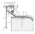
- the roof edge cladding designated 1 serves to cover the upper roof edge 4 of a building 2 and to brace a roof skin 6 laid on its roof surface 3 and consists of a cladding profile 11 and a clamping piece 21 which can be locked with the cladding profile 11.
- a connecting web 12 is formed on it, which extends in a partial area inclined to the roof surface 3 and is fastened to the building 2 by means of screws 5.
- the clamping piece 21 is of an angular design and is provided at its upper end with a receiving pocket 24 formed by two legs 22 and 23 running parallel to one another and at its lower end with a receiving groove 28 for a sealing strip 29 created by a projecting web 27. Furthermore, the lower leg 23 of the receiving pocket 24, which is shorter than its upper leg 22, has an internal toothing 25, the upper leg 22, on the other hand, is equipped at its end with an inwardly bent edge 26.
- a horizontally protruding retaining web 13 is integrally formed thereon, at the end of which a downwardly directed latching projection 14, which cooperates with the toothing 25 of the leg 23, is formed.
- the clear height h of the receiving pocket 24 is dimensioned larger than the thickness S of the retaining web 13 with the locking projection 14, on the other hand corresponds to projected opening width between the fold 26 of the upper leg 22 and the lower leg 23 of the thickness S of the retaining web 13 with locking projection 14.
- the clamping piece 21 is easy to manufacture by pressing, since the distance between the two legs 22 and 23 is kept large can be, but this can also be pushed onto the retaining web 13 of the cladding profile 11 without difficulty and with little effort and still securely locked with it, the clamping piece 21 being arranged in alignment with the cladding profile 11 in the installed position. And since the receiving groove 28 runs parallel to the inclined part of the connecting web 12, the roof skin 6 is always securely braced with the cladding profile 11.
Landscapes
- Engineering & Computer Science (AREA)
- Architecture (AREA)
- Civil Engineering (AREA)
- Structural Engineering (AREA)
- Roof Covering Using Slabs Or Stiff Sheets (AREA)
- Fittings On The Vehicle Exterior For Carrying Loads, And Devices For Holding Or Mounting Articles (AREA)
- Vehicle Interior And Exterior Ornaments, Soundproofing, And Insulation (AREA)
- Sealing Battery Cases Or Jackets (AREA)
- Seal Device For Vehicle (AREA)
Priority Applications (1)
| Application Number | Priority Date | Filing Date | Title |
|---|---|---|---|
| AT85113057T ATE42787T1 (de) | 1984-11-13 | 1985-10-15 | Dachrandverkleidung. |
Applications Claiming Priority (2)
| Application Number | Priority Date | Filing Date | Title |
|---|---|---|---|
| DE8433179U | 1984-11-13 | ||
| DE19848433179U DE8433179U1 (de) | 1984-11-13 | 1984-11-13 | Dachrandverkleidung |
Publications (2)
| Publication Number | Publication Date |
|---|---|
| EP0184635A1 true EP0184635A1 (fr) | 1986-06-18 |
| EP0184635B1 EP0184635B1 (fr) | 1989-05-03 |
Family
ID=6772644
Family Applications (1)
| Application Number | Title | Priority Date | Filing Date |
|---|---|---|---|
| EP85113057A Expired EP0184635B1 (fr) | 1984-11-13 | 1985-10-15 | Revêtement de bords de toits |
Country Status (3)
| Country | Link |
|---|---|
| EP (1) | EP0184635B1 (fr) |
| AT (1) | ATE42787T1 (fr) |
| DE (2) | DE8433179U1 (fr) |
Cited By (1)
| Publication number | Priority date | Publication date | Assignee | Title |
|---|---|---|---|---|
| DE102018009461A1 (de) | 2018-12-05 | 2020-06-10 | Klaus Peter Abel | Randabschlussvorrichtung für biegsame Sperrschichten |
Families Citing this family (1)
| Publication number | Priority date | Publication date | Assignee | Title |
|---|---|---|---|---|
| DE102024101991A1 (de) * | 2024-01-24 | 2025-07-24 | Emdatec Gmbh | Dachrandabschlussprofil zur Befestigung einer Dachabdichtung auf einem Flachdach |
Citations (3)
| Publication number | Priority date | Publication date | Assignee | Title |
|---|---|---|---|---|
| US2260438A (en) * | 1938-12-21 | 1941-10-28 | Cheney Allan | Waterproofed building construction |
| FR1551549A (fr) * | 1967-07-18 | 1968-12-27 | ||
| DE2333959A1 (de) * | 1973-07-04 | 1975-01-16 | Halfeneisen Gmbh & Co Kg | Vorrichtung zur bildung eines die dachhaut bei flachdaechern ueber der rohdecke abschliessenden randes |
-
1984
- 1984-11-13 DE DE19848433179U patent/DE8433179U1/de not_active Expired
-
1985
- 1985-10-15 EP EP85113057A patent/EP0184635B1/fr not_active Expired
- 1985-10-15 AT AT85113057T patent/ATE42787T1/de active
- 1985-10-15 DE DE8585113057T patent/DE3569950D1/de not_active Expired
Patent Citations (3)
| Publication number | Priority date | Publication date | Assignee | Title |
|---|---|---|---|---|
| US2260438A (en) * | 1938-12-21 | 1941-10-28 | Cheney Allan | Waterproofed building construction |
| FR1551549A (fr) * | 1967-07-18 | 1968-12-27 | ||
| DE2333959A1 (de) * | 1973-07-04 | 1975-01-16 | Halfeneisen Gmbh & Co Kg | Vorrichtung zur bildung eines die dachhaut bei flachdaechern ueber der rohdecke abschliessenden randes |
Cited By (1)
| Publication number | Priority date | Publication date | Assignee | Title |
|---|---|---|---|---|
| DE102018009461A1 (de) | 2018-12-05 | 2020-06-10 | Klaus Peter Abel | Randabschlussvorrichtung für biegsame Sperrschichten |
Also Published As
| Publication number | Publication date |
|---|---|
| ATE42787T1 (de) | 1989-05-15 |
| DE3569950D1 (en) | 1989-06-08 |
| DE8433179U1 (de) | 1985-02-28 |
| EP0184635B1 (fr) | 1989-05-03 |
Similar Documents
| Publication | Publication Date | Title |
|---|---|---|
| DE8102895U1 (de) | Profil fuer eine aussenleiste von einer blinddecke oder vorsatzwand | |
| DE3400110C2 (fr) | ||
| DE29808197U1 (de) | Entwässerungsrinne | |
| DE29600057U1 (de) | Fugenprofil für Fußbodenbeläge | |
| CH460296A (de) | Kantenabdeckung für Flachdächer, Schrägdächer, Terrassenböden und dergleichen | |
| DE2910325A1 (de) | Halter fuer schutzgelaender | |
| EP0184635B1 (fr) | Revêtement de bords de toits | |
| DE4239051C2 (de) | Gebäudewandverkleidung | |
| DE29916138U1 (de) | Leistenanordnung zum Abdecken oder Überbrücken von Fugen, insbesondere für Fußböden | |
| EP3658721B1 (fr) | Dispositif de recouvrement pour des revêtements de sol | |
| DE3910647C2 (de) | Bausatz | |
| DE1659340B2 (de) | Ortgangverkleidung fuer flachdaecher od.dgl | |
| DE8915947U1 (de) | Befestigungsvorrichtung für Fassadenplatten, insbesondere Fassadenziegel | |
| DE8524910U1 (de) | Konsolanker zur höhenverstellbaren Abfangung von Verblendmauerwerk | |
| DE2727289A1 (de) | Gebaeudeverkleidung | |
| DE29501224U1 (de) | Unterkonstruktion für mit Dachplatten eingedeckte Steildächer | |
| DE8633382U1 (de) | Verschließbarer Dachlastträger | |
| DE1659329C3 (de) | Abdeckung für Mauern o.dgl | |
| DE8705794U1 (de) | Dacheindeckung aus Kunststoff | |
| DE2624120C3 (de) | Vorrichtung zum gemeinsamen Befestigen einer Traufenblende und einer Dachrinne an einem Schrägdach | |
| DE2255950A1 (de) | Einstueckige dachrandverkleidung | |
| DE2150398C3 (de) | Höhenverstellbare Halterung für das Verkleidungsprofil einer Ortgangverkleidung | |
| DE2924805A1 (de) | Putzprofilleiste | |
| DE20103079U1 (de) | Dämmung für eine Gebäudewand | |
| EP0315811A1 (fr) | Attache de fixation pour un couvre-mur |
Legal Events
| Date | Code | Title | Description |
|---|---|---|---|
| PUAI | Public reference made under article 153(3) epc to a published international application that has entered the european phase |
Free format text: ORIGINAL CODE: 0009012 |
|
| AK | Designated contracting states |
Kind code of ref document: A1 Designated state(s): AT BE DE FR NL |
|
| 17P | Request for examination filed |
Effective date: 19861114 |
|
| 17Q | First examination report despatched |
Effective date: 19880212 |
|
| GRAA | (expected) grant |
Free format text: ORIGINAL CODE: 0009210 |
|
| AK | Designated contracting states |
Kind code of ref document: B1 Designated state(s): AT BE DE FR NL |
|
| REF | Corresponds to: |
Ref document number: 42787 Country of ref document: AT Date of ref document: 19890515 Kind code of ref document: T |
|
| REF | Corresponds to: |
Ref document number: 3569950 Country of ref document: DE Date of ref document: 19890608 |
|
| ET | Fr: translation filed | ||
| PLBE | No opposition filed within time limit |
Free format text: ORIGINAL CODE: 0009261 |
|
| STAA | Information on the status of an ep patent application or granted ep patent |
Free format text: STATUS: NO OPPOSITION FILED WITHIN TIME LIMIT |
|
| 26N | No opposition filed | ||
| NLT1 | Nl: modifications of names registered in virtue of documents presented to the patent office pursuant to art. 16 a, paragraph 1 |
Owner name: HOOGOVENS ALUMINIUM PROFILTECHNIK GMBH TE VOGT, BO |
|
| REG | Reference to a national code |
Ref country code: FR Ref legal event code: CD |
|
| PGFP | Annual fee paid to national office [announced via postgrant information from national office to epo] |
Ref country code: FR Payment date: 19950918 Year of fee payment: 11 |
|
| PGFP | Annual fee paid to national office [announced via postgrant information from national office to epo] |
Ref country code: BE Payment date: 19951110 Year of fee payment: 11 |
|
| PG25 | Lapsed in a contracting state [announced via postgrant information from national office to epo] |
Ref country code: BE Effective date: 19961031 |
|
| BERE | Be: lapsed |
Owner name: HOOGOVENS ALUMINIUM PROFILTECHNIK G.M.B.H. Effective date: 19961031 |
|
| PG25 | Lapsed in a contracting state [announced via postgrant information from national office to epo] |
Ref country code: FR Effective date: 19970630 |
|
| REG | Reference to a national code |
Ref country code: FR Ref legal event code: ST |
|
| PGFP | Annual fee paid to national office [announced via postgrant information from national office to epo] |
Ref country code: AT Payment date: 19971021 Year of fee payment: 13 |
|
| PGFP | Annual fee paid to national office [announced via postgrant information from national office to epo] |
Ref country code: NL Payment date: 19971029 Year of fee payment: 13 |
|
| PG25 | Lapsed in a contracting state [announced via postgrant information from national office to epo] |
Ref country code: AT Free format text: LAPSE BECAUSE OF NON-PAYMENT OF DUE FEES Effective date: 19981015 |
|
| PGFP | Annual fee paid to national office [announced via postgrant information from national office to epo] |
Ref country code: DE Payment date: 19981223 Year of fee payment: 14 |
|
| PG25 | Lapsed in a contracting state [announced via postgrant information from national office to epo] |
Ref country code: NL Free format text: LAPSE BECAUSE OF NON-PAYMENT OF DUE FEES Effective date: 19990501 |
|
| NLV4 | Nl: lapsed or anulled due to non-payment of the annual fee |
Effective date: 19990501 |
|
| PG25 | Lapsed in a contracting state [announced via postgrant information from national office to epo] |
Ref country code: DE Free format text: LAPSE BECAUSE OF NON-PAYMENT OF DUE FEES Effective date: 20000801 |