EP0179066B1 - Multiple threshold wheel slip control apparatus and method - Google Patents
Multiple threshold wheel slip control apparatus and method Download PDFInfo
- Publication number
- EP0179066B1 EP0179066B1 EP84902886A EP84902886A EP0179066B1 EP 0179066 B1 EP0179066 B1 EP 0179066B1 EP 84902886 A EP84902886 A EP 84902886A EP 84902886 A EP84902886 A EP 84902886A EP 0179066 B1 EP0179066 B1 EP 0179066B1
- Authority
- EP
- European Patent Office
- Prior art keywords
- signal
- slip
- value
- response
- reference value
- Prior art date
- Legal status (The legal status is an assumption and is not a legal conclusion. Google has not performed a legal analysis and makes no representation as to the accuracy of the status listed.)
- Expired
Links
- 238000000034 method Methods 0.000 title claims description 8
- 230000004044 response Effects 0.000 claims abstract description 54
- 238000012360 testing method Methods 0.000 claims abstract description 54
- 230000007246 mechanism Effects 0.000 claims abstract description 30
- 230000000694 effects Effects 0.000 abstract description 5
- 239000012530 fluid Substances 0.000 description 15
- 230000009467 reduction Effects 0.000 description 7
- 238000010586 diagram Methods 0.000 description 6
- 238000013459 approach Methods 0.000 description 5
- 230000001965 increasing effect Effects 0.000 description 5
- 230000009471 action Effects 0.000 description 2
- 230000004913 activation Effects 0.000 description 2
- 230000003750 conditioning effect Effects 0.000 description 2
- 230000003247 decreasing effect Effects 0.000 description 2
- 230000006870 function Effects 0.000 description 2
- 238000009987 spinning Methods 0.000 description 2
- 230000005355 Hall effect Effects 0.000 description 1
- 230000008901 benefit Effects 0.000 description 1
- 230000008859 change Effects 0.000 description 1
- 238000010276 construction Methods 0.000 description 1
- 238000013461 design Methods 0.000 description 1
- 230000002708 enhancing effect Effects 0.000 description 1
- 230000003287 optical effect Effects 0.000 description 1
- 238000012163 sequencing technique Methods 0.000 description 1
- 239000007787 solid Substances 0.000 description 1
- 238000012546 transfer Methods 0.000 description 1
- 230000007704 transition Effects 0.000 description 1
Images


Classifications
-
- B—PERFORMING OPERATIONS; TRANSPORTING
- B60—VEHICLES IN GENERAL
- B60T—VEHICLE BRAKE CONTROL SYSTEMS OR PARTS THEREOF; BRAKE CONTROL SYSTEMS OR PARTS THEREOF, IN GENERAL; ARRANGEMENT OF BRAKING ELEMENTS ON VEHICLES IN GENERAL; PORTABLE DEVICES FOR PREVENTING UNWANTED MOVEMENT OF VEHICLES; VEHICLE MODIFICATIONS TO FACILITATE COOLING OF BRAKES
- B60T8/00—Arrangements for adjusting wheel-braking force to meet varying vehicular or ground-surface conditions, e.g. limiting or varying distribution of braking force
- B60T8/17—Using electrical or electronic regulation means to control braking
- B60T8/175—Brake regulation specially adapted to prevent excessive wheel spin during vehicle acceleration, e.g. for traction control
-
- B—PERFORMING OPERATIONS; TRANSPORTING
- B60—VEHICLES IN GENERAL
- B60T—VEHICLE BRAKE CONTROL SYSTEMS OR PARTS THEREOF; BRAKE CONTROL SYSTEMS OR PARTS THEREOF, IN GENERAL; ARRANGEMENT OF BRAKING ELEMENTS ON VEHICLES IN GENERAL; PORTABLE DEVICES FOR PREVENTING UNWANTED MOVEMENT OF VEHICLES; VEHICLE MODIFICATIONS TO FACILITATE COOLING OF BRAKES
- B60T8/00—Arrangements for adjusting wheel-braking force to meet varying vehicular or ground-surface conditions, e.g. limiting or varying distribution of braking force
- B60T8/32—Arrangements for adjusting wheel-braking force to meet varying vehicular or ground-surface conditions, e.g. limiting or varying distribution of braking force responsive to a speed condition, e.g. acceleration or deceleration
- B60T8/34—Arrangements for adjusting wheel-braking force to meet varying vehicular or ground-surface conditions, e.g. limiting or varying distribution of braking force responsive to a speed condition, e.g. acceleration or deceleration having a fluid pressure regulator responsive to a speed condition
- B60T8/48—Arrangements for adjusting wheel-braking force to meet varying vehicular or ground-surface conditions, e.g. limiting or varying distribution of braking force responsive to a speed condition, e.g. acceleration or deceleration having a fluid pressure regulator responsive to a speed condition connecting the brake actuator to an alternative or additional source of fluid pressure, e.g. traction control systems
- B60T8/4809—Traction control, stability control, using both the wheel brakes and other automatic braking systems
Definitions
- This invention relates generally to wheel slip control systems for vehicles having differentially driven wheels in which slip is controlled by application of a braking force to the slipping wheel, and, more particularly, to an apparatus and method having multiple wheel slip threshold levels.
- An alternative approach involves the provision of separately actuatable drive wheel brakes.
- An operator selectively applies a braking force to the spinning or slipping wheel, and effects a balancing of power through the differential mechanism.
- the application of the braking force to the slipping wheel simulates increased traction and results in a more even distribution of power between the differentially driven wheels. This approach is commonly used on farm vehicles.
- a more sophisticated approach to the just described system utilizes electronics to supply the braking force to the slipping or spinning wheel.
- An effective example of this approach is described in our US-A-4,344,139 and US-A-4,361,871, which disclose apparatus for applying a proportionally varying braking force to the wheel which loses traction, during a slip control time period.
- a slip signal is produced corresponding to any difference between the rotational velocity of the differentially driven wheels, and the slip signal is compared with a predetermined reference signal.
- the system selectively applies a braking force to the faster turning wheel.
- the braking force is modulated proportionally according to the degree of slip represented by the slip signal.
- a vehicle having a steering mechanism and an anti-spin apparatus for controllably equalizing the power delivered through a differential mechanism to at least two wheels each having a respective braking mechanism the apparatus including means for receiving a brake control signal and controllably operating the braking mechanisms in response to a received brake control signal, (as disclosed in US-A-4,042,059), is characterized by means for producing a slip signal having a value responsive to the difference in rotational velocity between the wheels; means for producing a test signal; processor means for receiving the slip signal and the test signal, comparing the slip signal value with a first predetermined reference value in response to receiving the slip signal in the absence of the test signal, comparing the slip signal value with a second predetermined reference value in response to receiving the slip signal and the test signal, and producing the brake control signal in response to the slip signal value exceeding the compared reference value.
- Means may be provided for supplying a steer signal to the processor means.
- the steer signal value varies in response to the position of the steering mechanism.
- the processor means controllably negates the effect on the anti-spin apparatus of steering the vehicle, in response to receiving the steer signal in the absence of the test signal.
- the present invention also includes a method for controllably equalizing the power delivered through a differential mechanism to at least two wheels of a vehicle, each of the wheels having an associated braking mechanism and the vehicle including a steering mechanism, the method including controllably operating the braking mechanisms in response to a brake control signal; characterized by producing a slip signal in response to a difference in the rotational velocity between the wheels; producing a test signal in response to the position of a test switch; receiving the slip signal and the test signal; producing a first reference value in the absence of the test signal and a second reference value in response to receiving the test signal; comparing the slip signal value with the first predetermined reference value in response to receiving the
- slip signal and the test signal comparing the slip signal value with second predetermined reference value in response to receiving the slip signal and the test signal; and producing the brake control signal in response to the slip signal value exceeding the compared reference value.
- the present invention advantageously compares the slip signal with multiple reference signals, thus avoiding problems associated with prior control systems.
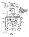
- Wheels 100, 101 are driven by an engine (not shown) through an input or drive shaft 104, a differential mechanism 106, and respective half-axles 108 and 110.
- a steering mechanism 111 is coupled to steerable wheels (not shown) of the vehicle.
- the drive system is conventional and no further details need be disclosed for an understanding of the present invention.
- the wheels 100, 101 are stopped by spring engaged parking brake pistons, or by hydraulically engaged service brake pistons, of brake mechanisms 112,114.
- the brakes are spring biased in the engaged position and are maintained in the disengaged position by application of fluid pressure, as disclosed in our US-A-3,927,737.
- the service brakes are normally actuated via a service brake line 137 connected to the service brake and retarder master cylinders (not shown).
- the service brake system is well-known and does not form a part of this invention.
- the brakes are also actuated through the parking brake lines 136, 138 as described in detail below.
- Means 115 produces a slip signal having a value responsive to the difference in rotational velocity between the wheels 100, 101.
- the slip signal producing means 115 includes a left wheel speed pick up in the form of an electromagnetic transducer 116 which provides pulses in cooperation with a gear-like device 118.
- the device 118 is mounted on and rotates with the axle portion 108. Signals from the transducer 116 are applied to one input of an electronic controller 120, the details of which are described below.
- right wheel signals are provided by a transducer 122 operated in conjunction with a gear-like device 124 which rotates with the axle portion 110. Signals from the transducer 122 are applied to another input of the electronic controller 120.
- Each of the transducers 116, 122 produce respective signals having values responsive to the rotational speed or velocity of the wheels 100, 102. Additionally, a drive shaft speed signal is produced by a transducer 126 in conjunction with a gear-like device 128 which rotates with the drive shaft 104. The drive shaft speed signals are applied to a third input of the electronic controller 120.
- Each of the transducers 116,122,126 is preferably an electromagnetic device which produces a pulse type, time variable output voltage. Such transducers are well-known in the art. However, other transducers, such as optical and Hall effect devices, may be employed as alternatives.
- Means 127 for producing a test signal is also connected to an input of the electronic controller 120. The test signal producing means 127 is preferably a manual switch 129.
- the electronic controller 120 is part of a processor means 121 for receiving the slip signal and producing a brake control signal in response to the slip signal value exceeding a compared reference value.
- a means 131 receives the brake control signal and controllably operates the braking mechanisms 112, 114 in response to the received brake control signal.
- a second embodiment of the present invention includes means 113 for producing a steer signal in response to the position of the steering mechanism 111.
- the steer signal is delivered to the controller 120.
- Means 113 preferably includes a potentiometer 115 controllably connected to the steering mechanism 111.
- the output of the potentiometer 115 is a signal having a value that varies over a negative to positive voltage range, in response to the position of the steering mechanism 111.
- Other suitable angular position transducers may be substituted for the potentiometer 115 in the means 113, as is well-known in the art.
- the controller 120 operates upon the signal inputs, determines the existence, magnitude, and location of wheel slip during a loss of traction situation, and distinguishes between true wheel slip and a transducer failure.
- the power transfer between the two differentially driven wheels 100, 102 is balanced by applying a proportional braking force to the wheel which loses traction. This is accomplished by means of Icoating selection valve 130 and proportioning valve 132, both of which are included in the means 131.
- the valves 130, 132 operate in combination with a supply 134 of oil or brake fluid under pressure, the fluid lines from supply 134 running both through and around the proportioning valve 132 to the solenoid operated selection valve 130 which directs full pressure to one of the brake mechanisms 112, 114, and modulated or proportionally controlled pressure to the other of the brakes 112, 114.
- brake pressure is the inverse of fluid pressure and is applied by relieving the fluid pressure in one of the two brake lines 136, 138, and could be straightforwardly implemented in the opposite fashion, increasing brake pressure in direct rather than inverse ratio to the applied fluid pressure.
- Fig. 2 is a block diagram of the preferred implementation of the anti-spin apparatus described above.
- a solid state digital microprocessor 142 performs system control functions.
- the microprocessor 142 is programmed to establish a plurality of slip value bands, each band having associated therewith an applied brake force value expressed in terms of fluid pressure.
- the microprocessor 142 is interconnected with a band value memory 144 and a timer 146.
- Transducers 116,122,126 are connected to the microprocesor 142 through an input conditioning circuit 140.
- the input circuit 140 provides appropriately digitized input signals to the microprocessor 142.
- Retard brake pressure and service brake pressure switches 148, 150 are likewise connected through an input conditioning circuit 152 to the microprocessor 142.
- the test signal producing means 127 is also connected to the microprocessor 142 through the input circuit 152.
- the steer signal producing means 113 is connected to the microprocessor 142 through the input circuit 152.
- a first output of the microprocessor 142 is connected through a pulse-width modulated servo valve driver 154 to the servo operated proportioning valve 132.
- a second output from the microprocessor 142 is connected to the solenoid driver 133 associated with a left direction selection valve 130a, and a third output from the microprocessor 142 is connected through the solenoid driver 136 to a right direction shuttle valve 230b.
- the pulse width modulated servo valve driver 154 proportionally controls the servo valve 132, in a manner well-known in the art. Therefore, adverting momentarily to Fig. 1, fluid pressure is modulated via the proportioning valve 132 to the brake line 136, 138 selected by the position of the valve 130.
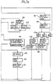
- a functional flowchart defining the internal programming for the microprocessor 142 is shown. From this flowchart, a programmer of ordinary skill can develop a specific set of program instructions for a general purpose microprocessor that defines the necessary slip signal value bands, timing cycles, and brake fluid pressure values necessary for implementation of the instant invention. It will be appreciated that, while the best mode of the invention is considered to comprise a properly programmed microprocessor 142, the result of which is the creation of novel hardware associations within the microprocessor 142 and its associated devices, it is possible to implement the instant invention utilizing traditional hard wired circuits.
- Data delivered by the transducers 116, 122 is sampled in block 164 of Fig. 3.
- control progresses along the right side of the flow diagram to block 166.
- the input shaft speed is determined in block 166, and is compared in block 168 with the non-zero wheel velocity. If the ratio of the non-zero wheel velocity to drive shaft speed is equal to or less than a constant, for example, 1.5, it is assumed that the wheel indicating zero speed is actually turning and that the zero indication is the result of a failed transducer. In this case, the program returns to the original starting point and, if desired, an indication of the apparent transducer failure can be presented to the operator.
- the value of the constant selected is determined according to the gear ratio of the differential mechanism 106. As a matter of convenience for purposes of this discussion, a differential ratio of 1:1 is assumed throughout.
- the program progresses to blocks 170a, b, c. 1f one of the wheel velocities is not zero, the program progresses to blocks 172a, b, which is an event counter requiring several successive cycles of the above conditions prior to activation of the anti-spin apparatus. This delay filters out short term wheel speed aberations and has been found to be advantageous for efficient system operation. If the event counter has not incremented or counted a sufficient number of cycles, the program progress to blocks 174, b which increment the counter. The program then returns to the original starting point.
- the program progresses to block 176.
- block 170c advances the program to blocks 178, 180, 182, 184, releasing the parking brake 112, 114 and resetting the timer 146. The same result occurs if automatic control is contra-indicated in block 176.
- Block 176 the program progresses to block 186 to determine whether the slip control system is activated. If so, the effect is the same as entering band 5, the most severe slip condition band, and control passes to block 194.
- Block 194 increases the wheel brake force by decreasing the wheel brake hold off pressure by an increment X, for each timed interval established by the microprocessor timer 146. If the slip control system is not operative in block 186, the program progresses to block 188 which activates the system, and then through blocks 190 and 192 to begin the timing cycle and reduce the brake hold off pressure to a value just sufficient to maintain the brakes in the released position.
- block 196 determines the location of the actual slip signal value within one of five slip bands represented by Table 1.
- the slip bands are contiguous, the upper limit of one band being the lower limit of the next, with the highest slip value being the first predetermined reference value referred to above.
- the first predetermined reference value must be exceeded by the slip control signal value before anti-slip control begins.
- the processor means 121 makes this determination by comparing the slip signal value with the first predetermined reference value, and with the other reference values shown in Table 1.
- the first reference value must be established higher than the maximum slip signal value produced by steering the vehicle in a hard cornering maneuver. This value varies according to the design of the vehicle. As shown in Table 1, for purposes of this discussion, a value of 1.7 is considered to be greater than the maximum slip signal value produced by steering the vehicle.
- program blocks 198, 200, 202 represent the determination of which of the wheels is rotating at a higher velocity, and the disposition of the valve 130 to direct modulated brake fluid pressure to the highest velocity wheel and unmodulated brake fluid pressure to the lower velocity wheel (remembering the inverse relationship between brake pressure and brake fluid pressure).
- the program then advances to block 204 and determines whether a sufficient slip time period has elapsed to begin operation of the control system. If insufficient time has elapsed, program block 206 increments a counter and the program advances to the starting point. If sufficient time has elapsed, the program advances to block 208 in which the various signal conditions which might contra-indicate operation of the slip control system are considered.
- the program advances to the appropriate one of the blocks 210, 212, 214, 216, 218, as determined in block 196.
- the vehicle can enter the slip control mode only via band 5. Therefore, the slip value must exceed the first predetermined reference value, for example, 1.7. This prevents unintentional activation of the control system while steering the vehicle.
- the control mode Once the control mode has been entered through band 5, control is excited by sequencing through the lower bands 4-1, producing a smooth transition back to the uncontrolled mode.
- the brake force is periodically incremented in block 194 by reducing the brake pressure by the increment X for every timing cycle, until the slip signal value causes entry into another slip band.
- the first step from the hold off pressure of 400 psi represents an abrupt reduction in pressure to 200 psi, followed by three additional incremental reductions of approximately 33 psi each, increasing the parking brake force through spring action with each incremental step.
- Blocks 220, 222 cause the brake force to be increased by a smaller increment Y for every timing cycle. Accordingly, the system approaches the full brake force condition in a gradual curve, with the. brake force increments becoming smaller toward the full brake force condition.
- band 3 is the mirror image of band 4, and causes incremental reductions in braking force through incremental increases in brake fluid pressure.
- Band 2 is the mirror image of band 5, and causes large incremental reductions in brake force.
- Band 1 has no counterpart, and causes still larger reductions in brake force as represented by the increment W in the diagram of Fig. 4.
- the anti-spin apparatus operates to detect a slipping wheel, to apply braking force to the slipping wheel, and to periodically and incrementally modulate the brake force either positively or negatively in accordance with the degree of slip which is detected by the system.
- Conditions giving rise to a slip signal value of 1.7 or less do not cause entry into the slip control mode, because the first predetermined reference value is not exceeded. This prevents unintentional operation of the anti-spin control owing to steering of the vehicle.
- actual slip that does not exceed the first predetermined reference value is likewise not corrected for by the control system.
- the test signal producing means 127 When the test switch 129 is moved from the "normal" to the "test” position, the first predetermined reference value is replaced by a second predetermined reference value. For example, as is shown in Table 1, the reference value required to enter slip band 5 is reduced from the first value of 1.7 to the second or modified value of 1.25. Band values 4-1 are likewise reduced. These are the values stored in the band value memory 144 and utilized in the calculation of block 196. Therefore, in response to selecting the "test" mode, the processor means 121 receives the slip signal and the test signal and compares the slip signal with the second predetermined reference value. Anti-slip control is thus initiated in response to a slip signal value less than the slip signal produced by steering the vehicle. This produces two important results.
- the operator can readily determine whether or not the anti-spin apparatus is functioning properly by merely steering the vehicle into a hard turn. If the slip control is operating properly, the operator can observe the application of the vehicle brake 112, 114 to the radially outer of the differentially driven wheels 100, 101, in response to the slip signal value produced by steering the vehicle exceeding the modified threshold value. Thus, it is relatively easy for the operator to determine the operability of the control system prior to encountering a low traction situation.
- the alternative embodiment of the anti-spin apparatus in which the steer signal producing means 113 is included, as shown within the dotted area of Fig. 3, is a further enhancement of the control system.
- the processor means 121 receives the steer signal and controllably modifies the slip signal values in response to the value of the steer signal, in the absence of the test signal. Assuming that the test switch 129 is in the "normal" position, and that neither wheel velocity is found to be zero in block 164, program control progresses to block 250, in which a slip value is calculated as S c .
- the sign of So is determined in the blocks 252, 254, 256. If the right wheel is the faster of the two wheels, the quantity So is positive, and if the right wheel is not the faster of the two wheels, the quantity So is negative. So is next delivered to block 262.
- the inverted steer signal value S s is delivered from the block 260, and also supplied to the block 262.
- the signals So and S s are summed and delivered to the block 196, in which the appropriate slip band is calculated and control progresses as described above.
- the slip band reference or threshold values utilized by the control system are much lower as applied to the instant embodiment of the invention, than the values utilized in the embodiment having no steer input signal.
- the steer signal producing means 113 supplies a positive signal to block 260 in response to steering the vehicle in a left turn, and a negative signal in response to steering the vehicle in a right turn.
- the left or radially outer wheels 100, 101 rotate at a higher velocity than do the right or radially inner wheels.
- So is calculated in block 250 and negative So is delivered from block 254 to block 262.
- the steer signal polarity is inverted in block 260 and the signal is delivered as a positive signal to block 262, effectively cancelling the false slip signal caused by turning the vehicle, thus preventing entry into the control mode.
- the processor means 121 accomplishes the same result as that just described, by continuously modifying the band threshold values in response to receiving the steer signal in the absence of the test signal.
- the first predetermined reference value is continuously maintained a predetermined amount greater than the actual slip signal value produced in response to steering the vehicle.
- Adding the steer signal producing means 113 to the anti-spin control system accounts for differences in wheel velocity caused solely by steering the vehicle, and prevents such wheel velocity differences from appearing to the control as an actual slip condition. By negating the effect of steering on operation of the control, the anti-spin system is made extremely sensitive to small slip conditions that prior systems are unable to automatically contend with. Keeping the above principles in mind, and having the flexibility of a programmable microprocessor, one skilled in the art can produce other related methods of accomplishing this same result.
- the anti-spin control system can be tested by steering the vehicle in a hard turn while the test signal producing means 127 is in the "test" mode.
- control mode will never be entered solely in response to steering the vehicle.
Landscapes
- Engineering & Computer Science (AREA)
- Transportation (AREA)
- Mechanical Engineering (AREA)
- Physics & Mathematics (AREA)
- Fluid Mechanics (AREA)
- Chemical & Material Sciences (AREA)
- Combustion & Propulsion (AREA)
- Regulating Braking Force (AREA)
Applications Claiming Priority (2)
| Application Number | Priority Date | Filing Date | Title |
|---|---|---|---|
| US06/605,757 US4521856A (en) | 1984-05-01 | 1984-05-01 | Multiple threshold wheel slip control apparatus and method |
| US605757 | 1984-05-01 |
Publications (3)
| Publication Number | Publication Date |
|---|---|
| EP0179066A1 EP0179066A1 (en) | 1986-04-30 |
| EP0179066A4 EP0179066A4 (en) | 1987-01-20 |
| EP0179066B1 true EP0179066B1 (en) | 1989-05-03 |
Family
ID=24425093
Family Applications (1)
| Application Number | Title | Priority Date | Filing Date |
|---|---|---|---|
| EP84902886A Expired EP0179066B1 (en) | 1984-05-01 | 1984-07-12 | Multiple threshold wheel slip control apparatus and method |
Country Status (9)
| Country | Link |
|---|---|
| US (1) | US4521856A (ja) |
| EP (1) | EP0179066B1 (ja) |
| JP (1) | JPH0671879B2 (ja) |
| AU (1) | AU560648B2 (ja) |
| BR (1) | BR8407310A (ja) |
| DE (1) | DE3478009D1 (ja) |
| SG (1) | SG6592G (ja) |
| WO (1) | WO1985005083A1 (ja) |
| ZA (1) | ZA852956B (ja) |
Cited By (1)
| Publication number | Priority date | Publication date | Assignee | Title |
|---|---|---|---|---|
| EP1527939A1 (de) | 1999-11-24 | 2005-05-04 | Bosch Rexroth AG | Hydrostatischer Fahrantrieb und Verfahren zum Betreiben des hydrostatischen Fahrantriebs |
Families Citing this family (38)
| Publication number | Priority date | Publication date | Assignee | Title |
|---|---|---|---|---|
| DE3508879A1 (de) * | 1985-03-13 | 1986-09-25 | Zahnräderfabrik Renk AG, 8900 Augsburg | Steuerschaltung fuer kraftfahrzeuge |
| JPS61283736A (ja) * | 1985-06-08 | 1986-12-13 | Toyota Motor Corp | 車両スリツプ制御装置 |
| JPH0624908B2 (ja) * | 1985-11-25 | 1994-04-06 | トヨタ自動車株式会社 | 鳴き防止機能を有する車両用ブレ−キシステム |
| CA1312129C (en) * | 1986-03-04 | 1992-12-29 | Honda Giken Kogyo Kabushiki Kaisha (Also Trading As Honda Motor Co., Ltd .) | Traction control system for controlling slip of a driving wheel of a vehicle |
| US4745552A (en) * | 1986-03-31 | 1988-05-17 | Caterpillar Inc. | Anti-spin control apparatus and method |
| US4840247A (en) * | 1986-05-06 | 1989-06-20 | Toyota Jidosha Kabushiki Kaisha | Device for controlling 4wd vehicle central differential restriction device according to front and rear wheels rotational speed difference, and method of operation thereof |
| US4873638A (en) * | 1986-05-09 | 1989-10-10 | Honda Giken Kogyo Kabushiki Kaisha | Traction control system for controlling slip of a driving wheel of a vehicle |
| CA1306784C (en) * | 1986-06-09 | 1992-08-25 | Masakazu Sakaguchi | Method for controlling slip of a driving wheel of a vehicle |
| AT394685B (de) * | 1986-07-01 | 1992-05-25 | Steyr Daimler Puch Ag | Antriebsanordnung fuer ein kraftfahrzeug |
| US4718303A (en) * | 1986-10-06 | 1988-01-12 | Borg-Warner Automotive, Inc. | Four wheel drive transfer case with clutch mechanism |
| US4750125A (en) * | 1986-10-10 | 1988-06-07 | General Motors Corporation | Vehicle wheel slip control system |
| DE3718421A1 (de) * | 1987-06-02 | 1988-12-15 | Teves Gmbh Alfred | Schaltungsanordnung fuer bremsanlagen mit blockierschutz- und/oder antriebsschlupf-regelung |
| DE3726998C2 (de) * | 1987-08-13 | 1995-07-06 | Teves Gmbh Alfred | Verfahren und Schaltungsanordnung zur Regelung des Radschlupfes mit einer elektronisch steuerbaren Kraftfahrzeug-Bremsanlage |
| DE3816039A1 (de) * | 1988-05-10 | 1989-11-23 | Lucas Ind Plc | Verfahren zum ueberwachen der funktionstuechtigkeit von drehzahlsensoren |
| JP2832605B2 (ja) * | 1988-06-27 | 1998-12-09 | 本田技研工業株式会社 | 車両の駆動輪制動制御方法および装置 |
| DE3877757D1 (de) * | 1988-10-13 | 1993-03-04 | Siemens Ag | Verfahren zur unterscheidung durchdrehender raeder eines fahrzeuges von triebstrangschwingungen. |
| DE3837862C2 (de) * | 1988-11-08 | 1993-09-30 | Gkn Automotive Ag | Vorrichtung zur Steuerung von Sperrdifferentialen |
| US5079708A (en) * | 1989-03-24 | 1992-01-07 | Brown Jack L | Road vehicle cornering assistance mechanism |
| US5357444A (en) * | 1990-02-28 | 1994-10-18 | Aisin Seiki Kabushiki Kaisha | Retarding control apparatus which operates on the basis of signals such as a shift lever position signal |
| DE4018495C2 (de) * | 1990-06-09 | 2000-08-03 | Continental Teves Ag & Co Ohg | Schaltungsanordnung zur Verbesserung des Fahrverhaltens eines zur Übersteuerung neigenden Kraftfahrzeuges |
| JP2623927B2 (ja) * | 1990-07-05 | 1997-06-25 | 日産自動車株式会社 | 車両の旋回挙動制御装置 |
| US5205622A (en) * | 1991-02-08 | 1993-04-27 | Eaton Corporation | Vehicular traction control system |
| JP3207462B2 (ja) * | 1991-09-13 | 2001-09-10 | マツダ株式会社 | 車両のアンチスキッドブレーキ装置 |
| WO1993007037A1 (en) * | 1991-10-04 | 1993-04-15 | Caterpillar Inc. | Method and apparatus for controlling differentially driven wheel slip for an articulated vehicle |
| USRE36152E (en) * | 1991-10-04 | 1999-03-16 | Caterpillar Inc. | Method and apparatus for controlling differentially driven wheel-slip for an articulated machine |
| US5535124A (en) * | 1991-10-04 | 1996-07-09 | Caterpillar Inc. | Method and apparatus for controlling differentially driven wheel-slip for an articulated machine |
| JP2591710B2 (ja) * | 1994-05-02 | 1997-03-19 | 一 野口 | 格子止め金具 |
| US5810095A (en) * | 1996-07-25 | 1998-09-22 | Case Corporation | System for controlling the position of an implement attached to a work vehicle |
| JP4120504B2 (ja) * | 2003-07-30 | 2008-07-16 | トヨタ自動車株式会社 | 車両および車両の制御方法 |
| JP4239725B2 (ja) * | 2003-07-30 | 2009-03-18 | トヨタ自動車株式会社 | 車両および車両の制御方法 |
| US7500687B2 (en) * | 2004-01-31 | 2009-03-10 | Lockheed Martin Corporation | Vehicle suspension systems |
| US7393065B2 (en) * | 2006-06-01 | 2008-07-01 | Lockheed Martin Corporation | Redundant braking system |
| US20080066613A1 (en) * | 2006-09-15 | 2008-03-20 | Lockheed Martin Corporation | Perforated hull for vehicle blast shield |
| US20080173167A1 (en) * | 2006-09-15 | 2008-07-24 | Armor Holdings | Vehicular based mine blast energy mitigation structure |
| US7894958B2 (en) | 2008-02-11 | 2011-02-22 | Caterpillar Inc | Traction control system |
| US8626404B2 (en) | 2010-11-19 | 2014-01-07 | Caterpillar Inc. | Motor grader wheel slip control for cut to grade |
| US9849782B2 (en) | 2012-05-22 | 2017-12-26 | Caterpillar Inc. | Hydraulic motor having controlled output based on machine slippage model |
| US9214273B2 (en) * | 2013-06-11 | 2015-12-15 | Abb Technology Ag | Radial drop winding for open-wound medium voltage dry type transformers with improved support structure |
Family Cites Families (16)
| Publication number | Priority date | Publication date | Assignee | Title |
|---|---|---|---|---|
| US30763A (en) * | 1860-11-27 | Improvement in cotton-cultivators | ||
| US3825306A (en) * | 1970-10-07 | 1974-07-23 | Itt | Differential-lock type device for a motor vehicle |
| DE2063944C3 (de) * | 1970-12-28 | 1982-03-11 | Teldix Gmbh, 6900 Heidelberg | Schaltungsanordnung einer blockiergeschützten Fahrzeugbremsanlage |
| DE2148302A1 (de) * | 1971-09-28 | 1973-04-05 | Daimler Benz Ag | Vorrichtung zum verhueten des durchdrehens der angetriebenen raeder eines fahrzeuges |
| JPS5241436B2 (ja) * | 1972-11-10 | 1977-10-18 | ||
| US4042059A (en) * | 1973-05-21 | 1977-08-16 | Kelsey-Hayes Company | Anti-spin control system |
| DE2558712A1 (de) * | 1975-12-24 | 1977-07-14 | Teldix Gmbh | Antiblockierregelsystem |
| US4066300A (en) * | 1976-10-29 | 1978-01-03 | Aspro, Inc. | Digital traction control system |
| GB2016101B (en) * | 1978-01-18 | 1982-04-07 | Honda Motor Co Ltd | Anti wheel lock method preventing wheel lock |
| AT390416B (de) * | 1978-04-28 | 1990-05-10 | Wabco Fahrzeugbremsen Gmbh | Anordnung zum verhindern des durchdrehens eines oder mehrerer angetriebener raeder, insbesondere beim anfahren |
| US4361871A (en) * | 1980-05-07 | 1982-11-30 | Caterpillar Tractor Co. | Failsafe wheel slip control system and method of operating same |
| EP0054029B2 (en) * | 1980-05-07 | 1990-06-06 | Caterpillar Inc. | Method and apparatus for controlling differentially driven wheel slip |
| US4395761A (en) * | 1980-05-15 | 1983-07-26 | Honda Giken Kogyo Kabushiki Kaisha | Antiskid brake controlling method and apparatus for vehicles |
| DE3152999C2 (ja) * | 1980-08-25 | 1991-04-18 | Honda Giken Kogyo K.K., Tokio/Tokyo, Jp | |
| JPS5820051A (ja) * | 1981-07-29 | 1983-02-05 | Toshiba Corp | 論理レベル判定回路 |
| DE3234282A1 (de) * | 1982-09-16 | 1984-03-22 | Robert Bosch Gmbh, 7000 Stuttgart | Vorrichtung zum steuern der drehzahlen der angetriebenen raeder eines kraftfahrzeuges |
-
1984
- 1984-05-01 US US06/605,757 patent/US4521856A/en not_active Expired - Lifetime
- 1984-07-12 WO PCT/US1984/001120 patent/WO1985005083A1/en active IP Right Grant
- 1984-07-12 AU AU31551/84A patent/AU560648B2/en not_active Ceased
- 1984-07-12 BR BR8407310A patent/BR8407310A/pt not_active IP Right Cessation
- 1984-07-12 DE DE8484902886T patent/DE3478009D1/de not_active Expired
- 1984-07-12 JP JP59502786A patent/JPH0671879B2/ja not_active Expired - Fee Related
- 1984-07-12 EP EP84902886A patent/EP0179066B1/en not_active Expired
-
1985
- 1985-04-19 ZA ZA852956A patent/ZA852956B/xx unknown
-
1992
- 1992-01-24 SG SG65/92A patent/SG6592G/en unknown
Cited By (2)
| Publication number | Priority date | Publication date | Assignee | Title |
|---|---|---|---|---|
| EP1527939A1 (de) | 1999-11-24 | 2005-05-04 | Bosch Rexroth AG | Hydrostatischer Fahrantrieb und Verfahren zum Betreiben des hydrostatischen Fahrantriebs |
| EP1527939B2 (de) † | 1999-11-24 | 2009-07-29 | Bosch Rexroth AG | Hydrostatischer Fahrantrieb und Verfahren zum Betreiben des hydrostatischen Fahrantriebs |
Also Published As
| Publication number | Publication date |
|---|---|
| ZA852956B (en) | 1985-12-24 |
| WO1985005083A1 (en) | 1985-11-21 |
| AU560648B2 (en) | 1987-04-09 |
| JPS61501974A (ja) | 1986-09-11 |
| DE3478009D1 (en) | 1989-06-08 |
| EP0179066A4 (en) | 1987-01-20 |
| US4521856A (en) | 1985-06-04 |
| SG6592G (en) | 1992-03-20 |
| JPH0671879B2 (ja) | 1994-09-14 |
| AU3155184A (en) | 1985-11-28 |
| EP0179066A1 (en) | 1986-04-30 |
| BR8407310A (pt) | 1986-04-15 |
Similar Documents
| Publication | Publication Date | Title |
|---|---|---|
| EP0179066B1 (en) | Multiple threshold wheel slip control apparatus and method | |
| US5535124A (en) | Method and apparatus for controlling differentially driven wheel-slip for an articulated machine | |
| DE3913052C2 (de) | Antriebsschlupfregelung | |
| JP3095076B2 (ja) | 車両のトラクションコントロール装置 | |
| EP0736428A1 (en) | Vehicle attitude control system having vehicle decelerating device operated before operation of vehicle attitude control device | |
| US5014202A (en) | Vehicle traction control system | |
| US4511971A (en) | Antilocking brake system | |
| US4745552A (en) | Anti-spin control apparatus and method | |
| US5193888A (en) | Slip control system for motor vehicle | |
| USRE36152E (en) | Method and apparatus for controlling differentially driven wheel-slip for an articulated machine | |
| US5205622A (en) | Vehicular traction control system | |
| US5685619A (en) | Energy management method for a traction control system | |
| CA1217545A (en) | Multiple threshold wheel slip control apparatus and method | |
| KR950014359B1 (ko) | 차량의 미끄럼방지 브레이크 장치 | |
| EP0051601B1 (en) | Failsafe wheel slip control system and method of operating same | |
| EP0605559B1 (en) | Method and apparatus for controlling differentially driven wheel slip for an articulated vehicle | |
| US5542756A (en) | Reduced brake switch dependence control method and system for vehicle anti-lock brake system | |
| JP2629446B2 (ja) | 車両のトラクションコントロール装置 | |
| JPH044925Y2 (ja) | ||
| JPS6050061A (ja) | アンチスキッド制御方法 | |
| JPH0447015Y2 (ja) | ||
| JP3758352B2 (ja) | 車両挙動制御装置 | |
| JPH044924Y2 (ja) | ||
| JPS6171265A (ja) | アンチスキツド制御方法 | |
| JPH0439789Y2 (ja) |
Legal Events
| Date | Code | Title | Description |
|---|---|---|---|
| PUAI | Public reference made under article 153(3) epc to a published international application that has entered the european phase |
Free format text: ORIGINAL CODE: 0009012 |
|
| 17P | Request for examination filed |
Effective date: 19860117 |
|
| AK | Designated contracting states |
Kind code of ref document: A1 Designated state(s): DE FR GB SE |
|
| RAP1 | Party data changed (applicant data changed or rights of an application transferred) |
Owner name: CATERPILLAR INC. |
|
| A4 | Supplementary search report drawn up and despatched |
Effective date: 19870120 |
|
| 17Q | First examination report despatched |
Effective date: 19871202 |
|
| GRAA | (expected) grant |
Free format text: ORIGINAL CODE: 0009210 |
|
| AK | Designated contracting states |
Kind code of ref document: B1 Designated state(s): DE FR GB SE |
|
| REF | Corresponds to: |
Ref document number: 3478009 Country of ref document: DE Date of ref document: 19890608 |
|
| ET | Fr: translation filed | ||
| PLBE | No opposition filed within time limit |
Free format text: ORIGINAL CODE: 0009261 |
|
| STAA | Information on the status of an ep patent application or granted ep patent |
Free format text: STATUS: NO OPPOSITION FILED WITHIN TIME LIMIT |
|
| 26N | No opposition filed | ||
| EAL | Se: european patent in force in sweden |
Ref document number: 84902886.5 |
|
| PGFP | Annual fee paid to national office [announced via postgrant information from national office to epo] |
Ref country code: FR Payment date: 19950525 Year of fee payment: 12 |
|
| PG25 | Lapsed in a contracting state [announced via postgrant information from national office to epo] |
Ref country code: FR Effective date: 19970328 |
|
| REG | Reference to a national code |
Ref country code: FR Ref legal event code: ST |
|
| PGFP | Annual fee paid to national office [announced via postgrant information from national office to epo] |
Ref country code: SE Payment date: 19970617 Year of fee payment: 14 |
|
| PG25 | Lapsed in a contracting state [announced via postgrant information from national office to epo] |
Ref country code: SE Free format text: LAPSE BECAUSE OF NON-PAYMENT OF DUE FEES Effective date: 19980713 |
|
| EUG | Se: european patent has lapsed |
Ref document number: 84902886.5 |
|
| REG | Reference to a national code |
Ref country code: GB Ref legal event code: IF02 |
|
| PGFP | Annual fee paid to national office [announced via postgrant information from national office to epo] |
Ref country code: GB Payment date: 20020613 Year of fee payment: 19 |
|
| PGFP | Annual fee paid to national office [announced via postgrant information from national office to epo] |
Ref country code: DE Payment date: 20020731 Year of fee payment: 19 |
|
| PG25 | Lapsed in a contracting state [announced via postgrant information from national office to epo] |
Ref country code: GB Free format text: LAPSE BECAUSE OF NON-PAYMENT OF DUE FEES Effective date: 20030712 |
|
| PG25 | Lapsed in a contracting state [announced via postgrant information from national office to epo] |
Ref country code: DE Free format text: LAPSE BECAUSE OF NON-PAYMENT OF DUE FEES Effective date: 20040203 |
|
| GBPC | Gb: european patent ceased through non-payment of renewal fee |
Effective date: 20030712 |