EP0176758B1 - Fluidtransportraupe - Google Patents
Fluidtransportraupe Download PDFInfo
- Publication number
- EP0176758B1 EP0176758B1 EP85110729A EP85110729A EP0176758B1 EP 0176758 B1 EP0176758 B1 EP 0176758B1 EP 85110729 A EP85110729 A EP 85110729A EP 85110729 A EP85110729 A EP 85110729A EP 0176758 B1 EP0176758 B1 EP 0176758B1
- Authority
- EP
- European Patent Office
- Prior art keywords
- stator
- caterpillar
- fluid
- pressure
- belt
- Prior art date
- Legal status (The legal status is an assumption and is not a legal conclusion. Google has not performed a legal analysis and makes no representation as to the accuracy of the status listed.)
- Expired
Links
- 239000012530 fluid Substances 0.000 title claims abstract description 44
- 210000004027 cell Anatomy 0.000 claims description 29
- 230000002706 hydrostatic effect Effects 0.000 claims description 21
- 210000002421 cell wall Anatomy 0.000 claims description 8
- 239000012791 sliding layer Substances 0.000 claims description 6
- 239000000839 emulsion Substances 0.000 claims description 3
- 230000002787 reinforcement Effects 0.000 claims description 3
- XLYOFNOQVPJJNP-UHFFFAOYSA-N water Substances O XLYOFNOQVPJJNP-UHFFFAOYSA-N 0.000 claims description 3
- 210000003850 cellular structure Anatomy 0.000 claims description 2
- 239000010410 layer Substances 0.000 claims description 2
- 239000010720 hydraulic oil Substances 0.000 claims 1
- 239000007788 liquid Substances 0.000 claims 1
- 230000032258 transport Effects 0.000 description 18
- 238000010276 construction Methods 0.000 description 4
- 239000000463 material Substances 0.000 description 3
- 238000011161 development Methods 0.000 description 2
- 230000018109 developmental process Effects 0.000 description 2
- 239000013013 elastic material Substances 0.000 description 2
- 239000003921 oil Substances 0.000 description 2
- 238000007789 sealing Methods 0.000 description 2
- 229910000831 Steel Inorganic materials 0.000 description 1
- 230000000712 assembly Effects 0.000 description 1
- 238000000429 assembly Methods 0.000 description 1
- 238000005452 bending Methods 0.000 description 1
- 230000005540 biological transmission Effects 0.000 description 1
- 230000001419 dependent effect Effects 0.000 description 1
- 238000006073 displacement reaction Methods 0.000 description 1
- 230000000694 effects Effects 0.000 description 1
- 238000005265 energy consumption Methods 0.000 description 1
- 238000005516 engineering process Methods 0.000 description 1
- 230000035945 sensitivity Effects 0.000 description 1
- 239000007787 solid Substances 0.000 description 1
- 239000010959 steel Substances 0.000 description 1
Images


Classifications
-
- B—PERFORMING OPERATIONS; TRANSPORTING
- B62—LAND VEHICLES FOR TRAVELLING OTHERWISE THAN ON RAILS
- B62D—MOTOR VEHICLES; TRAILERS
- B62D55/00—Endless track vehicles
- B62D55/06—Endless track vehicles with tracks without ground wheels
- B62D55/062—Tracked vehicles of great dimensions adapted for moving bulky loads or gear
-
- B—PERFORMING OPERATIONS; TRANSPORTING
- B62—LAND VEHICLES FOR TRAVELLING OTHERWISE THAN ON RAILS
- B62D—MOTOR VEHICLES; TRAILERS
- B62D55/00—Endless track vehicles
- B62D55/08—Endless track units; Parts thereof
- B62D55/18—Tracks
- B62D55/24—Tracks of continuously flexible type, e.g. rubber belts
- B62D55/247—Gas filled or inflatable flexible tracks
Definitions
- crawler tracks The uniform design principle of these crawler tracks is the multiple arrangement of carrying wheels, running wheels and drive wheels, over which a track chain stretched out of links is endlessly laid. This converts the wheel-related high ground pressure into a load-distributing low surface pressure.
- the running and support wheels roll on the caterpillar track and move the vehicle forward.
- the air cushion loaded by the caterpillar belt according to known devices is not technically manageable for higher lateral forces from transverse drift and steering lock.
- the required sensitivity for the air cushion is also insufficient due to the crawler belt, which is broken up into link elements, when the floor is uneven, and the effect of the air cushion is disturbed.
- a transport vehicle according to the description of the invention FR-A-2149 388 is known, which is moved on a crawler track with a rubber-like caterpillar belt.
- the crawler undercarriage is arranged in such a way that it encloses the base area of the vehicle in an airtight and pressure-tight manner and leaves a space open to the floor area in which an air cushion can be built up.
- the air cushion is supported against the support plate of the vehicle, against the roadway and against the crawler chassis enclosing the air cushion on all sides.
- This transport vehicle requires a stable, completely smooth and level road.
- the horizontal movement is carried out by additional pulling and braking devices.
- the technical problem that is to be solved with the invention is to create a caterpillar vehicle with an elastic carcass and fluidic support system without a wheel support device and with the advantages of small dimensions, low construction mass and hermetically sealed construction.
- the caterpillar vehicle should be independently drivable and maneuverable without the use of slideways or special pretreatment of the transport route.
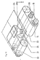
- the object is achieved by the development of a fluid transport caterpillar in that an endless, flexible, liquid- and pressure-tight caterpillar belt is stretched over its entire width via a stator which is resistant to bending and use and whose basic shape corresponds to a caterpillar body.
- This stator contains pressure-tight cells as pressure vessels for the fluid. Channels that lead from these cells to the lower outer surface of the stator are distributed uniformly over the width of the stator.
- a collecting tray for the fluid is arranged centrally in the stator, which is connected via an opening to the upper outer surface of the stator and via a pipe system to the pressure-tight cells.
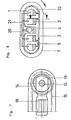
- the stator is closed on both sides in a pressure-tight manner by side walls which protrude so far that a seal can be made between them and the crawler belt.
- the surface of the caterpillar belt facing the stator has a structure of cells which are open to the outside and have elastic cell walls.
- the crawler belt contains known non-rigid reinforcements, which are supported and guided against the all-sided projecting side walls of the stator by supporting bodies which protrude on both sides at an equal distance and the same length and thus form a roller chain.
- roller chains which are arranged on both sides, are non-positively guided via wheel disks, which rest on the outside of the stator in the deflection points of the crawler belt on both sides, driven in a known manner by a drive unit, but are not involved in the load-bearing behavior.
- the pressure fluid required for the function of the fluid transport caterpillar is passed through a circulation pump from the centrally arranged collecting trough via pipes into the pressure-tight cells of the stator and further via channels to form the fluid gap between the stator and the caterpillar belt.
- the honeycomb or cup-like hydrostatic cells of the inner sliding layer of the crawler belt is passed through a circulation pump from the centrally arranged collecting trough via pipes into the pressure-tight cells of the stator and further via channels to form the fluid gap between the stator and the caterpillar belt.
- the fluid flowing longitudinally and transversely out of the fluid gap is displaced towards the top of the stator, flows back through a hole into the collecting trough and is returned to the circuit by the circulation pump.
- the load is entered into the center of the stator via movable axes.
- the system can be steered in a known manner.
- Fluid means oils, emulsions or water.
- the ratio of the mass of the means of transport to the mass of the transport object is clearly shifted in favor of the low mass of means of transport.
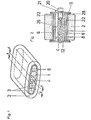
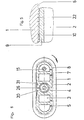
- An endless flexible caterpillar belt 2 with a homogeneous or cellular structure made of rubber-like material is stretched over a stator 1 in the form of the caterpillar body 32.
- the stator 1 as the supporting structure of the device is broken down into pressure-tight cells 3, 4, which are connected to the sliding surface 6 of the stator 1 via channels 5 on the bottom side.
- the channels 5 are distributed over the width of the bottom side of the stator 1. They are concentrated in the two-sided end zones on the bottom side. Fewer channels are arranged in the central area of the base.
- the endless flexible caterpillar hand 2 consists of a wear-resistant and elastic material in its outer layer coming into contact with the bottom surface 7.
- a strength member 8 consisting of inserts of known reinforcements, a steel cable network or a chain belt.
- the strength member 8 is embedded in the elastic material, the insert being arranged near the inner sliding layer 9.
- the sliding layer 9 of the caterpillar belt 2 consists of a structured surface, preferably a honeycomb-shaped or cup-like structure 36, which is broken up into individual cells 10.
- the strength member 8 in the caterpillar belt 2 is supported against the side walls 12 of the stator 1 by means of its metallic support bodies 11 which protrude on both sides.
- this support takes place with a known cage-free roller guide 13.
Landscapes
- Engineering & Computer Science (AREA)
- Chemical & Material Sciences (AREA)
- Combustion & Propulsion (AREA)
- Transportation (AREA)
- Mechanical Engineering (AREA)
- Handcart (AREA)
- Lubricants (AREA)
- Structures Of Non-Positive Displacement Pumps (AREA)
- Structure Of Belt Conveyors (AREA)
- Actuator (AREA)
- Fluid-Pressure Circuits (AREA)
- Vehicle Body Suspensions (AREA)
- Current-Collector Devices For Electrically Propelled Vehicles (AREA)
- Details And Applications Of Rotary Liquid Pumps (AREA)
- Magnetic Bearings And Hydrostatic Bearings (AREA)
- Crystals, And After-Treatments Of Crystals (AREA)
- General Details Of Gearings (AREA)
Priority Applications (1)
| Application Number | Priority Date | Filing Date | Title |
|---|---|---|---|
| AT85110729T ATE40865T1 (de) | 1984-09-05 | 1985-08-27 | Fluidtransportraupe. |
Applications Claiming Priority (2)
| Application Number | Priority Date | Filing Date | Title |
|---|---|---|---|
| DD267122 | 1984-09-05 | ||
| DD84267122A DD241531A3 (de) | 1984-09-05 | 1984-09-05 | Fluidtransportraupe |
Publications (3)
| Publication Number | Publication Date |
|---|---|
| EP0176758A2 EP0176758A2 (de) | 1986-04-09 |
| EP0176758A3 EP0176758A3 (en) | 1987-03-25 |
| EP0176758B1 true EP0176758B1 (de) | 1989-02-22 |
Family
ID=5560313
Family Applications (1)
| Application Number | Title | Priority Date | Filing Date |
|---|---|---|---|
| EP85110729A Expired EP0176758B1 (de) | 1984-09-05 | 1985-08-27 | Fluidtransportraupe |
Country Status (11)
| Country | Link |
|---|---|
| US (1) | US4673050A (enExample) |
| EP (1) | EP0176758B1 (enExample) |
| JP (1) | JPS61119477A (enExample) |
| AT (1) | ATE40865T1 (enExample) |
| AU (1) | AU4712185A (enExample) |
| CA (1) | CA1241045A (enExample) |
| CS (1) | CS595085A1 (enExample) |
| DD (1) | DD241531A3 (enExample) |
| DE (1) | DE3568315D1 (enExample) |
| HU (1) | HU196147B (enExample) |
| SU (1) | SU1438992A1 (enExample) |
Families Citing this family (5)
| Publication number | Priority date | Publication date | Assignee | Title |
|---|---|---|---|---|
| US6186257B1 (en) * | 1999-10-15 | 2001-02-13 | Meritor Heavy Vehicle Systems, Inc. | Method and system for floating a vehicle |
| US6857489B2 (en) | 2000-02-18 | 2005-02-22 | Manitowoc Crane Companies, Inc. | Crawler crane having identical left and right crawler assemblies |
| AU2014202781B2 (en) | 2013-05-24 | 2017-07-20 | Joy Global Surface Mining Inc | Crawler track |
| AU2014259590B2 (en) | 2013-11-12 | 2017-09-28 | Joy Global Surface Mining Inc | Guide rail for crawler track |
| USD748153S1 (en) | 2014-05-22 | 2016-01-26 | Harnischfeger Technologies, Inc. | Crawler track shoe |
Family Cites Families (11)
| Publication number | Priority date | Publication date | Assignee | Title |
|---|---|---|---|---|
| US3074764A (en) * | 1959-12-03 | 1963-01-22 | Martin William E | Air track |
| US3074499A (en) * | 1959-12-03 | 1963-01-22 | Martin William E | Self propelled vehicle track |
| US3261418A (en) * | 1960-04-14 | 1966-07-19 | Bertin & Cie | Air cushion track arrangement for vehicle |
| DE1255503B (de) * | 1960-06-16 | 1967-11-30 | Hovercraft Dev Ltd | Vorrichtung zum Abstuetzen und Bewegen einer Last |
| DE1278848B (de) * | 1962-10-16 | 1968-09-26 | Soc D Forges Et Ateliers Du Cr | Zumindest zu einem Teil von einem Luftkissen getragenes Landfahrzeug mit Stuetz- oder Antriebsraupen |
| US3512602A (en) * | 1967-11-30 | 1970-05-19 | William R Bertelsen | Air-cushion vehicle |
| US3582154A (en) * | 1968-06-03 | 1971-06-01 | Gates Rubber Co | Endless track for multiterrain vehicles |
| GB1337818A (en) * | 1971-08-16 | 1973-11-21 | British Hovercraft Corp Ltd | Fluid cushion supported vehicles |
| FR2164021A5 (enExample) * | 1971-12-10 | 1973-07-27 | Berry Sa Ets | |
| US3950038A (en) * | 1972-06-12 | 1976-04-13 | Aero-Go Engineering & Development Co. | Fluid bearing track device |
| US4567957A (en) * | 1983-11-23 | 1986-02-04 | American Industrial Research, Inc. | Air pallet with endless belt interface |
-
1984
- 1984-09-05 DD DD84267122A patent/DD241531A3/de not_active IP Right Cessation
-
1985
- 1985-08-12 SU SU857773930A patent/SU1438992A1/ru active
- 1985-08-16 CS CS855950A patent/CS595085A1/cs unknown
- 1985-08-21 CA CA000489183A patent/CA1241045A/en not_active Expired
- 1985-08-21 HU HU853191A patent/HU196147B/hu not_active IP Right Cessation
- 1985-08-27 EP EP85110729A patent/EP0176758B1/de not_active Expired
- 1985-08-27 DE DE8585110729T patent/DE3568315D1/de not_active Expired
- 1985-08-27 AT AT85110729T patent/ATE40865T1/de not_active IP Right Cessation
- 1985-09-04 JP JP60193990A patent/JPS61119477A/ja active Granted
- 1985-09-04 US US06/772,872 patent/US4673050A/en not_active Expired - Fee Related
- 1985-09-05 AU AU47121/85A patent/AU4712185A/en not_active Abandoned
Also Published As
| Publication number | Publication date |
|---|---|
| JPS61119477A (ja) | 1986-06-06 |
| CA1241045A (en) | 1988-08-23 |
| HU196147B (en) | 1988-10-28 |
| US4673050A (en) | 1987-06-16 |
| SU1438992A1 (ru) | 1988-11-23 |
| JPH0146349B2 (enExample) | 1989-10-06 |
| HUT40044A (en) | 1986-11-28 |
| CS595085A1 (en) | 1987-10-15 |
| DD241531A3 (de) | 1986-12-17 |
| EP0176758A2 (de) | 1986-04-09 |
| EP0176758A3 (en) | 1987-03-25 |
| AU4712185A (en) | 1986-03-13 |
| DE3568315D1 (en) | 1989-03-30 |
| ATE40865T1 (de) | 1989-03-15 |
Similar Documents
| Publication | Publication Date | Title |
|---|---|---|
| DE2408685C3 (de) | Frachtumschlag- und Transporteinrichtung | |
| DE3782129T2 (de) | Rahmen/antriebseinheit fuer einen schuettelboden. | |
| DE2735389A1 (de) | Beraedertes fahrzeug mit antreibbaren raupenketten-mitteln | |
| DE3490480T1 (de) | Pneumatisches Raupenmatratzensystem für Fahrzeuge | |
| DE3046916A1 (de) | Aufhaengungs- oder fahrgestelleinrichtung fuer kettenfahrzeuge | |
| DE19620759A1 (de) | Fahrwerk für Kettenfahrzeuge, insbesondere für Fahrzeuge mit Ketten oder Bändern aus elastischem Material | |
| DE3626238C2 (enExample) | ||
| EP0176758B1 (de) | Fluidtransportraupe | |
| DE2846075A1 (de) | Anhaenger zum transportieren eines fahrzeuges, insbesondere eines panzers | |
| DE2638674A1 (de) | Mit verankerungen fuer stollenprofile versehener gummireifen fuer fahrzeuge | |
| EP0027994B1 (de) | Gleisketten-Laufwerk | |
| DE102010034627B4 (de) | Kettenfahrzeug | |
| DE1912559A1 (de) | Umfangsmaessig belastete und seilumspannte,naben- oder lagerbuechsenlose Rad-Oberflaechen-Fortbewegungsvorrichtung | |
| DE102008005128A1 (de) | Transportsystem zum Versetzen von großen Arbeitsplattformen | |
| DE1172549B (de) | Vorrichtung zur Spurweitenveraenderung der Lauf- oder Kettenraeder nicht schienen-gebundener Fahrzeuge | |
| DE3709530A1 (de) | Fahrwerk mit laufraedern | |
| DE1092413B (de) | Hydraulisches Strebausbauelement | |
| DE29509006U1 (de) | Fahrwerk für Kettenfahrzeuge, insbesondere für Fahrzeuge mit Ketten oder Bändern aus elastischem Material | |
| DE102014006108B3 (de) | Kettenlaufwerkgetriebenes Fahrgestell für eine amphibische Arbeitsmaschine | |
| CH667626A5 (de) | Fahrgestell fuer ein einsatzfahrzeug, insbesondere feuerwehrfahrzeug. | |
| DE631607C (de) | Aus Greifer- und Verbindungsgliedern zusammengesetzte gelenkige Gliederkette fuer Fahrzeuge | |
| DE69601651T2 (de) | Lastkraftwagen oder Anhänger mit Ladefläche | |
| EP3589535B1 (de) | Fahrwerkkette, insbesondere bogie-kette | |
| EP1072503B1 (de) | Lagereinrichtung für Raupenkettenfahrwerk | |
| DE2551305A1 (de) | Walze zum verdichten von strassendecken |
Legal Events
| Date | Code | Title | Description |
|---|---|---|---|
| PUAI | Public reference made under article 153(3) epc to a published international application that has entered the european phase |
Free format text: ORIGINAL CODE: 0009012 |
|
| AK | Designated contracting states |
Kind code of ref document: A2 Designated state(s): AT DE FR GB IT SE |
|
| 17P | Request for examination filed |
Effective date: 19861028 |
|
| PUAL | Search report despatched |
Free format text: ORIGINAL CODE: 0009013 |
|
| AK | Designated contracting states |
Kind code of ref document: A3 Designated state(s): AT DE FR GB IT SE |
|
| 17Q | First examination report despatched |
Effective date: 19880427 |
|
| GRAA | (expected) grant |
Free format text: ORIGINAL CODE: 0009210 |
|
| AK | Designated contracting states |
Kind code of ref document: B1 Designated state(s): AT DE FR GB IT SE |
|
| REF | Corresponds to: |
Ref document number: 40865 Country of ref document: AT Date of ref document: 19890315 Kind code of ref document: T |
|
| ITF | It: translation for a ep patent filed | ||
| GBT | Gb: translation of ep patent filed (gb section 77(6)(a)/1977) | ||
| REF | Corresponds to: |
Ref document number: 3568315 Country of ref document: DE Date of ref document: 19890330 |
|
| PGFP | Annual fee paid to national office [announced via postgrant information from national office to epo] |
Ref country code: FR Payment date: 19890530 Year of fee payment: 5 |
|
| ET | Fr: translation filed | ||
| PGFP | Annual fee paid to national office [announced via postgrant information from national office to epo] |
Ref country code: SE Payment date: 19890608 Year of fee payment: 5 |
|
| PGFP | Annual fee paid to national office [announced via postgrant information from national office to epo] |
Ref country code: GB Payment date: 19890731 Year of fee payment: 5 Ref country code: AT Payment date: 19890731 Year of fee payment: 5 |
|
| ITTA | It: last paid annual fee | ||
| PLBE | No opposition filed within time limit |
Free format text: ORIGINAL CODE: 0009261 |
|
| STAA | Information on the status of an ep patent application or granted ep patent |
Free format text: STATUS: NO OPPOSITION FILED WITHIN TIME LIMIT |
|
| 26N | No opposition filed | ||
| PG25 | Lapsed in a contracting state [announced via postgrant information from national office to epo] |
Ref country code: DE Effective date: 19900501 |
|
| PG25 | Lapsed in a contracting state [announced via postgrant information from national office to epo] |
Ref country code: GB Effective date: 19900827 Ref country code: AT Effective date: 19900827 |
|
| PG25 | Lapsed in a contracting state [announced via postgrant information from national office to epo] |
Ref country code: SE Effective date: 19900828 |
|
| GBPC | Gb: european patent ceased through non-payment of renewal fee | ||
| PG25 | Lapsed in a contracting state [announced via postgrant information from national office to epo] |
Ref country code: FR Effective date: 19910430 |
|
| REG | Reference to a national code |
Ref country code: FR Ref legal event code: ST |
|
| EUG | Se: european patent has lapsed |
Ref document number: 85110729.2 Effective date: 19910410 |